Heat & Glo SL-550TR/750TR & TRS & SL-950TR Install Manual
- Category
- Fireplaces
- Type
- Install Manual

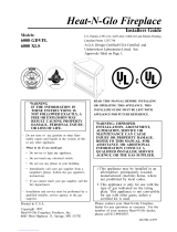
Heat-N-Glo Fireplace
Models:
SL-950TR
SL-750TR
SL-750TRS
SL-550TR
SL-550TRS
Installers Guide
530-982-B 10/98
- Do not store or use gasoline or other flam-
mable vapors and liquids in the vicinity of
this or any other appliance.
-What to do if you smell gas
• Do not try to light any appliance.
• Do not touch any electrical switch.
• Do not use any phone in your building.
• Immediately call your gas supplier from a
neighbor's phone. Follow the gas supplier's
instructions.
• If you cannot reach your gas supplier, call
the fire department.
- Installation and service must be performed by a
qualified installer, service agency, or the gas
supplier.
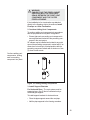
WARNING: IMPROPER INSTALLATION,
ADJUSTMENT, ALTERATION, SER-
VICE OR MAINTENANCE CAN CAUSE
INJURY OR PROPERTY DAMAGE.
REFER TO THIS MANUAL. FOR ASSIS-
TANCE OR ADDITIONAL INFORMA-
TION CONSULT A QUALIFIED IN-
STALLER, SERVICE AGENCY, OR THE
GAS SUPPLIER.
Underwriters
Laboratories Listed
READ THIS MANUAL BEFORE INSTALLING OR
OPERATING THIS APPLIANCE. THIS
INSTALLERS GUIDE
MUST BE LEFT WITH
APPLIANCE FOR FUTURE REFERENCE.
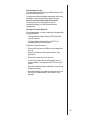
1. This appliance may be installed in an
aftermarket, permanently located,
manufactured (mobile) home, where
not prohibited by local codes.
2.This appliance is only for use with the
type of gas indicated on the rating
plate. This appliance is not convertible
for use with other gases, unless a
certified kit is used.
Please contact your Heat-N-Glo dealer for any
questions or concerns. For the number of your
nearest Heat-N-Glo dealer, please call 612-890-8367.
Printed in U.S.A. Copyright 1998,
Heat-N-Glo, a division Hearth Technologies Inc.
6665 West Highway 13, Savage, MN 55378
WARNING: IF THE
INFORMATION IN THESE
INSTRUCTIONS IS NOT
FOLLOWED EXACTLY, A FIRE
OR EXPLOSION MAY RESULT
CAUSING PROPERTY DAMAGE,
PERSONAL INJURY, OR DEATH.
This product is covered by one or more of the following patents: (United States) 4,112,913; 4,408,594; 4,422,426; 4,424,792; 4,520,791; 4,793,322;
4,852,548; 4,875,464; 5,000,162; 5,016,609; 5,076,254 5,191,877; 5,218,953; 5,328,356; 5,429,495; 5,452,708; 5,542,407; 5,613,487; (Australia)
543790; 586383; (Canada) 1,123,296; 1,297,746; 2,195,264; (Mexico) 97-0457; (New Zealand) 200265; or other U.S. and foreign patents pending.

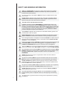
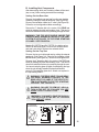
SAFETY AND WARNING INFORMATION
READ and UNDERSTAND all instructions carefully before starting the installation.
FAILURE TO FOLLOW these installation instructions may result in a possible fire
hazard and will void the warranty.
Prior to the first firing of the fireplace, READ the Using Your Fireplace section of the
Owners Guide.
DO NOT USE this appliance if any part has been under water. Immediately CALL a
qualified service technician to inspect the unit and to replace any part of the control
system and any gas control which has been underwater.
THIS UNIT IS NOT FOR USE WITH SOLID FUEL.
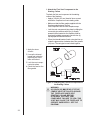
Installation and repair should be PERFORMED by a qualified service person. The
appliance and venting system should be INSPECTED before initial use and at least
annually by a professional service person. More frequent cleaning may be required due
to excessive lint from carpeting, bedding material, etc. It is IMPERATIVE that the units
control compartment, burners, and circulating air passageways BE KEPT CLEAN to
provide for adequate combustion and ventilation air.
Always KEEP the appliance clear and free from combustible materials, gasoline, and
other flammable vapors and liquids.
NEVER OBSTRUCT the flow of combustion and ventilation air. Keep the front of the
appliance CLEAR of all obstacles and materials for sevicing and proper operations.
Due to the high temperature, the appliance should be LOCATED out of traffic areas and
away from furniture and draperies. Clothing or flammable material SHOULD NOT BE
PLACED on or near the appliance.
Children and adults should be ALERTED to the hazards of high surface temperature and
should STAY AWAY to avoid burns or clothing ignition. Young children should be
CAREFULLY SUPERVISED when they are in the same room as the appliance.
These units MUST use one of the vent systems described in the Installing the Fireplace
section of the Installers Guide. NO OTHER vent systems or components MAY BE USED.
This gas fireplace and vent assembly MUST be vented directly to the outside and MUST
NEVER be attached to a chimney serving a separate solid fuel burning appliance. Each
gas appliance MUST USE a separate vent system. Common vent systems are
PROHIBITED.
INSPECT the external vent cap on a regular basis to make sure that no debris is
interfering with the air flow.
The glass door assembly MUST be in place and sealed, and the trim door assembly
MUST be in place on the fireplace before the unit can be placed into safe operation.
DO NOT OPERATE this appliance with the glass door removed, cracked, or broken.
Replacement of the glass door should be performed by a licensed or qualified service
person. DO NOT strike or slam the glass door.
The glass door assembly SHALL ONLY be replaced as a complete unit, as supplied by
the gas fireplace manufacturer. NO SUBSTITUTE material may be used.
DO NOT USE abrasive cleaners on the glass door assembly. DO NOT ATTEMPT to
clean the glass door when it is hot.
Turn off the gas before servicing this appliance. It is recommended that a qualified
service technician perform an appliance check-up at the beginning of each heating
season.
Any safety screen or guard removed for servicing must be replaced before operating
this appliance.
!
!
!
!
!
!
!
!
!
!
!
!
!
!
!
!
!
!
i

Table of
Contents
Safety and Warning Information ................... i
Section 1: Approvals and Codes .................1
Approval Listings and Codes ............................. 1
Appliance Certification .................................... 1
Installation Codes ........................................... 1
High Altitude Installations ................................ 2
Section 2: Getting Started............................. 3
Introducing the Heat-N-Glo Gas Fireplaces ........ 3
Pre-installation Preparation ................................ 3
Section 3: Installing the Fireplace ................8
Step 1 Locating the Fireplace .......................... 8
Step 2 Framing the Fireplace .......................... 9
Step 3 Installing the Vent System .................. 10
A. Vent System Approvals ........................... 10
B. Installing Vent Components ..................... 28
C. Vent Termination ...................................... 34
Step 4 Positioning, Leveling and
Securing the Fireplace ........................ 39
Step 5 The Gas Control Systems .................. 39
Step 6 The Gas Supply Line .......................... 40
Step 7 Gas Pressure Requirements ............. 41
Step 8 Wiring the Fireplace ........................... 42
Step 9 Finishing ............................................. 44
Step 10 Installing Trim, Logs and
Ember Material ................................... 45
Installing the Trim ......................................... 45
Positioning the Logs ..................................... 46
Placing the Ember Material .......................... 46
Step 11 Before Lighting the Fireplace ............. 48
Step 12 Lighting the Fireplace ........................ 48
After the Installation .......................................... 48
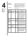
Section 4: Maintenance and Servicing ......49
Section 5: Replacement Parts
and Accessories ........................51
Replacement Parts .......................................... 51
Accessories ..................................................... 55
i i

1
1
Approvals
and Codes
Approval Listings
and Codes
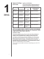
Appliance Certification
The Heat-N-Glo fireplace models discussed in this
Installers Guide have been tested to certification
standards and listed by the applicable laboratories.
CERTIFICATION
MODEL LABORATORY TYPE STANDARD
SL-950TR Underwriters Direct Vent ANSI Z21.50CGA2.22
Laboratories Decorative
SL-750TR Underwriters Direct Vent ANSI Z21.50 CGA2.22
Laboratories Decorative
SL-750TRS Underwriters Direct Vent ANSI Z21.88CSA2.33
Laboratories Gas Fireplace
Heater
SL-550TR Underwriters Direct Vent ANSI Z21.50CGA2.22
Laboratories Decorative
SL-550TRS Underwriters Direct Vent ANSI Z21.88CSA2.33
Laboratories Gas Fireplace
Heater
NOTE: ALL MODELS ARE UL LISTED TO UL307B, THE STANDARD
FOR GAS-BURNING HEATING APPLIANCES FOR MANUFACTURED
HOMES AND RECREATIONAL VEHICLES.
Installation Codes
The fireplace installation must conform to local codes. Before installing the
fireplace, consult the local building code agency to ensure that you are in
compliance with all applicable codes, including permits and inspections.
In the absence of local codes, the fireplace installation must conform to the
National Fuel Gas Code ANSI Z223.1 (in the United States) or the CAN/CGA-
B149 Installation Codes (in Canada). The appliance must be electrically
grounded in accordance with local codes or, in the absence of local codes with
the National Electric Code ANSI/NFPA No. 70 (in the United States), or to the
CSA C22.1 Canadian Electric Code (in Canada).
These models may be installed in a bedroom or bed-sitting room in the U.S.A.
and Canada.

2
High Altitude Installations
U.L. Listed gas fireplaces are tested and approved for elevations from 0 to
2,000 feet in the U. S. A. and from 0 to 4,500 feet in Canada.
When installing this fireplace at an elevation above 2,000 feet (in the United
States), it may be necessary to decrease the input rating by changing the
existing burner orifice to a smaller size. Input should be reduced four percent
(4%) for each 1,000 feet above sea level, unless the heating value of the gas
has been reduced, in which case this general rule will not apply. To identify the
proper orifice size, check with the local gas utility.
When installing this fireplace at an elevation between 2,000 and 4,500 feet (in
Canada), the input rating must be reduced by ten percent (10%).
When installing this fireplace at an elevation above 4,500 feet (in Canada),
check with local authorities.
Consult your local gas utility for assistance in determining the proper orifice for
your location.

3
2
Getting
Started
Introducing the
Heat-N-Glo
Gas Fireplaces
Heat-N-Glo direct vent gas fireplaces are designed to
operate with all combustion air siphoned from outside
of the building and all exhaust gases expelled to the
outside.
The information contained in this Installers Guide,
unless noted otherwise, applies to all models and gas
control systems.
Gas fireplace diagrams, including the dimensions, are
shown in this section.
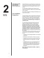
Pre-installation
Preparation
This gas fireplace and its components are tested and
safe when installed in accordance with this Installers
Guide. Report to your dealer any parts damaged in
shipment, particularly the condition of the glass. Do
not install any unit with damaged, incomplete, or
substitute parts.
The vent system components and trim doors are
shipped in separate packages. The gas logs are
packaged separately and must be field installed.
Read all of the instructions before starting the
installation. Follow these instructions carefully
during the installation to ensure maximum safety
and benefit. Failure to follow these instructions
will void the owners warranty and may present a
fire hazard.
The Heat-N-Glo Warranty will be voided by, and Heat-
N-Glo disclaims any responsibility for, the following
actions:
Installation of any damaged fireplace or vent system
component.
Modification of the fireplace or direct vent system.
Installation other than as instructed by Heat-N-Glo.
Improper positioning of the gas logs or the glass
door.
Installation and/or use of any component part not
manufactured and approved by Heat-N-Glo, not
withstanding any independent testing laboratory or
other party approval of such component part or
accessory.
ANY SUCH ACTION MAY POSSIBLY CAUSE A
FIRE HAZARD.

4
When planning a fireplace installation, its necessary to determine:
Where the unit is to be installed.
The vent system configuration to be used.
Gas supply piping.
Electrical wiring.
Framing and finishing details.
Whether optional accessoriesdevices such as a fan, wall switch, or remote
controlare desired.
If the fireplace is to be installed on carpeting or tile, or on any combustible
material other than wood flooring, the fireplace should be installed on a metal or
wood panel that extends the full width and depth of the fireplace.

5
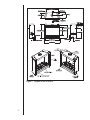
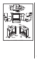
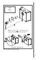
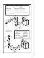
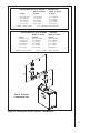
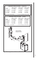
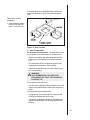
Figure 1. Diagram of the SL-950TR

6
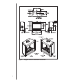
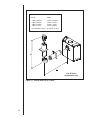
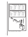
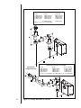
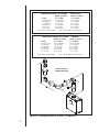
Figure 2. Diagram of the SL-750TR and SL-750TRS

7
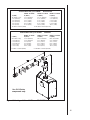
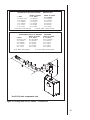
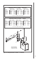
Figure 3. Diagram of the SL-550TR and SL-550TRS

8
3
Installing the
Fireplace
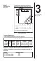
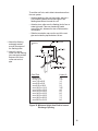
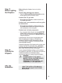
Step 1
Locating the
Fireplace
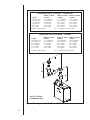
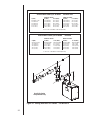
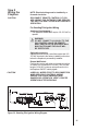
The diagram below shows space and clearance
requirements for locating a fireplace within a room.
ABCD E
SL-950TR 49 16 1/4 35 3/8 50 70 3/4
SL-750TR &
SL-750TRS 42 16 1/4 31 7/8 45 63 3/4
SL-550TR &
SL-550TRS 37 16 1/4 29 3/8 41 1/2 58 3/4
NOTE: DIMENSIONS SHOWN IN INCHES.
Figure 4. Fireplace Dimensions, Locations, and
Space Requirements
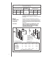
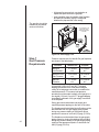
Clearance Requirements
The top and back of the fireplace are defined by stand-offs.
MODEL RECESSED DEPTH
SL-950-TR 16 1/4
SL-750TR & SL-750TRS 16 1/4
SL-550TR & SL-550TRS 16 1/4
The minimum clearance to a perpendicular wall extending past the face of the
fireplace is 3 inches (76.2mm).
The back of the fireplaces may be recessed into combustible construction, as
shown below.
Minimum Clearances from the Fireplace to
Combustible Materials
Glass Back of Sides of Top of
Front Floor Fireplace Fireplace Fireplace Ceiling
36 inches 0 1/2 inch 1/2 inch
(914 mm)
SL-750TRS & SL-950TRS:
3
1/4
” (83mm)
SL-550TRS: 1
1/2
” (38mm)
31 inches
(787mm)
(13mm) (13mm)

9
Minimum Clearances from the Vent Pipe to
Combustible Materials
For Vertical
For Horizontal Sections Sections At Wall Firestops
Top Bottom Sides Top Bottom Sides
3 inches 1 inch 1 inch 1 inch 2-1/2 inches 1/2 inch 1 inch
(75 mm) (25 mm) (25 mm) (25 mm) (63.7 mm) (13 mm) (25 mm)
For minimum clearances, see the direct vent
termination clearance diagrams on pages 36 and 38 in
this section.
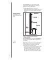
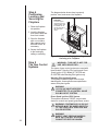
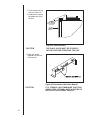
Step 2
Framing the
Fireplace
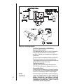
Fireplace framing can be built before or after the
fireplace is set in place. Framing should be positioned
to accommodate wall coverings and fireplace facing
material. The diagram below shows framing reference
dimensions.
CAUTION MEASURE FIREPLACE DIMENSIONS, AND
VERIFY FRAMING METHODS AND WALL
COVERING DETAILS, BEFORE FRAMING
CONSTRUCTION BEGINS.
Framing should be
constructed of 2 X 4 lumber or heavier.
The framing headers may rest
on the fireplace stand-offs.
Model A B C D E
SL-950TR 49 42 1/4 16 1/4 44 29 1/2
SL-750TR &
SL-750TRS 42 38 1/4 16 1/4 41 25 1/2
SL-550TR &
SL-550TRS 37 33 16 1/4 36 1/2 22
NOTE: DIMENSIONS SHOWN IN INCHES
Figure 5. Framing Dimensions
WARNING:
To ensure proper
clearances the front
framing header must be
installed on its narrow
edge and to the front of
the frame.

10
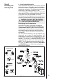
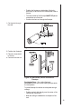
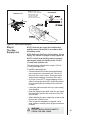
Vent System
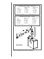
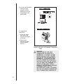
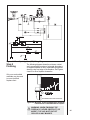
Termination Kits Vent System Components
SL D-SERIES
D-SERIES
DVK-01D DVK-TVCD
DVK-01TRD
SLK-01D
SLK-TVCD
SLK-01TRD
Figure 6. Vent Components and Terminations
A. Vent System Approvals
These models have vent starting collars on both the top and
the back of the unit. Depending upon the installation,
decide which ONE set of starting collars will be used to
attached the vent system. The starting collar sealing cap
must remain on the starting collar NOT used.
These models use SL-D-series, direct vent components
when using the TOP vent collars and D-series direct vent
components when using the REAR vent collars.
The flame and ember appearance may vary based on
the type of fuel burned and the venting configuration used.
WARNING YOU MUST NOT MIX D-SERIES
AND SL D-SERIES COMPONENTS IN ANY
VENT SYSTEM CONFIGURATION.
Identifying Vent Components
Approved vent system components are labeled for
identification. NO OTHER VENTING SYSTEMS OR
COMPONENTS MAY BE USED. Detailed installation
instructions are included with each vent termination kit
and should be used in conjunction with this Installers
Guide. Figure 6 shows vent system components and
terminations.
The vent systems installed on this gas fireplace may
include one, two, or three 90° elbow assemblies. The
relationships of vertical rise to horizontal run in vent
configurations using 90° elbows MUST BE strictly
adhered to. The rise to run relationships are shown in the
venting drawings and tables on the next several pages.
NOTE: Two 45° elbows may be used in place of one
90° elbow. You MUST always maintain the MAXIMUM
and MINIMUM rise-to-run ratios in the vent system
when using 45° elbows.
Step 3
Installing the
Vent System

11
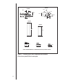
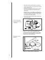
Figure 7. D-Series Direct Vent Component Specifications
(5-inch inner pipe/8 5/8-inch outer pipe)
NOTE: PIPES OVERLAP 1 3/8 INCHES (34.93 mm) AT EACH JOINT.
DV-90D
6 5/32
5 7/87 3/8
DV-45D
6 7/16
11 1/16 6 1/2
8 5/8
8 1/2
5 1/16
8 /12 11 5/8
8 5/8
11 15/16
DV-36D
35 3/4
47 3/4
DV-48D
5 3/4
8 3/4
11 3/4
DV-12D DV-09D DV-06D
6-5/32"
7-3/8" 5-7/8"
8-1/2"
8-5/8"
(220 mm)
11-15/16"
11-5/8" 11-1/16"
6-1/2"
8-5/8"
5-1/16"
8-1/2"
6-7/16"
35-3/4"
47-3/4"
11-3/4" 8-3/4" 5-3/4"
NOTE: PIPES OVERLAP 1-3/8 INCHES (34.93 mm) AT EACH JOINT.

12
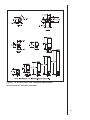
Figure 8. SL D-Series Direct Vent Component Specifications
(4-inch inner pipe / 6 5/8-inch outer pipe)

13
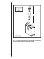
STRAIGHT UP
VERTICAL VENTING
V (FT.)
40' MAX.
Figure 9. Straight up Vertical Venting
NOTE: For vertical venting over 20 feet a restrictor plate is recommended
for improved flame appearance. See accessories page.
Use SL D-Series
components only.

14
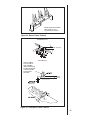
STRAIGHT OUT HORIZONTAL
VENTING
H
Max. Run
24" (610 mm)
Use D-Series components only.
Figure 10. Straight Out Horizontal Venting
Note: You may use a 45o elbow in corner installations for models
SL-550TR and SL-750TR ONLY. Use two 90o elbows for corner
installations on SL-550TRS, SL-750TRS and SL-950TR.

15
VENTING WITH ONE (1) 90o ELBOW
V (FT.) H (FT.)
1' MIN. (305mm) 2' MAX. (610mm)
2' MIN. (610mm) 4' MAX. (1.22m)
3' MIN. (914mm) 6' MAX. (1.86m)
4' MIN. (1.22m) 8' MAX. (2.48m)
V+H =40' MAX. (12.2m) H= 8' MAX. (2.48m)
Use D-Series
components only.
Figure 11. Venting with One 90° Elbow

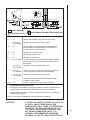
16
Figure 12. Venting with One 90° Elbow - TR MODELS
MODEL SL-550TR
V (MIN.) H (MAX.)
90o Elbow on Top 2.5 FT (863mm)
1 FT (305mm) 3 FT (914mm)
2 FT (610mm) 4 FT (1.22m)
3 FT (914mm) 6 FT (1.86m)
4 FT (1.22m) 8 FT (2.48m)
5 FT (1.52m) 16 FT (4.8m)
Use SL D-Series
components only.
VENTING WITH ONE (1) 90o ELBOW NATURAL GAS
H MAX. = 16 FT (4.8m) V + H MAX. = 40 FT (12.2m)
MODEL SL-750TR MODEL SL-950TR
H (MAX.) H (MAX.)
2.5 FT (863mm) 2 FT (610mm)
3 FT (914mm) 3 FT (914mm)
4 FT (1.22m) 4 FT (1.22m)
6 FT (1.86m) 6 FT (1.86m)
8 FT (2.48m) 8 FT (2.48m)
16 FT (4.8m) 16 FT (4.8m)
MODEL SL-550TR
V (MIN.) H (MAX.)
90o Elbow on Top 2.5 FT (863mm)
1 FT (305mm) 2.5 FT (863mm)
2 FT (610mm) 4 FT (1.22m)
3 FT (914mm) 6 FT (1.86m)
4 FT (1.22m) 8 FT (2.48m)
5 FT (1.52m) 16 FT (4.8m)
VENTING WITH ONE (1) 90o ELBOW PROPANE
H MAX. = 16 FT (4.8m) V + H MAX. = 40 FT (12.2m)
MODEL SL-750TR MODEL SL-950TR
H (MAX.) H (MAX.)
NOT ALLOWED NOT ALLOWED
2 FT (610mm) 2 FT (610mm)
4 FT (1.22m) 4 FT (1.22m)
6 FT (1.86m) 6 FT (1.86m)
8 FT (2.48m) 8 FT (2.48m)
16 FT (4.8m) 16 FT (4.8m)

17
Figure 13. Venting with One 90° Elbow - TRS MODELS
MODEL SL-550TRS
V (MIN.) H (MAX.)
90o Elbow on Top 2 FT (610mm)
1 FT (305mm) 3 FT (914mm)
2 FT (610mm) 4 FT (1.22m)
3 FT (914mm) 6 FT (1.86m)
4 FT (1.22m) 8 FT (2.48m)
5 FT (1.52m) 16 FT (4.8m)
Use SL D-Series
components only.
VENTING WITH ONE (1) 90o ELBOW NATURAL GAS
H MAX. = 16 FT (4.8m) V + H MAX. = 40 FT (12.2m)
MODEL SL-750TRS
H (MAX.)
2 FT (610mm)
3 FT (914mm)
4 FT (1.22m)
6 FT (1.86m)
8 FT (2.48m)
16 FT (4.8m)
VENTING WITH ONE (1) 90o ELBOW PROPANE
MODEL SL-550TRS
V (MIN.) H (MAX.)
90o Elbow on Top NOT ALLOWED
1 FT (305mm) 2 FT (610mm)
2 FT (610mm) 4 FT (1.22m)
3 FT (914mm) 6 FT (1.86m)
4 FT (1.22m) 8 FT (2.48m)
5 FT (1.52m) 16 FT (4.8m)
H MAX. = 16 FT (4.8m) V + H MAX. = 40 FT (12.2m)
MODEL SL-750TRS
H (MAX.)
NOT ALLOWED
2 FT (610mm)
4 FT (1.22m)
6 FT (1.86m)
8 FT (2.48m)
16 FT (4.8m)
Page is loading ...
Page is loading ...
Page is loading ...
Page is loading ...
Page is loading ...
Page is loading ...
Page is loading ...
Page is loading ...
Page is loading ...
Page is loading ...
Page is loading ...
Page is loading ...
Page is loading ...
Page is loading ...
Page is loading ...
Page is loading ...
Page is loading ...
Page is loading ...
Page is loading ...
Page is loading ...
Page is loading ...
Page is loading ...
Page is loading ...
Page is loading ...
Page is loading ...
Page is loading ...
Page is loading ...
Page is loading ...
Page is loading ...
Page is loading ...
Page is loading ...
Page is loading ...
Page is loading ...
-
 1
1
-
 2
2
-
 3
3
-
 4
4
-
 5
5
-
 6
6
-
 7
7
-
 8
8
-
 9
9
-
 10
10
-
 11
11
-
 12
12
-
 13
13
-
 14
14
-
 15
15
-
 16
16
-
 17
17
-
 18
18
-
 19
19
-
 20
20
-
 21
21
-
 22
22
-
 23
23
-
 24
24
-
 25
25
-
 26
26
-
 27
27
-
 28
28
-
 29
29
-
 30
30
-
 31
31
-
 32
32
-
 33
33
-
 34
34
-
 35
35
-
 36
36
-
 37
37
-
 38
38
-
 39
39
-
 40
40
-
 41
41
-
 42
42
-
 43
43
-
 44
44
-
 45
45
-
 46
46
-
 47
47
-
 48
48
-
 49
49
-
 50
50
-
 51
51
-
 52
52
-
 53
53


Heat & Glo SL-550TR/750TR & TRS & SL-950TR Install Manual
- Category
- Fireplaces
- Type
- Install Manual
Ask a question and I''ll find the answer in the document
Finding information in a document is now easier with AI
Related papers
-
Heat & Glo BE-36 Install Manual
-
-
-
-
-
-
-
-
-
Other documents
-
 Heat-N-Glo 6000 XLS Installer's Manual
-
 Heat-N-Glo 7000TV Installer's Manual
-
 Heat-N-Glo R-CORNER-TRC Installer's Manual
-
Hearth and Home Technologies BE-36-CIPI User manual
-
Quadra-Fire QV32B-A User manual
-
 Quadrafire QV32 / QV36 Install Manual
-
-
Heat & Glo LifeStyle 8000TRD User manual
-
-


