Page is loading ...

1
-Do not store or use gasoline or other flam-
mable vapors and liquids in the vicinity of this
or any other appliance.
-What to do if you smell gas
•Do not try to light any appliance.
•Do not touch any electrical switch.
•Do not use any phone in your building.
•Immediately call your gas supplier from a
neighbor's phone. Follow the gas supplier's
instructions.
•If you cannot reach your gas supplier, call
the fire department.
-Installation and service must be performed by a
qualified installer, service agency, or the gas
supplier.
Models:
SL-750TRS-C
SL-550TRS-C
SL-350TRS-C
Installers Guide
WARNING: IMPROPER INSTALLA-
TION, ADJUSTMENT, ALTERATION,
SERVICE OR MAINTENANCE CAN
CAUSE INJURY OR PROPERTY DAM-
AGE. REFER TO THIS MANUAL. FOR
ASSISTANCE OR ADDITIONAL INFOR-
MATION CONSULT A QUALIFIED IN-
STALLER, SERVICE AGENCY, OR THE
GAS SUPPLIER.
Underwriters
Laboratories Listed
534-985I 8/03
READ THIS MANUAL BEFORE INSTALLING OR
OPERATING THIS APPLIANCE. THIS INSTALLERS
GUIDE MUST BE LEFT WITH APPLIANCE FOR
FUTURE REFERENCE.
1.This appliance may be installed in an af-
termarket, permanently located, manufac-
tured (mobile) home, where not prohibited
by local codes.
2.This appliance is only for use with the type
of gas indicated on the rating plate. This
appliance is not convertible for use with
other gases, unless a certified kit is used.
Please contact your Heat-N-Glo dealer with any
questions or concerns. For the number of your nearest
Heat-N-Glo dealer, please call 1-888-427-3973.
Printed in U.S.A. Copyright 2003,
Heat-N-Glo, a brand of Hearth & Home Technologies Inc.
20802 Kensington Boulevard, Lakeville, MN 55044
WARNING: IF THE INFORMATION
IN THESE INSTRUCTIONS IS NOT
FOLLOWED EXACTLY, A FIRE OR
EXPLOSION MAY RESULT CAUS-
ING PROPERTY DAMAGE, PER-
SONAL INJURY, OR DEATH.
This product is covered by one or more of the following patents: (United States) 4,112,913; 4,408,594; 4,422,426; 4,424,792; 4,520,791; 4,793,322;
4,852,548; 4,875,464; 5,000,162; 5,016,609; 5,076,254 5,191,877; 5,218,953; 5,328,356; 5,429,495; 5,452,708; 5,542,407; 5,613,487; (Australia)
543790; 586383; (Canada) 1,123,296; 1,297,746; 2,195,264; (Mexico) 97-0457; (New Zealand) 200265; or other U.S. and foreign patents pending.

2
These units MUST use one of the vent systems
described in the Installing the Fireplace section of
the Installers Guide. NO OTHER vent systems or
components MAY BE USED.
This gas fireplace and vent assembly MUST be
vented directly to the outside and MUST NEVER be
attached to a chimney serving a separate solid fuel
burning appliance. Each gas appliance MUST USE
a separate vent system. Common vent systems are
PROHIBITED.
INSPECT the external vent cap on a regular basis to
make sure that no debris is interfering with the air
flow.
The glass door assembly MUST be in place and
sealed, and the trim door assembly MUST be in
place on the fireplace before the unit can be placed
into safe operation.
DO NOT OPERATE this appliance with the glass
door removed, cracked, or broken. Replacement of
the glass door should be performed by a licensed
or qualified service person. DO NOT strike or slam
the glass door.
The glass door assembly SHALL ONLY be
replaced as a complete unit, as supplied by the gas
fireplace manufacturer. NO SUBSTITUTE material
may be used.
DO NOT USE abrasive cleaners on the glass door
assembly. DO NOT ATTEMPT to clean the glass
door when it is hot.
Turn off the gas before servicing this appliance. It is
recommended that a qualified service technician
perform an appliance check-up at the beginning of
each heating season.
Any safety screen or guard removed for servicing
must be replaced before operating this appliance.
DO NOT place furniture or any other combustible
household objects within 36 inches of the fireplace
front.
READ and UNDERSTAND all instructions carefully
before starting the installation. FAILURE TO
FOLLOW these installation instructions may result
in a possible fire hazard and will void the warranty.
Prior to the first firing of the fireplace, READ the
Using Your Fireplace section of the Owners Guide.
DO NOT USE this appliance if any part has been
under water. Immediately CALL a qualified service
technician to inspect the unit and to replace any part
of the control system and any gas control which has
been under water.
THIS UNIT IS NOT FOR USE WITH SOLID FUEL.
Installation and repair should be PERFORMED by a
qualified service person. The appliance and venting
system should be INSPECTED before initial use
and at least annually by a professional service
person. More frequent cleaning may be required
due to excessive lint from carpeting, bedding
material, etc. It is IMPERATIVE that the unit’s
control compartment, burners, and circulating air
passageways BE KEPT CLEAN to provide for
adequate combustion and ventilation air.
Always KEEP the appliance clear and free from
combustible materials, gasoline, and other
flammable vapors and liquids.
NEVER OBSTRUCT the flow of combustion and
ventilation air. Keep the front of the appliance
CLEAR of all obstacles and materials for servicing
and proper operations.
Due to the high temperature, the appliance should
be LOCATED out of traffic areas and away from
furniture and draperies. Clothing or flammable
material SHOULD NOT BE PLACED on or near the
appliance.
Children and adults should be ALERTED to the
hazards of high surface temperature and should
STAY AWAY to avoid burns or clothing ignition.
Young children should be CAREFULLY SUPERVISED
when they are in the same room as the appliance.
!
!
!
!
!!
!
!!
!
!
!
!
!
!
!
!
SAFETY AND WARNING INFORMATION
!
!

3
TABLE OF CONTENTS
Safety and Warning Information ......................................................2
Service Parts Lists............................................................................4
Section 1: Approvals and Codes ....................................................10
Appliance Certification.......................................................................10
Installation Codes .............................................................................10
High Altitude Installations ..................................................................10
Section 2: Getting Started.............................................................. 11
Introducing the Heat-N-Glo Gas Fireplaces ......................................... 11
Pre-installation Preparation................................................................ 11
Section 3: Installing the Fireplace .................................................15
Constructing the Fireplace Chase ......................................................15
Step 1 Locating the Fireplace .......................................................15
Step 2 Framing the Fireplace........................................................16
Step 3 Installing the Vent System .................................................19
A. Vent System Approvals ................................................19
B. Installing Vent Components ..........................................29
C. Vent Termination ..........................................................32
Step 4 Positioning, Leveling, and
Securing the Fireplace.......................................................35
Step 5 The Gas Control Systems..................................................35
Step 6 The Gas Supply Line .........................................................36
Step 7 Gas Pressure Requirements ..............................................36
Step 8 Wiring the Fireplace ..........................................................37
Step 9 Finishing .......................................................................... 38
Step 10 Installing Trim, Logs, and Ember Material ........................... 39
Installing the Trim .............................................................. 39
Removing Grate Shipping Support ........................................ 39
Positioning the Logs .......................................................... 39
Shutter Settings ................................................................ 39
Placing the Ember Material ................................................ 39
Glass Specifications .......................................................... 39
Step 11 Before Lighting the Fireplace .............................................. 40
Step 12 Lighting the Fireplace ........................................................ 40
After the Installation .......................................................................... 40
Section 4: Maintaining and Servicing Your Fireplace ................... 41
u = Contains updated information.
u

4
(NG, LP) Exploded Parts Diagram
(GN, PL) Vue éclatée des pièces
Service Parts SL-350TRS-C
Beginning Manufacturing Date: 2-01
Ending Manufacturing Date: ______
* Part number list on following page.
* La liste des numéros de pièce se trouve
à la page suivante.
13
6
2
3
4
5
1
17
7 Log Set Assembly
12 8
11 10 9
14
15
23
22
20
21
19
18
16
24

5
(NG, LP) Service Parts List / Liste des pièces de rechange
IMPORTANT: THIS IS DATED INFORMATION. The most current information is located on your dealers VIP site. When order-
ing, supply serial and model numbers to ensure correct service parts. / IMPORTANT : L'information fournie dans cette brochure
n'est valide que pendant une courte période. Les sites VIP des distributeurs disposent des renseignements les plus récents.
Lors d'une commande, veuillez fournir les numéros de série et de modèles pour un remplacement adéquat des pièces.
SL-350TRS-C
ITEM /
PIÈCE STANDING PILOT SERIAL # / N° DE SÉRIE PART NUMBER
/ N° DE PIÈCE
Burner Orifice NG (#43C) / Orifice de brûleur GN (#43C) 582-843
Burner Orifice LP (#55C) / Orifice de brûleur PL (#55C) 582-855
1Valve NG / Valve GN 060-522
1Valve LP / Valve PL 060-523
2Burner NG, LP / Brûleur GN, PL 540-234A
3Glass Door Assembly / Porte en verre GLA-350TRS
4Log Grate / Grille de Bûche 540-361A
5Base Refractory / Réfractaire Base 540-206T
6Hood / Hotte SRV540-174
7Log Set Assembly / Jeu de Bûches LOGS-350
8Log 1 / Bûche 1 SRV530-701
9Log 2 / Bûche 2 SRV530-704
10 Log 3 / Bûche 3 SRV540-702
11 Log 4 / Bûche 4 SRV530-705
12 Log 5 / Bûche 5 SRV530-703
13 Junction Box / Boîtier de raccordement 100-250A
14 Louver, Top / Louvre, supérieure 540-256A
15 Louver, Bottom / Louvre, inférieure 540-257A
16 Wire Assembly / Module de fil 049-552A
17 Pilot Bracket / Parenthèse Pilote 530-164
18 Valve Bracket / Parenthèse de Valve 550-169
19 Flex Ball Valve Assembly / Fléchir l'Assemblée de Soupape de Balle 302-320A
20 Burner Tube / Tube de brûleur PRE 22099930
POST 22099930 567-301A
530-302A
21 Piezo Ignitor / Allumage Piézo 418-513
22 ON/OFF Rocker Switch / Interrupteur à bascule marche/arrêt 060-511
23 Pilot Assembly NG / Module de veilleuse GN 485-510A
23 Pilot Assembly LP / Module de veilleuse PL 485-511A
24 Mesh Panel Door / Engrener la Porte de Panneau 540-382A
Pilot Orifice NG / Orifice de veilleuse GN 446-505
Pilot Orifice LP / Orifice de veilleuse PL 446-517
Thermocouple / Thermocouple 446-511
Thermopile / Thermopile 060-512
Conversion Kit NG / Module de conversion GN NGK-350TRS-C
Conversion Kit LP / Module de conversion PL LPK-350TRS-C
Vermiculite Embers MYSTIC-EMBERS

6
(NG, LP) Exploded Parts Diagram
(GN, PL) Vue éclatée des pièces
Service Parts SL-550TRS-C
Beginning Manufacturing Date: 2-01
Ending Manufacturing Date: ______
9
7 Log Set Assembly
8
13 12
11 10
* Part number list on following page.
* La liste des numéros de pièce se trouve
à la page suivante.
14
16
6
2
3
15
4
5
25
1
22
23
21
20
19 18
17
24

7
(NG, LP) Service Parts List / Liste des pièces de rechange
IMPORTANT: THIS IS DATED INFORMATION. The most current information is located on your dealers VIP site. When ordering,
supply serial and model numbers to ensure correct service parts. / IMPORTANT : L'information fournie dans cette brochure n'est
valide que pendant une courte période. Les sites VIP des distributeurs disposent des renseignements les plus récents. Lors
d'une commande, veuillez fournir les numéros de série et de modèles pour un remplacement adéquat des pièces.
SL-550TRS-C
ITEM /
PIÈCE STANDING PILOT IGNITION / D’ALLUMAGE PAR VEILLEUSE SERIAL # / N° DE SÉRIE PART NUMBER
/ N° DE PIÈCE
Burner Orifice NG (#38C) / Orifice de brûleur GN (#38C) 582-838
Burner Orifice LP (#52C) / Orifice de brûleur PL (#52C) 582-852
1Burner Tube / Tube de brûleur PRE 22099930
POST 22099930 567-301A
530-302A
2Burner NG / Brûleur GN 547-208A
2Burner LP / Brûleur PL 547-210A
3Glass Door Assembly / Porte en verre GLA-550TRS
4Log Grate / Grille de Bûche 550-361A
5Base Refractory NG, LP / Réfractaire Base NG, PL 550-117T
6Hood / Hotte SRV550-175
7Log Set Assembly / Module de Jeu de Bûches LOGS-SL550
8Log 1 / Bûche 1 SRV550-715
9Log 2 / Bûche 2 SRV550-714
10 Log 3 / Bûche 3 SRV550-717
11 Log 4 / Bûche 4 SRV550-716
12 Log 5 / Bûche 5 SRV550-718
13 Log 6 / Bûche 6 SRV438-724
14 Junction Box / Boîtier de raccordement 100-250A
15 Louver, Top / Louvre, supérieure 550-251A
16 Louver, Bottom / Louvre, inférieure 550-248A
17 Door Assembly / Assemblée de Porte 550-140A
18 Valve NG / Valve GN 060-522
18 Valve LP / Valve PL 060-523
19 ON/OFF Rocker Switch / Interrupteur à bascule MARCHE/ARRÊT 060-511
20 Piezo Ignitor / Allumage Piézo 418-513
21 Wire Assembly / Module de fil 049-552A
22 Flex Ball Valve Assembly / Fléchir l'Assemblée de Soupape de Balle 302-320A
23 Valve Bracket / Parenthèse de Valve 550-169
24 Pilot Assembly NG / Module de veilleuse GN 485-510A
24 Pilot Assembly LP / Module de veilleuse PL 485-511A
25 Pilot Bracket / Parenthèse Pilote 530-164
Pilot Orifice NG / Orifice de veilleuse GN 446-505
Pilot Orifice LP / Orifice de veilleuse PL 446-517
Thermocouple / Thermocouple 446-511
Thermopile / Thermopile 060-512
ACCESSORIES / ACCESSOIRES
Fan Kit / Module de ventilateur GFK-160A
Extended Vertical Baffle Kit / Module de verticale étendu le déflecteur BAF-VERT
Wall Switch Kit, Off-white / Module d'interrupteur mural, Blanc Cassé WSK-21
Wall Switch Kit, White / Module d'interrupteur mural, Blanc WSK-21-W
Conversion Kit NG / Module de conversion GN NGK-550TRS-C
Conversion Kit LP / Module de conversion PL LPK-550TRS-C
Vermiculite Embers MYSTIC-EMBERS

8
(NG, LP) Exploded Parts Diagram
(GN, PL) Vue éclatée des pièces
Service Parts SL-750TRS-C
Beginning Manufacturing Date: 2-01
Ending Manufacturing Date: ______
* Part number list on following page.
* La liste des numéros de pièce se trouve à la
page suivante.
9
7 Log Set Assembly
812 11
10
4
3
5
2
14
13
15
16
6
24
23
22
21
20
19
18 17
25
1

9
(NG, LP) Service Parts List / Liste des pièces de rechange
IMPORTANT: THIS IS DATED INFORMATION. The most current information is located on your dealers VIP site. When order-
ing, supply serial and model numbers to ensure correct service parts. / IMPORTANT : L'information fournie dans cette brochure
n'est valide que pendant une courte période. Les sites VIP des distributeurs disposent des renseignements les plus récents.
Lors d'une commande, veuillez fournir les numéros de série et de modèles pour un remplacement adéquat des pièces.
SL-750TRS-C
ITEM /
PIÈCE STANDING PILOT IGNITION / ALLUMAGE UNE VEILLEUSE SERIAL # / N° DE SÉRIE PART NUMBER
/ N° DE PIÈCE
Burner Orifice NG (#36C) / Orifice de brûleur GN (#36C) 582-836
Burner Orifice LP (#52C) / Orifice de brûleur PL (#52C) 582-852
1Burner Tube / Tube de brûleur PRE 22099930
POST 22099930 567-301A
530-302A
2Burner NG / Brûleur GN 534-211A
2Burner LP / Brûleur PL 534-215A
3Glass Door Assembly / Porte en verre GLA-750TRS
4Log Grate / Grille de Bûche 530-361A
5Base Refractory NG, LP / Réfractaire Base GN, PL 530-117T
6Hood / Hotte SRV530-175
7Log Set Assembly / Module de Jeu de Bûches LOGS-SL750
8Log 1 / Bûche 1 SRV530-714
9Log 2 / Bûche 2 SRV530-719
10 Log 3 / Bûche 3 SRV530-718
11 Log 4 / Bûche 4 SRV530-716
12 Log 5 / Bûche 5 SRV530-717
13 Log 6 / Bûche 6 SRV530-715
14 Junction Box / Boîtier de raccordement 100-250A
15 Bottom Louver Assembly / 530-258A
16 Top Louver Assembly / 530-256A
17 Valve NG / Valve GN 060-522
17 Valve LP / Valve PL 060-523
18 ON/OFF Rocker Switch / Interrupteur à bascule MARCHE/ARRÊT 060-511
19 Piezo Ignitor / Allumage Piézo 418-513
20 Wire Assembly / Module de fil 049-552A
21 Flex Ball Valve Assembly / Fléchir l'Assemblée de Soupape de Balle 302-320A
22 Valve Bracket / Parenthèse de Valve 550-169
23 Pilot Assembly NG / Module de veilleuse GN 485-510A
23 Pilot Assembly LP / Module de veilleuse PL 485-511A
24 Pilot Bracket / Parenthèse Pilote 530-164
25 Mesh Panel Door / Engrener la Porte de Panneau 530-140A
ACCESSORIES / ACCESSOIRES
Fan Kit / Module de ventilateur GFK-160A
Extended Vertical Baffle Kit / Module de verticale étendu le déflecteur BAF-VERT
Wall Switch Kit, Off-white / Module d'interrupteur mural, Blanc Cassé WSK-21
Wall Switch Kit, White / Module d'interrupteur mural, Blanc WSK-21-W
Conversion Kit NG / Module de conversion GN NGK-750TRS-C
Conversion Kit LP / Module de conversion PL LPK-750TRS-C
Vermiculite Embers MYSTIC-EMBERS

10
1
Approvals and
Codes
NOTE: THESE MODELS ARE UL LISTED TO UL307B,
THE STANDARD FOR GAS-BURNING HEATING APPLI-
ANCES FOR MANUFACTURED HOMES AND RECRE-
ATIONAL VEHICLES.
Installation Codes
The fireplace installation must conform to local codes. Before
installing the fireplace, consult the local building code
agency to ensure that you are in compliance with all
applicable codes, including permits and inspections.
In the absence of local codes, the fireplace installation must
conform to the National Fuel Gas Code ANSI Z223.1 (in
the United States) or the CAN/CGA-B149 Installation Codes
(in Canada). The appliance must be electrically grounded
in accordance with local codes or, in the absence of local
codes with the National Electric Code ANSI/NFPA No. 70
(in the United States), or to the CSA C22.1 Canadian Electric
Code (in Canada).
These models may be installed in a bedroom or bed-sitting
room in the U.S.A. and Canada.
Heat-N-Glo Quality
Systems registered
by SGS ICS
Appliance Certification
The Heat-N-Glo fireplace models discussed in this Installers
Guide have been tested to certification standards and listed
by the applicable laboratories.
Certification
MODELS: SL-750TRS-C, SL-550TRS-C, SL-350TRS-C
LABORATORY: Underwriters Laboratories
TYPE: Direct Vent Gas Fireplace Heater
STANDARD: ANSI Z21.88•CSA2.33•UL307B
High Altitude Installations
U.L. Listed gas appliances are tested and approved without
requiring changes for elevations from 0 to 2,000 feet in the
U. S. A. and in Canada.
When installing this appliance at an elevation above 2,000
feet, it may be necessary to decrease the input rating by
changing the existing burner orifice to a smaller size. Input
rate should be reduced by 4% for each 1000 feet above a
2000 foot elevation in the U.S.A. or 10% for elevations
between 2000 and 4500 feet in Canada. If the heating value
of the gas has been reduced, these rules do not apply. To
identify the proper orifice size, check with the local gas
utility.
If installing this appliance at an elevation above 4,500 feet
(in Canada), check with local authorities.

11
2
Getting Started
Introducing the Heat-N-Glo Gas Fireplaces
Heat-N-Glo direct vent gas fireplaces are designed to oper-
ate with all combustion air siphoned from outside of the
building and all exhaust gases expelled to the outside.
The information contained in this Installers Guide, unless
noted otherwise, applies to all models and gas control
systems. Gas fireplace diagrams, including the dimensions,
are shown in this section.
Pre-install Preparation
This gas fireplace and its components are tested and safe
when installed in accordance with this Installers Guide.
Report to your dealer any parts damaged in shipment,
particularly the condition of the glass. Do not install any
unit with damaged, incomplete, or substitute parts.
The vent system components and trim doors are shipped
in separate packages. The gas logs are packaged
separately and must be field installed.
Read all of the instructions before starting the
installation. Follow these instructions carefully during
the installation to ensure maximum safety and benefit.
Failure to follow these instructions will void the
owner’s warranty and may present a fire hazard.
The Heat-N-Glo Warranty will be voided by, and Heat-N-Glo
disclaims any responsibility for, the following actions:
•Installation of any damaged fireplace or vent system
component.
•Modification of the fireplace or direct vent system.
•Installation other than as instructed by Heat-N-Glo.
•Improper positioning of the gas logs or the glass door.
•Installation and/or use of any component part not manu-
factured and approved by Heat-N-Glo, not withstanding
any independent testing laboratory or other party approval
of such component part or accessory.
ANY SUCH ACTION MAY POSSIBLY CAUSE A FIRE
HAZARD.
When planning a fireplace installation, it’s necessary to
determine:
•Where the unit is to be installed.
•The vent system configuration to be used.
•Gas supply piping.
•Electrical wiring.
•Framing and finishing details.
•Whether optional accessories—devices such as a fan,
wall switch, or remote control—are desired.
If the fireplace is to be installed on carpeting or tile, or on
any combustible material other than wood flooring, the
fireplace should be installed on a metal or wood panel that
extends the full width and depth of the fireplace.

12
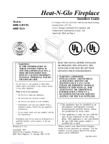
Figure 1. Diagram of the SL-750TRS-C
HOOD
GAS
CONTROLS
GAS LINE
ACCESS
VENT COLLARS
TOP STANDOFFS
ELECTRICAL
ACCESS
RATING PLATES
& LABELS
BOTTOM GRILLE
COVER
CERAMIC
FIBER PAD
30-11/16
(779mm) 1/2
(13mm)
15-5/16
(389mm)
16-3/8
(414mm)
8-3/4
(223mm)
Ø 6-5/8
(168mm)
15-7/8
(402mm)
37-3/4
(960mm)
ELECTRICAL
ACCESS
3-9/16
(90mm)
6-7/8
(174mm)
40-15/16
(1040mm)
36-1/8
(917mm)
35-5/8
(905mm)
25
(635mm)
40
(1016mm)
GAS LINE
ACCESS
2-1/8
(55mm)
5-1/16
(129mm)

13
Figure 2. Diagram of the SL-550TRS-C
Ø6-5/8
(168mm)
25-11/16
(653mm)
12-7/8
(326mm)
1/2
(13mm)
16-3/8
(414mm)
8-13/16
(223mm)
15-7/8
(402mm)
3-1/3
(90mm)
32-9/16
(828mm)
Ø8
(203mm)
21-7/16
(545mm)
6-7/8
(174mm)
ELECTRICAL
ACCESS
32-1/8
(815mm)
31-1/8
(790mm)
36
(913mm)
2-1/8
(55mm)
35-7/16
(901mm)
GAS LINE
ACCESS 5-1/16
(129mm)
HOOD
GAS
CONTROLS
GAS LINE
ACCESS
VENT COLLARS
TOP STANDOFFS
ELECTRICAL
ACCESS
RATING PLATES
& LABELS
BOTTOM GRILLE
COVER
CERAMIC
FIBER PAD

14
Figure 3. Diagram of the SL-350TRS-C
22-3/4
(576mm)
1/2
(13mm)
16-1/4
(413mm)
8-13/16
(223mm)
Ø 6-5/8
(168mm)
11-15/16
(288mm)
15-3/4
(400mm)
15-1/4
(388mm)
28-1/8
(714mm)
33
(837mm)
30-1/8
(764mm)
30-5/8
(777mm)
Ø 8
(203mm)
ELECTRICAL
ACCESS
3-1/2
(90mm)
6-7/8
(174mm0
34-7/16
(875mm)
2-1/8
(55mm)
GAS LINE
ACCESS 5-1/16
(129mm)
HOOD
GAS
CONTROLS
GAS LINE
ACCESS
VENT COLLARS
TOP STANDOFFS
ELECTRICAL
ACCESS
RATING PLATES
& LABELS
BOTTOM GRILLE
COVER
CERAMIC
FIBER PAD

15
3Installing the Fireplace
Step 1. Locating the Fireplace
Space and clearance requirements for locating a fireplace
within a room (see Figure 4).
Minimum Clearances
from the Fireplace to Combustible Materials
For minimum clearances, see the direct vent termination
clearance diagrams in Figures 29 and 30 in this manual.
Minimum Clearances
from the Vent Pipe to Combustible Materials
Inches mm
Vertical Sections. ............ 1............... 25
Horizontal Sections
Top .................................. 3............... 75
Bottom............................. 1............... 25
Sides ............................... 1............... 25
At Wall Firestops
Top ................................2 1/2............63.7
Bottom............................ 1/2.............. 13
Sides ............................... 1............... 25
*The clearance to the ceiling is measured from the top
of the unit, excluding the standoffs (see Figure 37).
The distance from the unit to combustible construction is to
be measured from the unit outer wrap surface to the com-
bustible construction, NOT from the screw heads that se-
cure the unit together.
1/2 “ MIN. (13mm)
C
3” MIN. (76mm)
A
B
D
E
Clearance Requirements
The top and back of the fireplace are defined by stand-offs.
The minimum clearance to a perpendicular wall extending
past the face of the fireplace is 3 inches (76mm). The back
of the fireplace may be recessed 16 1/4 inches (413mm)
into combustible construction.
Figure 4. Fireplace Dimensions, Locations,
and Space Requirements
Constructing the Fireplace Chase
A chase is a vertical box-like structure built to enclose the
gas fireplace and/or its vent system. Vertical vents that run
on the outside of a building may be, but are not required to
be, installed inside a chase.
CAUTION: TREATMENT OF FIRESTOP SPACERS AND
CONSTRUCTION OF THE CHASE MAY VARY WITH THE
TYPE OF BUILDING. THESE INSTRUCTIONS ARE NOT
SUBSTITUTES FOR THE REQUIREMENTS OF LOCAL
BUILDING CODES. THEREFORE, YOUR LOCAL BUILD-
ING CODES MUST BE CHECKED TO DETERMINE THE
REQUIREMENTS FOR THESE STEPS.
Factory-built fireplace chases should be constructed in the
manner of all outside walls of the home to prevent cold air
drafting problems. The chase should not break the outside
building envelope in any manner.
This means that the walls, ceiling, base plate and cantilever
floor of the chase should be insulated. Vapor and air infiltra-
tion barriers should be installed in the chase as per regional
codes for the rest of the home. Additionally, Heat-N-Glo rec-
ommends that the inside surfaces be sheetrocked and taped
for maximum air tightness.
To further prevent drafts, the firestops should be caulked to
seal gaps. Gas line holes and other openings should be
caulked or stuffed with insulation. If the unit is being in-
stalled on a cement slab, we recommend that a layer of
plywood be placed underneath to prevent conducting cold
up into the room. Be sure to include spark arrestors for
woodburning units if they are required.
THE CHASE SHOULD BE CONSTRUCTED SO THAT ALL
CLEARANCES TO THE FIREPLACE ARE MAINTAINED
AS SPECIFIED WITHIN THIS INSTALLERS GUIDE.
Inches mm
Glass Front ................................... 36 ........914
Floor ..............................................0.......... 0
Rear .............................................1/2 ........13
Sides ............................................1/2 ........13
*Top (SL-750TRS-C)..................... 3 1/4 .......83
(SL-550TRS-C, SL-350TRS-C).. 1 1/2 .......38
Ceiling**........................................ 31 ........787
u
*NOTE: If venting with (2) 900 elbows off rear of unit
the dimensions C, D, and E, will change.
MODEL VENT A B C D E
SL-750TRS-C Top 42 16-1/4 31-7/8 45 63-3/4
Rear 42 16-1/4 36-5/8 52 73-1/4
SL-550TRS-C Top 37 16-1/4 29-3/8 41-1/2 58-3/4
Rear 37 16-1/4 34-1/8 48-1/2 68-1/4
SL-350TRS-C Top 34 16-1/4 27-7/8 39-3/8 55-5/8
Rear 34 16-1/4 32-5/8 46-3/8 65-1/8
*
*
*

16
Figure 5. Framing Dimensions
Framing should be
constructed of 2 X 4
lumber or heavier.
WARNING:
To ensure proper clearances the
front framing header must be installed
on its narrow edge and to the front of
the frame.
The framing headers
may rest on the
fireplace stand-offs.
VENT
FRAMING
HOLE
ED
A
B
C
Step 2. Framing the Fireplace
Fireplace framing can be built before or after the fireplace is
set in place. Framing should be positioned to accommo-
date wall coverings and fireplace facing material. The dia-
gram below shows framing reference dimensions.
CAUTION: MEASURE FIREPLACE DIMENSIONS AND
VERIFY FRAMING METHODS AND WALL COVERING
DETAILS BEFORE FRAMING.
Model A B C D E *
SL-750TRS-C 42” 38 1/4” 16 1/4” 41” 27 7/8”
SL-550TRS-C 37” 33” 16 1/4” 36 1/2” 24 3/8”
SL-350TRS-C 34” 31” 16 1/4” 35 1/2” 22 3/8”
*The center of the framing hole is one (1) inch (25.4mm)
above the center of the horizontal vent pipe.

17
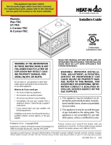
NOTE: PIPES OVERLAP 1-1/4 INCHES
(34.93mm) AT EACH JOINT.
Figure 6. DVP-Series Direct Vent Component Specifications (5-inch inner pipe / 8-inch outer pipe)
D
V
P
9
0
S
T
12-9/16
11-1/4
7-1/4
1-1/4 TYP
1/2 TYP8-9/16
DVP36
DVP48
48
24
36
4
6
DVP4
DVP6
12
DVP12
2
MIN.
DVP12A
12-3/16
MAX.
DVP24
9-7/8
45.0
O
10-1/4
DVP45
14-1/4

18
NOTE: PIPES OVERLAP 1-3/8 INCHES
(34.93mm) AT EACH JOINT.
Figure 7. SL D-Series Direct Vent Component Specifications (4-inch inner pipe / 6 5/8-inch outer pipe)
120”
(3048mm)
24”
(610mm)
36”
(914mm)
60”
(1524mm)
9 1/4
6 5/8
6 1/2
6 3/8
6 1/2
9 5/8
9 5/8
6 5/8
6 3/8
8 3/4
SL-09D
12-17
SL-12/17D (SL12-17D)
SL-24D
SL-36D
SL-48D
47 3/4
35 3/4
23 3/4
SL-45D
SL-90D
SL-17/24D
(SL17-24D)
17-24
SL-06D
SL-12D
5 3/4
6 5/8
6 1/2
11 3/4
SL-FLEX-2
SL-FLEX-10
SL-FLEX-5
SL-FLEX-3

19
!
Figure 8. Vent System Components and Termination Kits
Step 3. Installing the Vent System
A. Vent System Approvals
These models have vent starting collars on both the top
and the back of the unit. Depending upon the installation,
decide which ONE set of starting collars will be used to
attach the vent system. The starting collar sealing cap must
remain on the starting collar NOT used.
These models use SL-D-series, direct vent components
when using the TOP vent collars. This pipe is tested and
listed as an approved component of the fireplace. The pipe
is tested to be run inside an enclosed wall. There is no
requirement for inspection openings at each joint within the
wall. There is no required pitch for horizontal vent runs.
These models also use DVP-series direct vent components
when using the REAR vent collars.
The flame and ember appearance may vary based on the
type of fuel burned and the venting configuration used.
Vent System Termination Kits Vent System Components
WARNING: YOU MUST NOT MIX DVP-SERIES
AND SL D-SERIES COMPONENTS IN ANY VENT
SYSTEM CONFIGURATION.
Identifying Vent Components
Approved vent system components are labeled for identifi-
cation. NO OTHER VENTING SYSTEMS OR COMPO-
NENTS MAY BE USED. Detailed installation instructions
are included with each vent termination kit and should be
used in conjunction with this Installers Guide. Figure 8
shows vent system components and terminations.
The vent systems installed on this gas fireplace may in-
clude one, two, or three 90° elbow assemblies. The rela-
tionships of vertical rise to horizontal run in vent configura-
tions using 90° elbows MUST BE strictly adhered to. The
rise to run relationships are shown in the venting drawings
and tables. Refer to the diagrams on the next several pages.
NOTE: Two 45° elbows may be used in place of one
90° elbow. Maximum and minimum rise to run ratios
must always be maintained in the vent system when
using 45° elbows.
* For use with flex vent only.
*
**
(Required
to have a
minimum of 3
feet of vertical
in the vent
system)
(There MUST be a 25%
reduction in total H
when using the snorkel
cap except when using
the simple up and out
installation (see Fig. 9)
(For use with both DVP
and SL-D venting)
HORIZONTAL
TERMINATION
WALL
FIRESTOP
90 DEGREE
ELBOW
VERTICAL
TERMINATION
STORM COLLAR
ROOF FLASHING
HORIZONTAL PIPE
SUPPORT
PIPE LENGTH
WALL BRACKET
CEILING
FIRESTOP
SLK-991DA
SLK-01TRD
SLK-01TRF
DVP-TVHW
SL D-SERIES
DVP-SERIES
SL-FLEX2-01TRF
(SL-Series)
(SL-Series)
DVP-TRAP
DVP-TB1
DVP-TV
PVK-80
SLK-SNKD

20
STRAIGHT UP
VERTICAL VENTING
V (FT.)
45' MAX.
Figure 10.
Straight up Vertical Venting
Use SL D-Series
components only.
NOTE: For vertical venting
over 20 feet a restrictor
plate is recommended for
improved flame appearance.
STRAIGHT OUT HORIZONTAL VENTING
H
Max. Run
36" (914 mm)
Use DVP-Series
components only.
Figure 11. Straight Out Horizontal Venting
H
90-DEGREE
ELBOWS
Use two 900 elbows for corner installations.
The use of two 900 elbows in a corner installa-
tion will affect space requirements (see Fig. 4)
Figure 9.
Flex Vent
The flex vent must be supported with the spacing between
support intervals not exceeding 4 feet, with no more than ½
inch sag between supports.
A support is required at each change in venting direction,
and in any location where it is necessary to maintain the
necessary clearance to combustibles. A simple “up and out”
installation (Figure 9) requires only enough support to main-
tain the necessary clearance to combustibles. However, the
vent attachment point and the firestop location are consid-
ered to be supports.
3” CLEARANCE TERMINATION
CAP
FLEX-VENT
1”
CLEARANCE
V
CAP
/