
Dry Vacuum System
Part Numbers V3, V5, V7, 2V3, 2V3CT, 2V5, 2V5CT, 2V7, 3V5 and 4V5
PRE-INSTALLATION GUIDE
Doctor: __________________________________________________
Address: __________________________________________________
Phone#: __________________________________________________
Dealer: __________________________________________________
Dealer Address: __________________________________________________
All installations must conform to local codes.
All pumps comply with NFPA 99C level 3 requirements.
System being installed: (AS CHECKED)
qV3 qV5 qV7 q2V3 q2V3CT
q2V5 q2V5CT q2V7 q3V5 q4V5

Physical Characteristics
Master Controller
Assembly
Tanks Typical V3, V5 or V7 System Pump Configurations
MT10 / MT12
10 Gallon
CT20 / CT22
Continuum
MT10 / MT12 Tank Stacked onto
One V3, V5 or V7 Pump
One V3, V5 or V7
Pump
Two V3, V5 or V7
Pumps Stacked
Three
V5 Pumps Stacked
Width 13.5 in. (34 cm) 29 in. (74 cm) 25 in. (64 cm) 29 in. (74 cm) 25 in. (64 cm) 25 in. (64 cm) 25 in. (64 cm)
Depth 3 in. (8 cm) 22 in. (56 cm) 23 in. (58 cm) 23 in. (58 cm) 21 in. (53 cm) 21 in. (53 cm) 21 in. (53 cm)
Height 11 in. (28 cm) 33 in. (84 cm) 50 in. (127 cm) 50 in. (127 cm) 17 in. (43 cm) 34 in. (86 cm) 51 in. (130 cm)
Weight 13 Lbs. (6 kg) 75 Lbs. (34 kg) 150 Lbs. (68 kg) 220 Lbs. (100 kg) 145 Lbs. (66 kg) 290 Lbs. (132 kg) 435 Lbs. (197 kg)
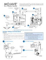
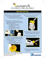
MOJAVE SYSTEM CONFIGURATIONS
Gas/Liquids/
Solids
From
Treatment
Room
Exhaust to
Outside Vent
V3, V5 or V7
Vacuum Pump
*Heat
Exchanger
Gate
Valve
Check
Valve
Sewer
Drain
MT10
Separator
Tank
Gas
Typical MOJAVE System Installation
Liquids/Solids
System Components
V3 V5 V7 2V3 2V3CT 2V5 2V5CT 2V7 3V5 4V5
V3 Pump Assembly 1 0 0 2 2 0 0 0 0 0
V5 Pump Assembly 0 1 0 0 0 2 2 0 3 4
V7 Pump Assembly 0 0 1 0 0 0 0 2 0 0
MT10 / MT12 Tank Assembly 1 1 1 1 0 1 0 0 0 0
CT20 / CT22 Tank Assembly 0 0 0 0 1 0 1 1 1 1
Master Controller Assembly 1 1 1 1 1 1 1 1 1 1
Maximum Users 5 7 10 10 10 14 14 20 20 25
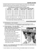
Recommended Number of Simultaneous HVE/SE Users
V3 V5 V7 2V3 or
2V3CT
2V5 or
2V5CT 2V7 3V5 4V5
HVE SE HVE SE HVE SE HVE SE HVE SE HVE SE HVE SE HVE SE
5+ 0 7+ 0 10 + 0 10 + 0 14 + 0 20 + 0 20 + 0 25 + 0
4 + 2 6 + 2 9 + 2 9 + 2 13 + 2 18 + 4 18 + 4 20 + 10
2 + 6 5 + 4 7 + 6 7 + 6 12 + 4 13 + 14 13 + 14 18 + 14
0 + 10 4+ 6 5 + 10 5 + 10 9 + 10 10 + 20 10 + 20 13 + 24
0 + 14 3 + 14 3 + 14 6 + 16 8 + 24 8 + 24 10 + 30
Note:
1 HVE = 2 SE’s
1 HVE = 2 Nitrous Scavengers
1 + 18 1 18 2 + 24 5 + 30 5 + 30 8 + 34
0 + 20 0 20 0 + 28 0 + 40 0 + 40 0 + 50
* MOJAVE Systems are available with or
without a Heat Exchanger. Systems not
using a Heat Exchanger are identified
with the “-NHE” sux in the associated
part number.

11 in.
(28 cm)
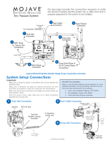
Master Controller Assembly Dimensions
10 in.
(24 cm)
11 in. (28 cm)
13.5 in. (34 cm)
3 in.
(8 cm)
V3, V5 and V7 Vacuum Pump Dimensions
17 in.
(43 cm)
25 in.
(64 cm)
21 in.
(53 cm)
17.5 in.
(44 cm)
2V3 or 2V5 System Installation
Recommended Stacked Pumps with Tank on Side
33 in.
(84 cm)
34 in.
(86 cm)
V3, V5 and V7 System Dimensions
23 in.
(58 cm)
50 in.
(127 cm)
2V7, 2V3CT or 2V5CT System Installation
Recommended Stacked Pumps with CT20 / CT22 Tank on Side
34 in.
(86 cm)
50 in.
(127 cm)
MT10 / MT12 10 Gallon Tank Dimensions
22 in.
(56 cm)
29 in.
(74 cm)
33 in.
(84 cm)
ASSEMBLY DIMENSIONS
CT20 / CT22 Continuum Tank Dimensions
42 in.
(107 cm)
25 in. (64 cm)
23 in.
(58 cm)
23 in.
(58 cm)
5.5 in.
(14 cm)
22 in.
(56 cm)
Important:
The Master Controller is mounted on the front of the MT10 / MT12 or CT20 / CT22
tank chassis. Never stack a CT20 /CT22 Tank on top of any Pump. Never stack a
Pump on top of any Tank. Recommend pumps only be stacked a maximum of two
high. All units shipped with all leveling feet set to lowest position.

SITE REQUIREMENTS
Electrical V3 & V5 V7 2V3 & 2V3CT 2V5 & 2V5CT 2V7 3V5 4V5 Master Controller
Voltage Rating Volts AC All pumps 220 Volts Single Phase AC, 50/60 Hz 120 / 220
Voltage Minimum/Maximum 198/242 Volts AC All pumps 108/132 Volts AC or
198/242 Volts AC
Wire Size AWG Minimum
Gauge
#12 AWG
(Qty 1)
#10 AWG
(Qty 1)
#12 AWG
(Qty 2)
#12 AWG
(Qty 2)
#10 AWG
(Qty 2)
#12 AWG
(Qty 3)
#12 AWG
(Qty 4) #14 AWG
Minimum Panel Breaker
Rating 20A 30A 20A (Qty 2) 20A (Qty 2) 30A (Qty 2) 20A (Qty 3) 20A (Qty 4) 15A
Incoming Power Hard wire Connection (Each pump is supplied a 6 foot BX cable)
NEMA 5-15R for 120V
NEMA 6-15R for 220V
(Supplied 10-ft. line cord)
Remote
(Low Voltage Wiring) #18 AWG (Qty 4) Wire Connection between the MMC and the Remote Switch Panel .
Optional Buck Boost
Transformer 67002 67000-1 2X 67002 or 1X 67000-1 2X 67000-1 3X 67002 4X 67002 67002 or 67005
Plumbing V3 V5 V7 2V3 & 2V3CT 2V5 & 2V5CT 2V7 3V5 4V5
Exhaust Vent Pipe Using Heat Exchanger 2” PVC
Sch. 40
2” PVC
Sch. 40
2” PVC
Sch. 40
One 3” or two
2” PVC Sch. 40
One 3” or two
2” PVC Sch. 40
One 3” or two
2” PVC Sch. 40
One 4” or three 2”
PVC Sch. 40
Two 3” or four
2” PVC Sch. 40
Exhaust Vent Pipe Not Using Heat
Exchanger (See note 1) 2” Metal Pipe 2” Metal Pipe 2” Metal Pipe One 3” or two
2” Metal Pipe
One 3” or two
2” Metal Pipe
One 3” or two
2” Metal Pipe
One 4” or three
2” Metal Pipe
Two 3” or four
2” Metal Pipe
Minimum Suction Line Pipe 1” PVC
Sch. 40
1 ½” PVC
Sch. 40
2” PVC
Sch. 40
1 ½” PVC
Sch. 40
2” PVC
Sch. 40
3” PVC
Sch. 40
3” PVC
Sch. 40
3” PVC
Sch. 40
Maximum Suction Line Pipe (See note 2) 1 ½” PVC
Sch. 40
2” PVC
Sch. 40
2 ½” PVC
Sch. 40
2” PVC
Sch. 40
2 ½” PVC
Sch. 40
4” PVC
Sch. 40
4” PVC
Sch. 40
4” PVC
Sch. 40
Riser Pipe ½” PVC
Sch. 40
½” PVC
Sch. 40
½” PVC
Sch. 40
½” PVC
Sch. 40
½” PVC
Sch. 40
½” PVC
Sch. 40
½” PVC
Sch. 40
½” PVC
Sch. 40
Vacuum Line Termination 1 ½” FNPT 1 ½” FNPT 2” FNPT 2” FNPT 2” FNPT 2” FNPT 2” FNPT 2” FNPT
Branch Line Pipe Size requirement of Branch piping
diers by the number of operatories
being serviced.
Up to three operatories use 1" PVC Schedule 40.
Four to six operatories use 1 ½” PVC Schedule 40.
More that six operatories use 2" PVC Schedule 40
Drain Line Pipe 1 ½” PVC Schedule 40
Wash-Out Water Line ½” FNPT Shut-off Valve
NOTES
1. Recommended pipe used with models without a heat exchanger includes wrought iron pipe (black & galvanized) or copper pipe type M. Insulate
metal pipe in utility room to avoid adding heat to the room. Insulation must be rated for a minimum of 300°F continuously.
2. Use maximum internal diameter for the main line when preparing any new installation.

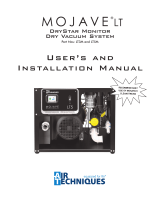
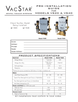
TYPICAL EQUIPMENT ROOM FLOOR PLAN LAYOUT
48"
4"
4"
107"
20"
24"
Sewer Drain
12"
4"
4"
80"
Pump/Tank
Connection Manifold
MT10 or CT20
Tank
Single or
Stacked Pumps
(V3, V5 or V7)
23"
Single or
Stacked Pumps
(V3, V5 or V7)
76"
62"
1"
12"
24"
4"
B
A
A
D
E
J
H
K
C
G
F
Open
Drain Pipe
Closed Vented
Drain
OR
Detail C: Sewer Drain Options
A. PUMP INSTALLATION SPACE - Area for stacked or side by side pump installation. Keep 4 inch space from walls. Only stack up to 2 pumps in one area.
B. TANK INSTALLATION SPACE - Area for typical side by side tank installation. Keep 4 inch space from walls. Never install the CT20 / CT22 tank on top of a pump.
C. SEWER DRAIN - Provide a drain for the removal of waste liquids from the MOJAVE tank. Use an open drain pipe (1 ½” inch P-Trap with 1 inch air gap or oor
sink) or a closed vented drain. See detail C for options.
D. TANK WASHOUT - Provide a water source terminated with a ½” inch FNPT shut-off valve providing water pressure between 20 and 100 psi for daily tank
washout. Valve location must be no more than 10 feet from the tank installation to allow connection of supplied 10-foot 3/8-inch Poly tubing to the tank
washout port. Provisions for backflow prevention may be required. Check local code requirements.
E. MASTER CONTROLLER ELECTRIC OUTLET - Master Controller requires a dedicated standalone 120V, 5 AMP or 220V, 5 AMP grounded receptacle.
F. PUMP ELECTRIC SERVICE - Each Mojave pump is wired directly with a dedicated 220V, 20 AMP, (30 AMP for V7) single phase 60 Hz circuit. If Main Circuit
panel is not located in equipment room, a disconnect box with approved ground is needed for each pump. Disconnect boxes should be mounted no more
than 3 feet of each other and 3 feet of installation center line.
G. SUB FLOOR INSTALLATION VACUUM LINE - See Plumbing Requirements for connection to tank input via supplied hose.
H. OVERHEAD INSTALLATION VACUUM LINE - See Plumbing Requirements for connection to tank input via supplied hose.
J. HEAT EXHAUST - See Plumbing Requirements for the exhaust vent line required for specific Mojave configurations. Use metal pipe on systems whenever the Heat
Exchanger is removed. Schedule 40 pipe can normally be used on typical Mojave configuration installations with a Heat Exchanger. When installing multiple
pumps, see Mojave exhaust line options page.
K. PUMP/TANK MANIFOLD - User fabricated to connect 3 or 4 pumps to a tank. Used with 3V5 and 4V5 systems. See Pump/Tank Connection Manifold.
INSTALLATION NOTES:

TREATMENT ROOM PLUMBING INSTALLATIONS
q Use only 45° elbows to make turns in main line.
q Make sure to use the proper pipe type for associated system.
q If piping is diverted to clear an obstruction, DO NOT MAKE A TRAP.
See detail A, Main Line Turn Connections.
q DO NOT use standard 90° elbows.
SUB FLOOR INSTALLATION -
Recommended system installation layout should be used
whenever possible.
Notes:
1. 10-foot Maximum Height from Main
Line to Tank.
2. Consult Dental Unit Manufacturer's
Guidelines for correct reduced size
and height of termination of vacuum
line inside junction box.
3. Limit branches. Orient main line
under junction box or cabinet.
4. When piping line is above 3/4" I.D.
or larger, use 45° Y's & elbows only.
5. Recommend installing separate line
connection for scavenger when using
Nitrous scavengers in overhead
piping installations.
Minimum Slope:
1/4 inch per 10 Feet
Interior Wall
1/2-Inch Diameter Riser
10-FT Maximum Height
from Riser Trap to Main
Line
OVERHEAD INSTALLATION -
Alternate system installation layout should be used only when
unable to use the sub-floor plumbing layout.
Ceiling
Junction
Box
See Note 2.
1/2 - Inch Diameter Riser Minimum Slope:
1/4 inch per 10 Feet Main Line Riser for connection to
tank input. See Note 1.
MAIN LINE See Notes 2, 3 & 4.
Junction
Box
See Note 2.
MAIN LINE
See Notes 2, 3
4 & 5.
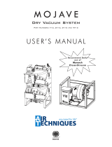
CONNECTOR DETAILS - ALL INSTALLATIONS
Ceiling
Important:
All installation pipes and fittings provided by plumber.
All installations must conform to local codes.
Interior Wall
Main
Line Turn
Connection
See A.
Sub Floor
Riser
Connection
See B.
Riser Trap
See D.
Overhead Riser
See C.
Sub Floor Riser to Main Line Detail
1/2 Inch Riser
45°Elbow
45°Y
1/2 Inch
Diameter
To
Tank
45°Elbow
1" Min
Main
Line
Overhead Riser to Main Line Detail
(Prevents liquids from draining down the 1/2” riser.)
Main Line Turn Connections
45° Elbow
45° Elbow
Clearing &
Obstruction
Making
Turns
Riser Trap Detail (45° Elbows)
1/2-Inch
Riser
To Main
Line
1/2-Inch
To
Dental Unit
Junction
Box
45°ELL
45°Y
To
Tank
Main
Line
1/2 Inch Riser
To Dental Unit
Junction Box
AB C D

PUMP/TANK CONNECTION MANIFOLD
MEDICAL ELECTRICAL EQUIPMENT
WITH RESPECT TO ELECTRICAL SHOCK, FIRE, MECHANICAL
AND OTHER SPECIFIED HAZARDS ONLY
IN ACCORDANCE WITH UL-60601-1, CAN/CSA C22.2 NO.601.1 66CA
C
L
A
S
S
I
F
I
E
D
Pump/Tank Connection Manifold Using Accessory Kit
Flat Side Installed
Facing Up
Compression
Gasket Connector
to Pump 1-1/2” FNPT to
Sanitary Tee
Sanitary Tee with 1-1/2” FNPT End
Fitting. 3 or 4 depending on system
configuration. (Supplied by Plumber)
3” PVC or Copper
Tubing & Elbow
(Supplied by Plumber)
1.5 ft
3 or 4 Supplied
Check Valves -
See Kit
P/N MIK4
Check Valve Installed
Flat Side Facing Up
Horizontal to Floor
3” PVC or Copper
Clean-out Plug Used with P/N MIK4
(Supplied by Plumber)
A
i
r
F
l
o
w
2” PVC or Copper
Tubing for Tank Hose
(Supplied by Plumber)
Check Valve Side
View
CT20 TANK INLET CONNECTION DETAIL
6-inch
Riser
Customer-
Supplied Tee
Connector
3/4
FNPT
2” Flexible
Coupling
Connector
1/4-inch Vacuum
Sample Port to
Master Controller
Reducing
Bushing
Swivel
Elbow
2” Pipe for
connection
to Facility
Piping from
Operatory.
Note: Hang using at least 3 pipe
supports supplied by Plumber.
Hoses From
Manifold To Pumps
Hose Between Manifold
and CT20 / CT22 Tank
Secured by Flexible
Couplers
V3, V5 & V7
PUMP HOSE
CONNECTION
DETAIL
Hoses From
Manifold To Pumps
Hose Between Manifold and
CT20 / CT22 Tank Secured
by Flexible Couplers
Hose from Manifold Connected to Pump
via Air Input Filter Gasket Connector
1 ft

4" PVC
SCH. 40
2" PVC
CUT TO LENGTH
4" x 4" x 2" WYE
4" PVC
CUT TO LENGTH
3" x 3" x 2" WYE
4" TO 3" REDUCER
2" PVC
CUT TO LENGTH
3" TO 2" REDUCER
3" PVC
CUT TO LENGTH
DRIP LEG ASSEMBLY
3" PVC
SCH. 40
3" x 3" x 2" WYE
3" TO 2"
REDUCER
3" PVC
CUT TO LENGTH
2" PVC
CUT TO LENGTH
2" PVC
CUT TO LENGTH
2" PVC
SCH. 40
2" EXHAUST LINE 4" EXHAUST LINE3" EXHAUST LINE
*NOTE:
Do not use mutliple 2" WYE assemblies together with a singe 2" exhaust line for multi-pump systems.
MOJAVE Exhuast Line Options
ONLY USE ONE
2" WYE PER LINE*
2" EXHAUST LINE
MODEL#
QTY
V3, V5, V7 1x
2V3, 2V5, 2V7
2x
3V5
3x
4V5
4x
3" EXHAUST LINE
MODEL#
QTY
2V3, 2V5, 2V7
1x
4V5
2x
4" EXHAUST LINE
MODEL#
QTY
3V5
1x
Make sure to take into account pump locations before assembling manifold.
2" PVC
CUT TO LENGTH
2" x 2" x 2" WYE
2" PVC
CUT TO LENGTH
2" x 2" x 2" WYE
2" x 2" x 2" WYE
DRIP LEG ASEMBLY
BELOW LINE INCLUDED.
ITEMS ABOVE
LINE SUPPLIED BY
PLUMBER
MOJAVE EXHAUST LINE OPTIONS

NOTES

NOTES

NOTES

HEAT EXHAUST CONNECTION NOTES
1. VENT LINE - The exhaust vent line required for MOJAVE systems using
the Heat Exchanger and systems without the Heat Exchanger (-NHE units)
have different requirements.
Use metal pipe on systems without a Heat Exchanger while PVC
Schedule 40 pipe can be used on systems with a Heat Exchanger.
Do not make a trap in the exhaust vent piping. Do not use 90 ο fittings.
Also see Exhaust Vent Protection and Ventilation Requirements below.
2. V3, V5 & V7 PUMP EXHAUST VENT CONNECTION - Connection between
the pump and exhaust vent piping is typically made via the supplied 2-inch
Black Flex tubing.
3. EXHAUST VENT ASSEMBLY - The supplied assembly must be
installed at the lower end of the vent pipe to collect condensation
produced during pump operation. The bottom of the Y connector
should be located 18 inches from oor. Attach the drain tube to the drip
leg quick-connect tting to allow drainage into oor drain/sink.
EXHAUST VENTILATION REQUIREMENTS
V3,V5 & V7 Pump Heat Exchanger Connection
Exhaust Vent Assembly
supplied with Tank
Accessory kit.
See Detail & Note 3.
Exhaust Vent
See Note 1.
Typical Flex
Tubing
See Note 2.
V3 or V5 Pump Top View
Vent Pipe
*Heat
Exchanger
17-Inch Long
Flex Tubing
4”
Drip Leg Detail View
2” Flexible Coupler
2” PVC Reducing Bushing
3/4” MNPT X 1/4” FNPT PVC Bushing
1/4” MNPT X 1/4” Push Elbow
35”
18”
Exhaust Vent Protection.
If the exhaust piping is venting to the outside of the building, precautions must be taken to protect
the equipment room from weather elements and animal intrusion. This can be accomplished by
using one of the three methods shown on the right.
Wall-Mounted Outside
Vent Protection
Shroud &
Screen
Roof-Mounted Outside Vent Protection
Shroud &
Screen
Screen
Exhaust Vent Requirements.
The MOJAVE equipment must be used in a controlled-temperature environment. Maintain
equipment room temperature between 40 and 105 degrees Fahrenheit. An exhaust fan is
necessary if room temperature is not maintained by other methods.
Adequate forced ventilation must be provided across the unit by placing an appropriate
exhaust fan opposite an equivalent air intake vent . The fan should be placed higher than the
associated intake vent. Recommended minimum exhaust fan requirements for each MOJAVE
unit are listed to the right.
Note: Only 1 pump is running when operating in idle mode.
MOJAVE
Unit
Watts
(Idle)
Watts
(Max)
BTU/Hr
(Idle)
BTU/Hr
(Max)
V3 886 1,601 3,021 5,462
V5 886 2,245 3,021 7,660
V7 1,200 2,245 3,021 7,660
2V3 & 2V3CT 886 3,202 6,042 10,924
2V5 & 2V5CT 886 4,490 6,042 15,320
2V7 See
Note 1,200 4,490 6,042 15,320
3V5 886 6,735 9,063 22,980
4V5 886 8,980 12,084 30,640
Corporate Headquarters
1295 Walt Whitman Road | Melville, New York 11747- 3062
Phone: 800-247-8324 | Fax: 888-247-8481
www.airtechniques.com MOJAVE is a trademark of Air Techniques, Inc.
© 2014 Air Techniques, Inc. • P/N H5187, Rev. U •September 2021
* MOJAVE Systems are available with or without a Heat Exchanger.
Systems not using a Heat Exchanger are identified with the “-NHE”
suffix in the associated system part number.
-
 1
1
-
 2
2
-
 3
3
-
 4
4
-
 5
5
-
 6
6
-
 7
7
-
 8
8
-
 9
9
-
 10
10
-
 11
11
-
 12
12


Air Techniques Mojave V5M Installation guide
- Type
- Installation guide
- This manual is also suitable for
Ask a question and I''ll find the answer in the document
Finding information in a document is now easier with AI
Related papers
-
 Air Techniques Mojave LT Series Owner's manual
-
 Air Techniques Mojave V3M Owner's manual
-
 Air Techniques Mojave LT Series Owner's manual
-
 Air Techniques Mojave Installation Kits & Accessories Owner's manual
-
 Air Techniques Utility Stacking Racks Owner's manual
-
 Air Techniques Monarch CleanStream Evacuation System Cleaner Owner's manual
-
 Air Techniques Mojave V3M Operating instructions
-
 Air Techniques VacStar 20 Owner's manual
-
 Air Techniques VacStar 20 Owner's manual
-
 Air Techniques VacStar 20 User manual


Other documents
-
K2 Pumps AQC150K User guide
-
RC4WD Mojave Body Owner's manual
-
Camco 8615932 Owner's manual
-
 Thermo Fisher Scientific SITE User guide
-
Midmark POWERMAX Installation guide
-
Rinnai TRS05EN Installation guide
-
Aerco AM 750B User manual
-
Raypak XVers L 406L-856L Type H Operating instructions
-
Weil-McLain SVF Stainless Vertical Firetube (1500–3000 MBH) User manual
-
