Moxa ioThinx 4510 Series User manual
- Category
- Networking
- Type
- User manual

ioThinx 4510 Series User’s Manual
Version 5.0, April 2021
www.moxa.com/product
© 2021 Moxa Inc. All rights reserved.

ioThinx 4510 Series User’s Manual
The software described in this manual is furnished under a license agreement and may be used only in accordance
with the terms of that agreement.
Copyright Notice
© 2021 Moxa Inc. All rights reserved.
Trademarks
The MOXA logo is a registered trademark of Moxa Inc.
All other trademarks or registered marks in this manual belong to their respective manufacturers.
Disclaimer
Information in this document is subject to change without notice and does not represent a commitment on the part of
Moxa.
Moxa provides this document as is, without warranty of any kind, either expressed or implied, including, but not
limited to, its particular purpose. Moxa reserves the right to make improvements and/or changes to this manual, or to
the products and/or the programs described in this manual, at any time.
Information provided in this manual is intended to be accurate and reliable. However, Moxa assumes no responsibility
for its use, or for any infringements on the rights of third parties that may result from its use.
This product might include unintentional technical or typographical errors. Changes are periodically made to the
information herein to correct such errors, and these changes are incorporated into new editions of the publication.
Technical Support Contact Information
www.moxa.com/support
Moxa Americas
Toll-free: 1-888-669-2872
Tel: +1-714-528-6777
Fax: +1-714-528-6778
Moxa China (Shanghai office)
Toll
-free: 800-820-5036
Tel:
+86-21-5258-9955
Fax:
+86-21-5258-5505
Moxa Europe
Tel: +49-89-3 70 03 99-0
Fax: +49-89-3 70 03 99-99
Moxa Asia
-Pacific
Tel:
+886-2-8919-1230
Fax:
+886-2-8919-1231
Moxa India
Tel: +91-80-4172-9088
Fax: +91-80-4132-1045

Safety Symbols
DANGER
Indicates a high
-risk, imminently hazardous situation which, if not avoided, will result in death or serious
injury.
WARNING
Indicates a moderate
risk, which, if not avoided can cause a potentially hazardous situation.
CAUTION
Indicates a low
-risk, potentially hazardous situation which, if not avoided, may result in minor or moderate
in
jury.
NOTE
Indicates a potential malfunction which, if not avoided, will not result in damage to property.
INFORMATION
This information is important for preventing errors.

Table of Contents
1. Preface ........................................................................................................................................ 1-1
Revision History............................................................................................................................ 1-2
Relevant Models ........................................................................................................................... 1-2
Package Contents ......................................................................................................................... 1-2
Usage Scenarios ........................................................................................................................... 1-2
Hardware and Software Requirements .............................................................................................. 1-3
Safety Precautions ........................................................................................................................ 1-3
Additional Resources ..................................................................................................................... 1-4
2. Product Overview ......................................................................................................................... 2-1
Technical Data.............................................................................................................................. 2-2
Common Specifications ........................................................................................................... 2-2
Appearance.................................................................................................................................. 2-3
Front View ............................................................................................................................ 2-3
Physical Dimensions ............................................................................................................... 2-3
LED Indicators .............................................................................................................................. 2-4
3. Hardware Installation................................................................................................................... 3-1
Wiring System and Field Power........................................................................................................ 3-2
System Power ....................................................................................................................... 3-2
Field Power ........................................................................................................................... 3-3
Wiring Ethernet Ports..................................................................................................................... 3-3
Wiring Serial Port(s) ...................................................................................................................... 3-4
Grounding the Unit ........................................................................................................................ 3-4
Connecting the System Power Ground ....................................................................................... 3-4
Connecting the Field Power Ground ........................................................................................... 3-5
Mounting the Unit ......................................................................................................................... 3-6
Installing the Unit on a DIN Rail ............................................................................................... 3-6
Removing the Unit from a DIN Rail............................................................................................ 3-7
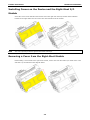
Installing Covers on the Device and the Right-Most I/O Module ...................................................... 3-8
Removing a Cover from the Right-Most Module ........................................................................... 3-8
Horizontal Installation ............................................................................................................. 3-9
Powering on the Unit ..................................................................................................................... 3-9
4. Software Tools ............................................................................................................................. 4-1
Preparing Software Tools................................................................................................................ 4-2
Connecting Web Console ......................................................................................................... 4-2
Preparing IOxpress Utility ........................................................................................................ 4-2
Preparing Moxa CLI Configuration Tool....................................................................................... 4-2
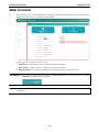
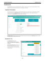
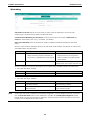
Web Console ................................................................................................................................ 4-3
Dashboard ............................................................................................................................ 4-4
System ................................................................................................................................ 4-7
Security .............................................................................................................................. 4-10
Network .............................................................................................................................. 4-14
Module ................................................................................................................................ 4-15
I/O ..................................................................................................................................... 4-17
Serial Port ........................................................................................................................... 4-27
Internal Register ................................................................................................................... 4-31
Protocol .............................................................................................................................. 4-32
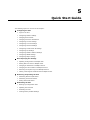
5. Quick Start Guide ......................................................................................................................... 5-1
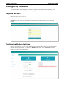
Configuring the Unit ...................................................................................................................... 5-2
Login to the Unit .................................................................................................................... 5-2
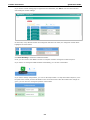
Configuring Module Settings .................................................................................................... 5-2
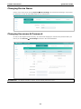
Changing Device Name ........................................................................................................... 5-4
Changing Username & Password ............................................................................................... 5-4
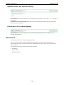
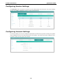
Configuring Service Settings .................................................................................................... 5-5
Configuring Account Settings ................................................................................................... 5-5
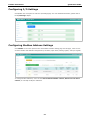
Configuring Network Settings ................................................................................................... 5-6
Configuring Serial Port & IR Settings ......................................................................................... 5-6
Configuring I/O Settings.......................................................................................................... 5-7
Configuring Modbus Address Settings ........................................................................................ 5-7
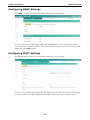
Configuring SNMP Settings ...................................................................................................... 5-8
Configuring MQTT Settings ...................................................................................................... 5-8
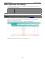
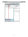
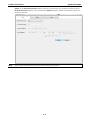
Mass-deploying the Settings ........................................................................................................... 5-9
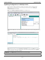
Updating Configuration to Multiple Units.................................................................................... 5-12
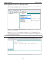
Setting Date and Time to Multiple Units .................................................................................... 5-13
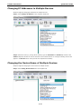
Changing IP Addresses to Multiple Devices ................................................................................ 5-14
Changing the Device Name of Multiple Devices ........................................................................... 5-14
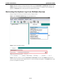
Retrieving the System Log from Multiple Devices ........................................................................ 5-15
Getting a Self-signed Certificate from Multiple Devices ................................................................ 5-16

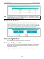
Monitoring & Operating the Unit ..................................................................................................... 5-16
Monitoring Module & I/O Status ............................................................................................... 5-17
Monitoring Connection Status .................................................................................................. 5-17
Exiting Safe Mode Status........................................................................................................ 5-18
Maintaining the Unit ..................................................................................................................... 5-18
Backing up Configuration Files................................................................................................. 5-18
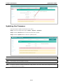
Updating the Firmware........................................................................................................... 5-19
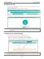
Restarting the Unit ................................................................................................................ 5-20
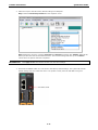
Loading Factory Default Settings ............................................................................................. 5-20
6. Tutorials ...................................................................................................................................... 6-1
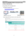
How to Use Modbus TCP to Connect to the ioThinx 4510 Series ............................................................. 6-2
Using Modbus TCP via Modbus Poll ............................................................................................ 6-2
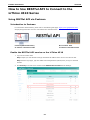
How to Use RESTful API to Connect to the ioThinx 4510 Series ............................................................. 6-7
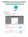
Using RESTful API via Postman ................................................................................................. 6-7
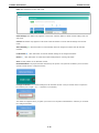
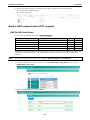
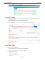
Send a GET request and a PUT request ...................................................................................... 6-9
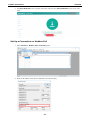
How to Use MQTT to Connect to the ioThinx 4510 Series..................................................................... 6-11
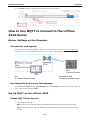
Broker Settings on the Computer ............................................................................................. 6-11
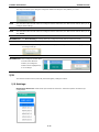
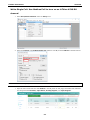
Set Up MQTT on the ioThinx 4510 ............................................................................................ 6-11
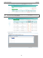
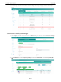
Publisher and Subscriber Settings ............................................................................................ 6-14
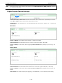
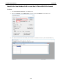
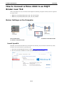
How to Connect ioThinx 4510 to an MQTT Broker over TLS .................................................................. 6-16
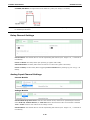
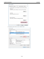
Broker Settings on the Computer ............................................................................................. 6-16
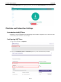
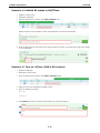
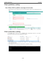
Client (publisher) setting ........................................................................................................ 6-20
Client (subscriber) setting ...................................................................................................... 6-20
A. Appendix...................................................................................................................................... A-1
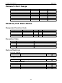
Network Port Usage....................................................................................................................... A-2
Modbus/TCP Slave Rules ................................................................................................................ A-2
Supported Function Code ........................................................................................................ A-2
Exception Code...................................................................................................................... A-2
System Registers ................................................................................................................... A-2
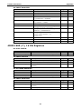
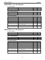
45MR-1600 (-T), 16 DIs Registers ............................................................................................ A-3
45MR-1601 (-T), 16 DIs Registers ............................................................................................ A-4
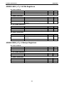
45MR-2404 (-T), 4 Relays Registers .......................................................................................... A-4
45MR-2600 (-T), 16 DOs Registers ........................................................................................... A-5
45MR-2601 (-T), 16 DOs Registers ........................................................................................... A-5
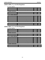
45MR-2606 (-T), 8 DIs, 8 DOs Registers .................................................................................... A-6
45MR-3800 (-T), 8 AIs Registers .............................................................................................. A-7
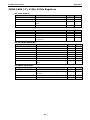
45MR-3810 (-T), 8 AIs Registers .............................................................................................. A-7
45MR-4420 (-T), 4 AOs Registers ............................................................................................. A-8
45MR-6600 (-T), 6 RTDs Registers ............................................................................................ A-8
45MR-6810 (-T), 8 TCs Registers .............................................................................................. A-9
45MR-7210(-T), System and Field Power Input Registers .............................................................. A-9
SNMP Rules ................................................................................................................................. A-9
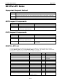
RESTful API Rules ........................................................................................................................A-10
Supported Request Method .....................................................................................................A-10
GET Request Components ......................................................................................................A-10
PUT Request Components.......................................................................................................A-10
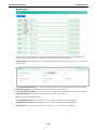
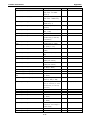
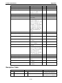
RESTful API List ....................................................................................................................A-10
Exception Code.....................................................................................................................A-12
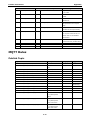
MQTT Rules ................................................................................................................................A-13
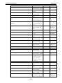
Publish Topic ........................................................................................................................A-13
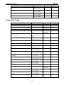
Subscribe Topic ....................................................................................................................A-16
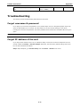
Troubleshooting ...........................................................................................................................A-17
Forgot username & password ..................................................................................................A-17
Forgot IP address of the unit ...................................................................................................A-17
Failed to update firmware .......................................................................................................A-18
Failed to update configuration .................................................................................................A-19
Failed to access the unit through IP address & IOxpress ..............................................................A-19
Failed to enter System Ready Mode..........................................................................................A-19
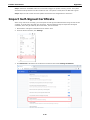
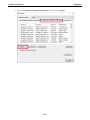
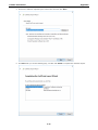
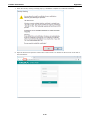
Import Self-Signed Certificate ........................................................................................................A-20
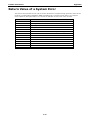
Return Value of a System Error ......................................................................................................A-24


ioThinx 4510 Series Preface
1-2
Revision History
Version Change Date
v1.0 First Release 2018-11-12
v2.0 1. Added 45M R-7210
2. Added MQTT
3. Added HTTPS
4. Added more mass deploy functions in IOx press
2019-05-10
v2.1 1. Added power calculation links 2019-08-22
v3.0 1. Added 45M R-4420
2. Added SNMP Trap and Inform
2019-09-11
v4.0 1. Added SP/FP description
2. Added Modbus TCP, RESTful , MQTT tutorial
2020-02-10
V5.0 1. Modify description of HTTPS
2. Add LLDP
3. Add system error code
4. Modify profile information of Modbus RTU
5. Update content of Access IP
6. Update content of the RESTful API rule
2021-02-25
Relevant Models
This document is only applicable to the models listed below.
Model Name Description
ioThinx 4510 Advanced I/O, Ethernet network adapter, 3-in-1 serial port(s), -
20 to 60°C operating
temperature
ioThinx 4510-T Advanced I/O, Ethernet network adapter, 3-in-1 serial port(s), -
40 to 75°C operating
temperature
Package Contents
The following items are included in the product package.
• The ioThinx 4510 device
• Quick installation guide (Printed)
• Warranty card
Usage Scenarios
The ioThinx 4510 Series can be used for the following applications:
1. PLC I/O expansion
The ioThinx 4510 Series can be used to expand the number of I/O points on a PLC.
2. Remote I/O
The ioThinx 4510 Series can be accessed by master software, such as SCADA software, using IT or OT
protocols to collect I/O data.
3. Modbus Gateway
The ioThinx 4510 Series has one or more serial ports to connect serial devices. It collects serial data
using a Modbus RTU master protocol, which can be accessed by a PLC or master software with IT or OT
protocols.

ioThinx 4510 Series Preface
1-3
Hardware and Software Requirements
You will need the following hardware and software to use the ioThinx 4510 Series.
• A power source that provides 12 to 48 VDC, and power wires
• A PC running a Windows OS with Chrome installed and an Ethernet cable
• 45MR modules, if available
• IOxpress software utility (optional)
• Moxa CLI Configuration Tool (optional)
Safety Precautions
Please observe the following safety precautions when installing and using the ioThinx 4510 Series:
DANGER
Never work on the device while the power source is switched on. Disconnect all power sources to the device
before performing installation, repair, or maintenance work.
DANGER
Disconnect the power when you want to remove or replace components, or disconnect equipment unless the
area is know
n to be free of ignitable substances.
•
If you connect or disconnect the Removable Terminal Block when field power is applied, an electrical arc
can occur. This could cause an explosion when installed in hazardous locations. Ensure that power is
removed or the area is nonhazardous before installation.
•
If you connect or disconnect wiring while the power is on, an electrical arc can occur. This could cause
an explosion in hazardous environments. Ensure that power is removed or the area is nonhazardous
before installation.
•
Do not disconnect the unit unless the power has been disconnected or the area is known to be
nonhazardous. In a hazardous area, the unit must be powered down before removing it.

ioThinx 4510 Series Preface
1-4
WARNING
This unit is sensitive
to Electrostatic Discharge, which can cause internal damage and affect operations.
Follow these guidelines when you handle this unit:
•
Touch a grounded object to discharge potential static.
•
Wear an approved grounding wristband.
•
Do not touch connectors or pins on component boards.
•
Do not touch circuit components inside the equipment.
•
Use a static-safe workstation, if available.
•
Store the device in appropriate static-safe packaging when not in use.
WARNING
Check the voltage s
upplied by the power source. Make sure the voltage provided by the power source
matches the voltage required by the device.
WARNING
Check the voltage or current of the sensors or loads. Make sure the voltage and/or curren
t indicated on the
sensors or loads corresponds to the specifications of your 45M module before you connect the device.
WARNING
Connect your device to an earthed ground.
CAUTION
Do not u
se the device if the device is already damaged. Replace defective or damaged devices to ensure
that your devices
function properly.
CAUTION
Do not attempt to repair the device yourself. If your device needs to be repaired
, return the device to
Moxa’s customer service department. Attempting to repair the device yourself could invalid
ate the device’s
warranty.
Additional Resources
Refer to the following documents for additional information.
• Datasheets for the following products:
ioThinx 4510 Series
ioThinx 4500 Series (45MR) Modules
• User’s Manual for the following products:
ioThinx 4500 (45M) Module Series
Moxa CLI Configuration Tool


ioThinx 4510 Series Product Overview
2-2
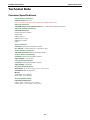
Technical Data
Common Specifications
Input/Output Interface
Expansion
Sl ots: Up to 32
Note: Compatible with the ioThinx 4500 Series (45MR) Modules only
Ethernet Interface
10
/100BaseT(X) Ports (RJ45 connector): 2, 1 MAC address (Ethernet bypass)
Ethernet Software Features
Industrial Protocols:
Modbus TCP Server (Slave)
RESTful API
SNMPv1/v2c/v3
SNMPv1/v2c/v3 Trap
SNMPv2c/v3 Inform
MQTT
Serial Interface
Connector:
Spring-type Euroblock terminal
No. of Ports: 1 x RS-232/422 or 2 x RS-485 (2 wire)
Serial Software Features
Industrial Protocols:
Modbus RTU Client (Master)
System Power Parameters
Connector:
Spring-type Euroblock terminal
Input Voltage:
12 to 48 VDC
Field Power Parameter
s
Connector: Spring-type Euroblock terminal
Input Voltage:
12/24 VDC
Physical Characteristics
Dimensions:
42.3 x 99 x 75 mm (1.67 x 3.9 x 2.95 in)
Installation:
DIN-rail mounting
Wiring:
Serial cable, 16 to 28 AWG
Power cab
le, 12 to 26 AWG
Environmental Limits
Operating Temperature:
ioThinx 4510
: -20 to 60°C (-4 to 140°F)
ioThinx 4510-T: -40 to 75°C (-40 to 167°F)

ioThinx 4510 Series Product Overview
2-3
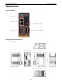
Appearance
Front View
Physical Dimensions
Unit: mm (in)

ioThinx 4510 Series Product Overview
2-4
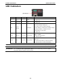
LED Indicators
Labeling
Indication
LED Qty
LED Color
LED Action
SP
System
Power
1 Green
On: power on
Off: power off
FP Field Power 1 Green
On: power on
Off: power off
RDY
System
(Kernel)
1 Green/Red
Green: system ready
Green slow blinking: booting up
Red: system error or module mismatch
Red slow blinking: loading factory default settings,
upgrading firmware, or system recovery
Red fast blinking: safe mode
Off: power off
L1/L2 Ethernet 1 for each Green/Amber
Green: 100 Mbps
Amber: 10 Mbps
Blinking: data transmitting
Off: disconnected
P1/P2 Serial 1 for each Green/Amber
Green: Tx
Ambe r: Rx
Non-simultaneous blinking: data transmitting
Off: disconnected or no data transmitting
NOTE
DO NOT DISCONNECT
THE POWER OR NETWORK CABLE when the RDY LED is blinking slowly.
INFORMATION
Refer to
Failed to Enter System Ready Mode in the troubleshooting section for addition
information about
the system recovery process.

3
3. Hardware Installation
In this chapter, we describe how to install the ioThinx 4510 Series devices.
The following topics are covered in this chapter:
Wiring System and Field Power
System Power
Field Power
Wiring Ethernet Ports
Wiring Serial Port(s)
Grounding the Unit
Connecting the System Power Ground
Connecting the Field Power Ground
Mounting the Unit
Installing the Unit on a DIN Rail
Removing the Unit from a DIN Rail
Installing Covers on the Device and the Right-Most I/O Module
Removing a Cover from the Right-Most Module
Horizontal Installation
Powering on the Unit

ioThinx 4510 Series Hardware Installation
3-2
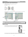
Wiring System and Field Power
Wire range: 12 to 26 AWG (Ferrule diameter: 2.0 to 0.4 mm)
Wire strip length: 10 mm
Unit: mm (in.)
The device requires two sets of power inputs. One is for the system (internal logic circuit), and the other is
for field I/O circuits.
NOTE
All I/O points have 3 kV VDC or 2 kVrms isolation with the system. We recommended using different po
wer
supplies to ensure that the system power and field power are isolated from each other.
System Power
This device requires a 12 to 48 VDC system
power input. The system
power powers this device and the expansion modules via an internal
bus, which is ga
lvanically connected to the system power supply.
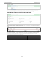
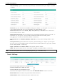
The amount of system current required to support an expansion module is 1 A. If more modules and more
power consumption is needed, an additional power module (45MR-7210) is required. Below is an example:

ioThinx 4510 Series Hardware Installation
3-3
• 10 x 45MR-1600 (59.4 mA) = 594 mA
• 5 x 45MR-3810 (187 mA) = 935 mA
The total system current is 1.594 A, which is greater than 1 A. Therefore, an additional 45MR-7210 is
needed.
NOTE
Install the 45MR
-7210 to the left hand side of the module where the power consumption would be
exceeded.
NOTE
To avoid damaging your devices, r
eset all power supplies connected to this device and 45MR-7210 modules
at the same time
.
NOTE
Click the following link to see how many 45MR
-7210 power modules you will need to support your ioThinx
4500 series application:
http://iothinxcalculator.moxa.com
Field Power
This device provides
a field power input of 12/24 VDC that passes
directly through the expansion modules and provides
a maximum
current output of 2 A.
NOTE
The 12/24 VDC field power supply can be connected directly to 45MR modules. If more connection points
are needed, purchase 45MR
-7820 (8 x FP+ and 8 x FP -) modules.
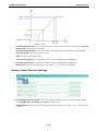
Wiring Ethernet Ports
The maximum cable length of a 10/100BaseT connection is usually stated as 100 m (350 feet), but the
actual limit for your application could be longer or shorter depending on the amount of electrical noise in the
environment. To minimize the amount of noise, Ethernet cables should not run parallel to power cables or
other types of cables that generate electrical noise. The following diagram and table shows the pin
assignments for the RJ45 Ethernet ports:
Pin Media Direct Interface Signal
1 Tx+ (transmit)
2
Tx- (transmit)
3 Rx+ (receive)
4 Not used
5 Not used
6 Rx- (receive)
7 Not used
8
Not used

ioThinx 4510 Series Hardware Installation
3-4
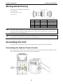
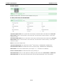
Wiring Serial Port(s)
Wire range: 16 to 28 AWG (Ferrule diameter:
1.2 to 0.3 mm)
Wire strip length: 9.0 mm
Unit: mm (in.)
Pin RS-232 RS-422 RS-485 (P1/P2)
1
TXD
TXD+
DATA1+
2 RXD TXD- DATA1-
3 RTS RXD+ DATA2+
4 CTS RXD- DATA2-
5 GND GND GND
NOTE
Connect the signal
common pin (e.g. GND pin on the serial port pin assignment) between each of the serial
device units. For insulated wire (shielding cable)
that is used to reduce electrical noise, connect the cable
shield drain wire to the chassis ground.
NOTE
To ensure
that wires are securely connected to terminal block connectors, strip 7 to 9 mm of insulation off
the ends of the wires before connecting them to the terminal block.
Grounding the Unit
This device has two ground pins. One pin is for system power and the other pin is for field power.
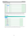
Connecting the System Power Ground
The system power ground connector is at the back of the unit. Once the device has been installed on a DIN
rail, the system power ground connector will connect to the DIN rail.

ioThinx 4510 Series Hardware Installation
3-5
CAUTION
For surge protection, c
onnect the DIN rail to earth ground.
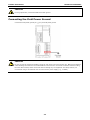
Connecting the Field Power Ground
Connect the field power ground pin ( ) to your field power ground.
CAUTION
Be sure to note the maximum possible current for each power wire and common wire. Observe all electrical
codes dictating the maximum current allowable for each wire size. If currents
exceed the maximum rating,
the wir
es will overheat, which could cause serious damage to your equipment. For safety reasons, we
recommend
using 2 mm diameter wire to connect to the power supply (e.g., 12 AWG).

ioThinx 4510 Series Hardware Installation
3-6
Mounting the Unit
In this section, we describe how to mount the device on a DIN rail and how to unmount the device from a
DIN rail.
DANGER
Never install the device while the power source is switched on
.
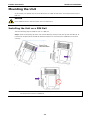
Installing the Unit on a DIN Rail
Take the following steps to install the unit on a DIN rail.
Step 1: Hook the mounting clip of the unit onto the DIN rail, and then lower the clip onto the DIN rail. At
least 55 mm of space above the DIN rail should be kept free to ensure that the installation can be done
correctly.
Step 2: Push the unit towards the DIN rail until the end of the mounting clip snaps into place.
INFORMATION
When the I/O module is inserted into the correct position, the connection between the internal bus
and the previous module is
established.

ioThinx 4510 Series Hardware Installation
3-7
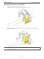
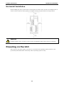
Removing the Unit from a DIN Rail
Take the following steps to remove the unit from a DIN rail.
Step 1: Use your finger to pull the release tab on the lower part of the module.
Step 2: Press the release tab (item 1 in the figure) and then remove the CPU module from the DIN rail
(item 2 in the figure).
NOTE
Disconnect all connections,
including Ethernet, serial, and power cables, from the device before removing
the device from the
DIN rail.
Page is loading ...
Page is loading ...
Page is loading ...
Page is loading ...
Page is loading ...
Page is loading ...
Page is loading ...
Page is loading ...
Page is loading ...
Page is loading ...
Page is loading ...
Page is loading ...
Page is loading ...
Page is loading ...
Page is loading ...
Page is loading ...
Page is loading ...
Page is loading ...
Page is loading ...
Page is loading ...
Page is loading ...
Page is loading ...
Page is loading ...
Page is loading ...
Page is loading ...
Page is loading ...
Page is loading ...
Page is loading ...
Page is loading ...
Page is loading ...
Page is loading ...
Page is loading ...
Page is loading ...
Page is loading ...
Page is loading ...
Page is loading ...
Page is loading ...
Page is loading ...
Page is loading ...
Page is loading ...
Page is loading ...
Page is loading ...
Page is loading ...
Page is loading ...
Page is loading ...
Page is loading ...
Page is loading ...
Page is loading ...
Page is loading ...
Page is loading ...
Page is loading ...
Page is loading ...
Page is loading ...
Page is loading ...
Page is loading ...
Page is loading ...
Page is loading ...
Page is loading ...
Page is loading ...
Page is loading ...
Page is loading ...
Page is loading ...
Page is loading ...
Page is loading ...
Page is loading ...
Page is loading ...
Page is loading ...
Page is loading ...
Page is loading ...
Page is loading ...
Page is loading ...
Page is loading ...
Page is loading ...
Page is loading ...
Page is loading ...
Page is loading ...
Page is loading ...
Page is loading ...
Page is loading ...
Page is loading ...
Page is loading ...
Page is loading ...
Page is loading ...
Page is loading ...
Page is loading ...
Page is loading ...
Page is loading ...
Page is loading ...
Page is loading ...
Page is loading ...
Page is loading ...
Page is loading ...
Page is loading ...
Page is loading ...
Page is loading ...
Page is loading ...
Page is loading ...
Page is loading ...
Page is loading ...
Page is loading ...
Page is loading ...
Page is loading ...
Page is loading ...
Page is loading ...
Page is loading ...
Page is loading ...
Page is loading ...
Page is loading ...
Page is loading ...
-
 1
1
-
 2
2
-
 3
3
-
 4
4
-
 5
5
-
 6
6
-
 7
7
-
 8
8
-
 9
9
-
 10
10
-
 11
11
-
 12
12
-
 13
13
-
 14
14
-
 15
15
-
 16
16
-
 17
17
-
 18
18
-
 19
19
-
 20
20
-
 21
21
-
 22
22
-
 23
23
-
 24
24
-
 25
25
-
 26
26
-
 27
27
-
 28
28
-
 29
29
-
 30
30
-
 31
31
-
 32
32
-
 33
33
-
 34
34
-
 35
35
-
 36
36
-
 37
37
-
 38
38
-
 39
39
-
 40
40
-
 41
41
-
 42
42
-
 43
43
-
 44
44
-
 45
45
-
 46
46
-
 47
47
-
 48
48
-
 49
49
-
 50
50
-
 51
51
-
 52
52
-
 53
53
-
 54
54
-
 55
55
-
 56
56
-
 57
57
-
 58
58
-
 59
59
-
 60
60
-
 61
61
-
 62
62
-
 63
63
-
 64
64
-
 65
65
-
 66
66
-
 67
67
-
 68
68
-
 69
69
-
 70
70
-
 71
71
-
 72
72
-
 73
73
-
 74
74
-
 75
75
-
 76
76
-
 77
77
-
 78
78
-
 79
79
-
 80
80
-
 81
81
-
 82
82
-
 83
83
-
 84
84
-
 85
85
-
 86
86
-
 87
87
-
 88
88
-
 89
89
-
 90
90
-
 91
91
-
 92
92
-
 93
93
-
 94
94
-
 95
95
-
 96
96
-
 97
97
-
 98
98
-
 99
99
-
 100
100
-
 101
101
-
 102
102
-
 103
103
-
 104
104
-
 105
105
-
 106
106
-
 107
107
-
 108
108
-
 109
109
-
 110
110
-
 111
111
-
 112
112
-
 113
113
-
 114
114
-
 115
115
-
 116
116
-
 117
117
-
 118
118
-
 119
119
-
 120
120
-
 121
121
-
 122
122
-
 123
123
-
 124
124
-
 125
125
-
 126
126
-
 127
127
-
 128
128
-
 129
129


Moxa ioThinx 4510 Series User manual
- Category
- Networking
- Type
- User manual
Ask a question and I''ll find the answer in the document
Finding information in a document is now easier with AI
Related papers
-
Moxa ioThinx 4510 Series User manual
-
-
-
Moxa ioThinx 4500 Series Modules User manual
-
-
-
-
-
-
Other documents
-
 IBA ibaPDA-Interface-MQTT Owner's manual
-
Black Box LES431A Quick start guide
-
weintek MQTT Owner's manual
-
Siemens MQTT Industrial Edge Connector Connector HurBtor V1.5 User manual
-
 STRIDE MQTT User manual
-
Alcatel-Lucent 7210 Installation guide
-
Alcatel-Lucent 7210 SAS-D Installation guide
-
ICP DAS USA MDC-211-WF Quick Start
-
-

