
INSTALLATION INSTRUCTIONS
• Level Rail ......................................... 2
• Stair Rail .......................................... 8
• Care & Maintenance, Finishing ...... 15
PORCH RAIL

2
A
B
C
D
F
H
L
G
I
E
J
K
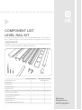
COMPONENT LIST
LEVEL RAIL KIT
Porch Rail was designed to meet the most stringent building codes. An evaluation re-
port is available through your Porch Rail Distributor or through RDI Customer Service.
COMPONENTS:
Depending on the level kit and kit length you purchased your component list will vary.
Use this as a guide to identify the individual components.
Warning:
Always wear
safety goggles.
Standard Rail Kit Wood Cover Rail Kit
A.) Wood Top Cover X Sold Separately
B.) Top Cover 1 X
C.) Top Beam 1 X
D.) Bottom Beam 1 2
E.) Beam Cover 2 2
F.) Baluster - Quantities Vary by Length-Round Iron & Glass Balusters Sold Separately
G.) Bottom Rail Support 1 1
H.) Level Mounting Bracket 4 4
I.) Screw (#12 x 5") 1 1
J.) Screw (#10 x 2") 8 8
K.) Screw (#8 x 1") 8 8
L.) Foam-Baluster Option Kits Only 2 2

3
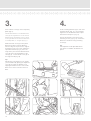
(Fig. 1)
(Fig. 3)
(Fig. 2)
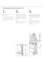
1.
Prepare all posts and mounting surfaces
before installation.
NOTE: Check with your local building
code ofce for design load requirements
for guard rails and bottom space require-
ments. All supporting structures should
be built in accordance with applicable
building codes.
2.
Establish the level placement of the
lower rail so there is no more than a
4" space from the bottom of the rail to
the standing surface. Mark the post or
mounting surface at this dimension to
determine the bottom rail height. (See
Fig. 1)
Tip:
Standard Porch Rail measures 36" in
height with a 2" space below the bottom
rail (See NOTE in Step 1).
3.
Measure the nished opening space
between surfaces where the railing is to
be installed. Transfer this measurement
to the bottom beam (D) and subtract
1/2" to allow for the mounting brackets
(Fig. 2).
Tip 1:
If all of your mounting surfaces are
plumb, transfer your measurements from
the bottom beam to the top beam (C).
Cut the beams to the measurement
(Fig. 5, 6).
Continued on next page. >>
(Fig. 4)
STANDARD LEVEL RAIL KITS

4
(Fig. 5)
(Fig. 8)
(Fig. 7)
(Fig. 11)
(Fig. 10)
(Fig. 9)
(Fig. 6)
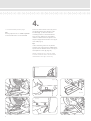
>> Continued from previous page.
Tip :
If using a power saw, a carbide tip blade
of at least 60 teeth is recommended.
4.
Place one of the beam covers (E) across
the opening where the railing is to be
installed (Fig. 7). Measure from the
mounting surface to the rst baluster
hole on each end (Fig. 8), and adjust
until these dimensions are equal. Trace
the post edge onto the beam cover (E) at
each end (Fig. 9).
Tip:
If all of mounting surfaces are plumb,
transfer your measurements and baluster
layout from the bottom beam cover (E) to
the top beam cover (E) (Fig. 10).
NOTE: A minimum of 1" from the edge
of the rst baluster hole to the end of the
routed beam cover (E) is necessary.

5
(Fig. 14)
(Fig. 15)
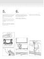
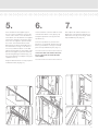
Ensure the four tabs on bracket
nest on beam as depicted.
(Fig. 13)
(Fig. 12)
(Fig. 16)
(Fig. 17)
(Fig. 18)
5.
Insert mounting brackets (H) in each end
of bottom beam (Fig. 12); ensure proper
alignment (Fig. 13). Place the bottom
beam on the marks determined in
Step 2.
Secure the brackets to the post using
mounting screws (J) (Fig. 14). Secure the
brackets to the beam using mounting
screws (K).
Tip:
You can cut wood blocks to support the
bottom beam at the proper height during
installation (Fig. 15).
6.
Cut the bottom rail support (G) to the
bottom space determined in Step 2 and
place it under the bottom beam at the
center point (Fig. 16 and 17).
Pre-drill using a 1/4" dill bit for the
bottom rail support screw (I) (Fig. 18).
Secure the bottom rail support to the
standing surface with screw provided (I).

6
(Fig. 21)
(Fig. 24)
(Fig. 23)
Ensure the four tabs on bracket
nest on beam as depicted.
(Fig. 25)
(Fig. 22)
(Fig. 20)
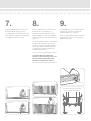
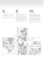
7.
Snap the bottom beam cover (E) over
the bottom beam (D) (Fig. 20, 21).
If installing glass or iron balusters, insert
foam strip (L) into baluster channel prior
to snapping on beam cover (E).
8.
Insert a baluster (F) in each hole of the
bottom beam cover (E) (Fig. 22).
Starting at one end of the rail section,
slide the top beam cover (E) (routed at
side facing down) on top of the balusters
(Fig. 23).
Insert each baluster into the correspond-
ing rout in the top beam cover (E). Let
top beam cover (E) slide down on bal-
usters, this will be used after top beam
(C) and top cover (B) installations are
complete (See Step 11).
++++++++++++++++++++++++++++++
IF INSTALLING THE WOOD TOP
COVER (A) SKIP TO PAGE 14 OF THIS
INSTALLATION GUIDE AND THEN
RETURN TO COMPLETE STEP 12.
++++++++++++++++++++++++++++++
9.
If your top beam (C) was not previously
cut (Step 3), measure your nished
opening, deduct 1/2”, and cut.
Insert mounting brackets (H) in each end
of top beam (C) (Fig. 24); ensure proper
alignment (Fig. 25).

7
(Fig. 28)
(Fig. 27)
(Fig. 26)
(Fig. 30)
(Fig. 32)
(Fig. 31)
(Fig. 29)
(Fig. 33)
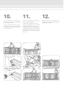
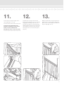
10.
Place the top beam (C), as oriented in
Fig. 25, between the posts and on top of
the balusters (Fig. 26).
Secure the brackets to the post using
mounting screws (J) (Fig. 27). Secure the
brackets to the beam using mounting
screws (K) (Fig. 28).
11.
Measure for length (Fig. 29) and cut the
top cover (B) to t (Fig. 30).
Snap the top cover (B) onto the top
beam (C) by rolling the cover to one side,
engaging the locking strip. Then, roll
the top cover (B) to the other side while
applying downward pressure. Work from
one end of the rail to the other until the
full length of the cover locks into place
(Fig. 31).
12.
Slide the top beam cover (E) up onto the
underside of the top beam (C) and snap
into place (Fig. 32, 33).

8
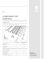
COMPONENT LIST
STAIR RAIL
Porch Rail was designed to meet the most stringent building codes. An evaluation re-
port is available through your Porch Rail Distributor or through RDI Customer Service.
Standard Rail Kit Wood Cover Rail Kit
A.) Wood Top Cover X Sold Separately
B.) Top Cover 1 X
C.) Top Beam 1 X
D.) Bottom Beam 1 2
E.) Beam Cover 2 2
F.) Baluster - Quantities Vary by Length-Round Iron & Glass Balusters Sold Separately
G.) Bottom Rail Support 1 1
H.) Stair Mounting Bracket 4 4
I.) Screw (#12 x 5") 1 1
J.) Screw (#10 x 2") 8 8
K.) Screw (#8 x 1") 8 8
L.) Foam-Baluster Option Kits Only 2 2
A
B
C
D
F
H
L
G
I
E
J
K
COMPONENTS:
Depending on the stair kit and kit length you purchased your component list will vary.
Use this as a guide to identify the individual components.
Warning:
Always wear
safety goggles.

9
(Fig. 2)
(Fig. 4)
(Fig. 3)
(Fig. 1)
(Fig. 5)
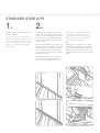
1.
Prepare all posts and mounting surfaces
before installation.
NOTE: Check with your local building
code ofce for design load requirements
for guard rails and bottom space require-
ments. All supporting structures should
be built in accordance with applicable
building codes.
2.
Temporarily secure a plank on the nose
of the stairs along side of the posts onto
which you are installing the stair rail (Fig.
1). The thickness of the plank will deter-
mine the space between the stairs and
the bottom rail.
With the white powder coated surface of
the bottom beam facing down, place the
bottom beam (D - Oriented as shown in
the Component List) on the plank (Fig.
2). Trace the angle of the posts onto the
bottom beam (Fig. 3).
Cut the bottom beam 1/2" shorter on
one end, on the angle found in Fig. 3, to
allow for mounting brackets (Fig. 4, 5).
NOTE: Depending on the angle of your
stair, code may require you to mount
the bottom beam to the tread noses (no
plank). Check with your local building of-
ce for applicable regulations.
Tip:
If both posts are plumb you can speed
your installation by placing the top beam
(C) on top of the bottom beam with the
baluster channels facing each other, and
mark both beams at once. Then cut both
beams.
STANDARD STAIR KITS

10
4.
Insert mounting brackets (H) in each end
of bottom beam (Fig. 11); ensure proper
alignment. Set the bottom beam in posi-
tion between the posts. (Fig. 12)
Secure the brackets to the post using
mounting screws (J) (Fig. 13). Secure the
brackets to the beam using mounting
screws (K).
Tip:
A wood plank can be placed between
your posts to establish the bottom rail
space.
(Fig. 7)
(Fig. 9)
(Fig. 8)
(Fig. 6)
(Fig. 10)
(Fig. 13)
(Fig. 12)
(Fig. 11)
3.
Place a beam cover (E) on the temporary
plank (Fig. 6).
NOTE: Routed holes in the bottom beam
cover (E) are angled routs. Insure that the
bottom beam with bottom cover is facing
in the right direction to allow the balusters
to stand plumb, i.e. straight up (Fig. 7).
Slide the beam cover (E) on the plank
between the posts until the distance
from the edge of the post to the edge of
the baluster rout is the same at both the
top and the bottom (Fig. 8). Trace the
angle of the post onto the bottom beam
cover (E) at the top and bottom of the
stair (Fig. 9). Cut the beam cover (E) on
the angle traced (Fig. 10).
Tip:
If both posts are plumb you can speed
your installation by placing the top beam
cover (E) on top of the bottom cover
aligning the baluster holes. Now scribe
both covers at the same time and cut
both.

11
5.
Place the bottom rail support (G) on
the nose of the tread that is nearest the
center of the section. Trace the bottom
of the beam onto the bottom rail support
and cut the support to match the angle.
Place the cut support in position under
the center of the bottom beam. Now
drill through the beam perpendicular to
the tread surface using a 3/16” bit. It is
necessary to drill the beam so the bolt
will be positioned at the front edge of the
bottom rail support to prevent the beam
from bowing during installation (Fig. 14).
Secure the bottom rail support using the
supplied screw (I).
Snap the bottom beam cover (E) in place
on bottom beam (D) (Fig. 15).
(Fig. 15)
(Fig. 18)
(Fig. 17)
(Fig. 16)
(Fig. 19)
(Fig. 14)
6.
Insert a baluster in the rst and last routs
of the bottom beam cover (E) (Fig. 16).
Snap the top beam cover (E) onto the
top beam (C).
Place the top beam (C) onto the two
balusters you installed, allowing the top
beam (C) and beam cover (E) to extend
past the top and bottom post (Fig. 17).
++++++++++++++++++++++++++++++
IF INSTALLING THE WOOD TOP COV-
ER (A), TOP AND BOTTOM BEAMS
ARE ITEM D.
++++++++++++++++++++++++++++++
7.
Now, adjust rail until the balusters are
plumb (Fig. 18). Mark the top beam (C)
and beam cover (E) on the angle at the
top and bottom post (Fig. 19).

12
(Fig. 23)
(Fig. 25)
(Fig. 24)
(Fig. 21)
(Fig. 20)
(Fig. 22)
8.
Cut the top beam (C) and cover (E) on
the angle indicated at the marks made in
Step 7. (Fig. 20)
Separate the pieces and cut the beam
1/2” shorter at the same angle. (Fig. 21)
9.
Insert a baluster in each rout of the bot-
tom beam cover (E) (Fig. 22).
Set the top beam cover (E) in place by
inserting the rst baluster (at the upper
post) in the corresponding routs of the
top beam cover (E) and work towards
the bottom. Slide the top beam cover
(E) down several inches to allow for top
beam (C) installation. (Fig. 23)
10.
Insert the mounting brackets (H) into
both ends of the top beam (C) (Fig. 24).
The top bracket will be angled down and
the bottom bracket will be angled up.
Place the top beam (C) onto the balus-
ters. Slide the beam cover (E) up to the
bottom beam to adjust the top beam (C)
to the correct angle and secure in place
using screws (J). (Fig. 25)
Secure the brackets to the beam using
screws (K).

13
(Fig. 27)
(Fig. 28)
(Fig. 26)
(Fig. 30)
(Fig. 31)
(Fig. 29)
11.
Cut the top cover (B) to length at the
stair angle (Fig. 26, 27, 28).
++++++++++++++++++++++++++++++
IF INSTALLING THE WOOD TOP
COVER (A) REFER TO STEP 3W ON
PAGE 14. ONCE COMPLETED
RETURN TO STEP 13 ON THIS PAGE.
++++++++++++++++++++++++++++++
12.
Snap the top cover (B) onto the top
beam (C) by rolling the cover to one side,
engaging the locking strip. Then, roll
the top cover (B) to the other side while
applying downward pressure. Work from
one end of the rail to the other until the
full length of the cover locks into place
(Fig. 29).
13.
Slide the top beam cover (E) up onto the
top beam (C), ensuring that it snaps into
place over its entire length and under the
top cover (B) (Fig. 30, 31).

14
1
w
.
If your top beam (D) was not previously
cut (Step 3), measure your nished
opening, deduct 1/2”, and cut.
Insert mounting brackets (H) in each end
of top beam (D) (Fig. 1); ensure proper
alignment (Fig. 2).
2
w
.
Place the top beam (D), as oriented in
Fig. 2, between the posts and on top of
the balusters (Fig. 3).
Secure the brackets to the post using
mounting screws (J) (Fig. 4). Secure the
brackets to the beam using mounting
screws (K) (Fig. 5).
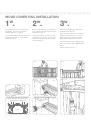
3
w
.
Measure for length (Fig. 6) and cut the
wood top cover (A) to t.
Use a 3/16” bit to drill holes through the
top beam (D) approximately every 12”
(between balusters). Holes should be
drilled down center baluster channel.
Set wood top cover (A) on top beam (D)
and secure in place with supplied screws
(Fig. 7).
Return to Step 12, page 7.
(Fig. 1)
Ensure the four tabs on bracket
nest on beam as depicted.
(Fig. 2)
(Fig. 3)
(Fig. 4)
(Fig. 5)
(Fig. 6)
(Fig. 7)
WOOD COVER RAIL INSTALLATION

15
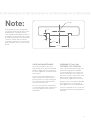
Note:
A deck board or custom wood board
may be attached to the top of the Porch
Rail Wood Kits. To properly attach, 2
slots should be routed down the base of
the board as shown below. Slots should
be made equal distance from the boards
center line. Follow steps for “Wood
Cover Rail Installation” in this instruction
guide to properly attach custom routed
board.
CARE AND MAINTENANCE
All Porch Rail products other than
textured top covers (B) are pre-nished
products. Application of any type of n-
ish to these products will void the Porch
Rail warranty.
To clean any Porch Rail product, use
mild soap and water with or without a
pressure washer on a light setting (take
care to prevent surface damage from
excessive water pressure).
Do not use any abrasive soap product
or solvent-based cleaning solutions that
may cause damage to the surface of
the product.
1/2”
1/4”
1-1/8”
2-1/4”
Center
FINISHING OF Porch Rail
TEXTURED TOP COVER (B)
Porch Rail textured top covers (B) must
be painted using a primer and paint
system designed for PVC material. The
surface must be dry, clean, and free of
dirt, grease oil, wax, soap residue, chalk
and any other foreign matter. Follow
manufacturer’s application instructions.
Railing Dynamics will not be responsible
for the performance of any primer, or
paint applied to any Porch Rail product.
It is always advisable to test a small area
for adhesion prior to proceeding with the
entire job.

RAILING DYNAMICS, INC.
FOR HOME, FOR LIFE™
135 STEELMANVILLE ROAD
EGG HARBOR TOWNSHIP, NJ 08234
TEL: (877) 420-7245
FAX: (866) 277-5160
E-MAIL: [email protected]
URL: WWW.RDIRAIL.COM
EMIPR 10.10
-
 1
1
-
 2
2
-
 3
3
-
 4
4
-
 5
5
-
 6
6
-
 7
7
-
 8
8
-
 9
9
-
 10
10
-
 11
11
-
 12
12
-
 13
13
-
 14
14
-
 15
15
-
 16
16


Ask a question and I''ll find the answer in the document
Finding information in a document is now easier with AI
Related papers
-
RDI 73018163 Operating instructions
-
RDI 73018200 Operating instructions
-
-
-
-
-
RDI 73021948 Installation guide
-
Unbranded 73019347 Installation guide
-
-
Avalon 73020654 Installation guide
Other documents
-
Swing-N-Slide Playsets 6038 Operating instructions
-
Gorilla Playsets 4431 Installation guide
-
-
WM Coffman 802428 Installation guide
-
 Crown Heritage BC4989220FB Installation guide
-
-
 Pegatha 50170001 Installation guide
-
 Veranda 73003561 Installation guide
-
Freedom 73021931 Installation guide
-


