Page is loading ...

No: 341018 – 9/12 Rev. B U.S. Patents: 5640113, 5804991
Pass & Seymour
®
High Bay • Line Voltage • Passive Infrared • Occupancy Sensor for Dry Locations
Grande hauteur • Tension secteur • Infrarouge passif • Détecteur de présence pour environnement sec
Montaje alto • Voltaje de línea • Infrarrojo pasivo • Sensor de ocupación para lugares secos
Installation Instructions • Instrucciones de Instalación • Notice d’Installation
Catalog Number(s) • Numéro(s) de Catalogue • Les Numéros de Catalogue: PSHB120277Lx
Country of Origin: Made in Taiwan • Pays d’origine: Fabriqué à Taïwan • País de origen: Hecho en Taiwán
PSHBEM
Extender
Module
Back
Box
PSHB120277
Sensor
Module
PSHBLx
Lens
or
Alignment Guides
O
P
E
N
C
L
O
S
E
Light Level
Adjustment
Trimpot
Surface
Mounting
Screw Hole
Surface
Mounting
Screw Hole
DIP Switches
PIR Sensor
(do not touch)
Detection
Indicator LED
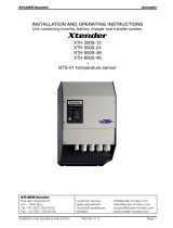
DESCRIPTION AND OPERATION
The PSHB120277Lx occupancy sensors are designed for automatic lighting control in warehouse high bay dry
location applications. All models contain a passive infrared sensor (PIR). The PSHB120277Lx series sensors are
modular and are made up of a Power Module and a Lens. The coverage area is determined by the lens module.
There are three different lenses available. See the Coverage section for more information.
All models in the PSHB120277Lx series use a set of DIP switches to set the time delay and PIR sensitivity, as
explained below.
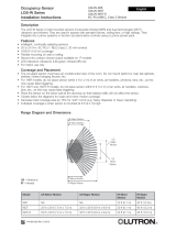
COVERAGE
Coverage patterns, density and range, are determined by the type of Lens attached to the PSHB120277Lx.
PSHB120277L1
The L1 Lens offers linear patterns best suited for high bay aisleway applications. The Fresnel lens is designed to
detect walking motion when mounted at or around 40’. In optimal conditions, the lens has a 60’ linear detection
range.
PSHB120277L2
The L2 Lens offers 360° coverage and is best suited for open area and aisleway coverage in high bay applications.
The L2 is a multi-cell, multi-tier Fresnel lens offering a high density coverage pattern that spreads over a 40’
diameter area at a height of 20’.
PSHB120277L3
Similar to the L2 Lens, the L3 offers 360° coverage, and is best suited for open areas and aisleways in high bay
applications. The L3 is a multi-cell, multi-tier Fresnel lens offering a high density coverage pattern.The L3
is designed for mounting at heights between 30’ to 40’, with a coverage area up to 60’ in diameter when mounted
at 40’.
INSTALLATION
CAUTION
Turn the power off at the circuit breaker before installing the sensor.
1. Determine the mounting location appropriate to the features of the power module and the coverage area. Careful
consideration must be given to sensor placement. Avoid placing the sensor where the edge of the xture,
shelving or other obstructions may block the sensor’s line of sight. Mount the sensor below the edge of the xture
and away from the uorescent lamps so that the heat from the lamps does not affect the sensor.
2. Make sure that you have the appropriate accessories for the sensor mounting conguration. (See Mounting
Options.)
3. Assemble any necessary mounting accessories and attach them to the power module, making sure that the
ying leads from the power module are accessible.
4. Connect the line voltage and load wires to the sensor leads as shown in the Wiring Diagram for the unit’s
application.
• Do not allow bare wire to show.
• Make sure all connections are secure.
5. Restore power from the circuit breaker.
WIRING
MOUNTING OPTIONS
The PSHB120277Lx can be attached to the xture or junction box using the back box and chase nipple or directly
to the xture surface via the two screw holes provided in the Power Module (see Surface mounting below). The
Extender Module (PSHBEM) allows attaching the sensor to the side of the xture in a number of congurations
using provided chase nipples.
Back box mounting requires a standard 1/2” knockout for the chase nipple. The Power Module mounts to the back
box with a bayonet type tting requiring a slight twist of the units to separate them or lock them into place. The box
comes ready for side mounting. It can be modied for rear mounting as follows:
1. Pop out the cap in the rear knockout.
2. Un-snap the chase nipple from the side mount and snap into the rear mounting hole.
3. Use the cap to close the side mount hole.
4. The chase nipple provided can be pushed into a standard 1/2” knockout in a metal xture [max of 1 mm (0.04”)
thick metal] without the need for the included internal nut. The nut can be used for added security if necessary.
The PSHBEM extender module allows threading the wires through its chase nipples and into the xture for
connection. The two sides of the PSHBEM are then snapped together to protect the wires. The short chase nipple
is designed to snap into the PSHBEM connection box while the longer chase nipple snaps into any metal xture or
connection box with a standard knockout. The caps on the PSHBEM can be removed in various congurations to
allow moving the chase nipples and adjusting the height of the sensor on the xture.
Using the back box and PSHBEM Extender Module
Surface mounting requires holes in the xture to pass wires
and attach two #6-32 screws through the surface mounting
screw holes on the component side of the Power Module as shown.
ADJUSTMENTS
Sensor factory pre-sets are as follows (default settings are bold):
Factory Switch Settings
1 2 3 4 5 6 7 8 9 10
ON OFF OFF OFF OFF ON ON OFF OFF OFF
PIR Sensitivity (switches 1 & 2) ....................... Medium 85%
Time Delay (switches 3-7) ............................... 15 Minutes
Overrides (switches 8-10) ............................... See table below for each model.
N/A = not applicable, no effect.
PIR Sensitivity (Switches 1-2)
The factory setting of 85% is suitable for most applications, but it may be necessary to adjust the PIR sensitivity
if there is any environmental interference causing false triggers or if sensitivity needs to be increased for your
particular application. Use DIP switches 1 & 2 to adjust sensitivity.
Switch 1 2 PIR SENSITIVITY
OFF OFF 100% (HIGH)
ON OFF 85% (NORMAL)
OFF ON 75% (MEDIUM )
ON ON 60% (LOW)
Time Delay (Switches 3-7)
Use DIP switches 3 to 7 to adjust the time delay.
Switch 3 4 5 6 7 TIME DELAY
ON ON ON ON ON 15 seconds
OFF ON ON ON ON 5 minutes
OFF OFF ON ON ON 10 minutes
OFF OFF OFF ON ON 15 minutes
OFF OFF OFF OFF ON 20 minutes
OFF OFF OFF OFF OFF 30 minutes
PIR Override (Switches 8-10)
Overrides can disable control features of the PSHB120277Lx power module. The table below describes the override
functions of each PSHB120277Lx model.
IMPORTANT START-UP INFORMATION
A 60-second start-up period occurs during initial installation and after a power failure of 5 minutes or more. After
applying power to the sensor wait at least 60 seconds for the sensor to begin detecting occupancy and the load to
turn ON. It may turn ON during the start-up period, depending on the state of the relay when power was off.
• If the sensor detects occupancy during the start-up, when the load turns ON it stays ON as long as the sensor
continues to detect motion, plus the Time Delay.
• If no occupancy is detected during the 60-second start-up, the load may come on anyway during the start-up.
If no occupancy is detected by the time the start-up is complete, the relay opens and the load turns OFF.
MODEL/SWITCH # 8 9 10 FUNCTIONALITY LOAD EFFECT
PSHB120277Lx
PIR sensor, 1 load relay
OFF N/A N/A Occupancy control enabled Controlled by Occupancy
ON N/A N/A Override PIR Load always ON
TROUBLESHOOTING
If you suspect improper operation, review the Start-Up information. After start-up, the sensor will open or close the
relay to correspond to the occupancy status of the area. When power to the sensor is lost, the relay(s) close, turning
on the load if the load still has power.
To quickly test the unit, set the time delay to minimum. Wait for the start-up period to end. Move out of the sensor’s
view. Lights should turn OFF after 15 seconds. Move into the sensor’s view. The sensor’s Red LED should blink and
the lights should turn ON.
Red LED on power module does not blink:
Check sensor wire connections. Verify the neutral wire is tightly secured.
Red LED blinks but lights do not turn ON:
1. Make sure that power to the sensor has been ON continuously for at least one minute, then
a) Turn OFF power to the sensor.
b) The relay(s) will close.
c) Turn ON power to the sensor.
d) The load should come ON. If not, continue with step 2.
2. Check power connections to the light xture.
3. Check all sensor wire connections. Verify the load wire is tightly secured.
CAUTION
Turn power off at the circuit breaker before installing
sensor.
AVERTISSEMENT
Coupez l’alimentation du disjoncteur avant
d’installer le détecteur.
PRECAUCIÓN
Desconecte la alimentación del disyuntor antes de
instalar el sensor.
SPECIFICATIONS
Voltages .............................................120/277VAC, 60Hz
Load Requirements
@ 120VAC, 60Hz ...........0-800W ballast or tungsten
@ 277VAC, 60Hz ............................0-1200W ballast
@ 120VAC .......................................................1/6 hp
LENS
Hallway L1 ........ 40 ft. mounting height, 60 ft. x 20 ft.
L2 ..................20 ft. mounting height, 40 ft. diameter
L3 ..................40 ft. mounting height, 60 ft. diameter
SPÉCIFICATIONS
Voltages ......................................... 120/277 V c.a., 60 Hz
Conditions de charge
à 120 V c.a., 60 Hz ........0-800 W ballast ou tungstène
à 277 V c.a., 60 Hz ........................... 0-1200 W Ballast
à 120 V c.a. .........................................................1/6 hp
LENTILLE
L1 pour couloir ....... Hauteur de montage de 12,19 m,
18,28 m x 6,09 m.
L2 ............................. Hauteur de montage de 6,09 m,
diamètre de 12,19 m.
L3 ...........................Hauteur de montage de 12,19 m,
diamètre de 18,28 m.
ESPECIFICACIONES
Voltajes ...........................................120/277 V CA, 60 Hz
Requerimientos de carga
A 120 V CA, 60 Hz .......0 a 800 W balasto o tungsteno
A 277 V CA, 60 Hz ...................... Balasto de 0-1200 W
A 120 V CA..........................................................1/6 hp
LENTE
Hallway L1 ...... Altura de montaje de 12 m (40 pies),
18 m x 6 m (60 pies x 20 pies)
L2 ..................... Altura de montaje de 6 m (20 pies),
diámetro de 12 m (40 pies)
L3 ................... Altura de montaje de 12 m (40 pies),
diámetro de 18 m (60 pies)
PSHB120277L2
PSHB120277L1
PSHB120277L3
Ceiling
30 20 10 0102
03
0
0
10
20
30
40
Coverage Side View
40 30 20 10 010203040
0
20
10
10
20
20 ft
Coverage Top View
Ceiling Side View
Top View L1
03612273436122734 20 20
0
10
20
30
40
Coverage Side View
036 12 27 3436122734
20
20
0
3
6
3
6
12
27
34
12
27
34
20
20
68 ft
Coverage Top View
0663 3
Ceiling
Side View Top View L3
039636912 12
10
20
0
15
Ceiling
Coverage Side View
5
151820 15 18 20
Coverage Top View
20 10 01020
0
20
10
10
20
40 ft
Ceiling Side View
Top View L2
120/277VAC Wiring
Hot
Neutral
Load
Black
White
Red
PSHB120277Lx
/