Page is loading ...

FAIRCHILD MODEL 64
PNEUMATIC SERVICE REGULATOR
Installation, Operation and Maintenance Instructions
1.29
32.6
1.91 KNOB
48.5
3.15
INLET/OUTLET PORT SPACING
80
6.36
MAX KNOB
161.5
2.98
75.7
2.25
MOUNTING HOLES BACK SIDE
57.2
1.25 MOUNTING
31.8
0.32
THR
U
2 MOUNTING HOLE
S
8.1
INLET/OUTLET
1/4 NPT,
[1/4 BSPT] OR
[1/4 BSPP]
(2) MOUNTING HOLES
1/4-20 UNC-2B X 0.38 DP
[M6-1 X 9.5 DP]
BACK SIDE
EXHAUST
1/4 NPT
[1/4 BSPT]
INLET
OUTLET
EXHAUST
0.31
SCREW
7.9
6.00
MAX SCREW
152.4
6.66
TAMPERPROOF
169.2
2.71
68.9
0.71
18
0.24
6
2.14
54.4
(2) GAGE
PORTS
1/4 NPT
[1/4 BSPT] OR
[1/4 BSPP]
0.75
HEX TAMPERPROOF
19.1
[MM]
INCH
1.74
44.1
3.02
76.8
0.25
6.4
0.75
HEX
19.1
0.50 HEX
12.7
2.25
OPTION P
57.2
2.88
OPTION P
73
OPTION P2
1/4-20 UNC-2B
THRU TYP 2
P OPTION
PANEL MOUNTING
OPTION P
1/2-20 UNF-2A
2.92
GAGE PORT
74.2
1.52
38.7
GAGE
OPTION
2"
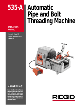
Use the two 23/64 thru holes in the Body to mount
the Model 64. The Model 64 may be mounted in
any orientation.
Clean all pipelines to remove dirt and scale before
installation.
Apply a minimum amount of pipe compound to the
male threads of the tting only. Do Not use teon
tape as a sealant. Start with the third thread back and
work away from the end of the tting to avoid contami-
nating the regulator. Install the regulator in the air line.
The Inlet and Outlet ports are labeled “In” and “Out”.
Tighten all connections securely. Avoid undersized
ttings that limit the ow through the regulator. For
more information, see Figure 1.
NOTE:
The Model 64 has an Adjustment Screw that con-
trols output pressure. To increase pressure, turn
the Adjustment Screw clockwise. To decrease
pressure, turn the Adjustment Screw counterclock-
wise. For more information, see Figure 1.
Oil free air must be applied to the regu-
lator. If an air line lubricator is used, it
MUST be located downstream of the
regulator to avoid interference with per-
formance.
OPERATION
INSTALLATION
Figure 1. Model 64 Outline Dimensions

IS-10000064
Litho in USA
Rev. 03/08
MAINTENANCE
Figure 2. Model 64
If the standard maintenance procedure
does not correct the problem, install the
service kit.
Troubleshooting
Source
Problem
• If contaminated,
clean the
source.
Solution
High
Bleed
Leakage
Tighten the
Body Screw.
• Relief Pintle
• Relief Seat
Body Screw
NOTE:
Service Kit
Difcult to
Adjust
• Adjustment Screw
• Lubricate the
Adjustment
Screw threads
and end.
NOTE:
The presence of some diester oils in the air
lines can accelerate elastomer deteriora-
tion and decrease the life span of this unit.
EA-19968-1
Vent
Inlet
Valve
Body
Adjusting
Knob
Bonnet
Outlet
Gage
Port
/