
CNC
8037 ·T·
New features
Ref. 2001
Soft: V02.4x

This product uses the following source code, subject to the terms of the GPL license. The applications busybox V0.60.2;
dosfstools V2.9; linux-ftpd V0.17; ppp V2.4.0; utelnet V0.1.1. The librarygrx V2.4.4. The linux kernel V2.4.4. The linux boot
ppcboot V1.1.3. If you would like to have a CD copy of this source code sent to you, send 10 Euros to Fagor Automation
for shipping and handling.
All rights reserved. No part of this documentation may be transmitted,
transcribed, stored in a backup device or translated into another language
without Fagor Automation’s consent. Unauthorized copying or distributing of this
software is prohibited.
The information described in this manual may be changed due to technical
modifications. Fagor Automation reserves the right to make any changes to the
contents of this manual without prior notice.
All the trade marks appearing in the manual belong to the corresponding owners.
The use of these marks by third parties for their own purpose could violate the
rights of the owners.
It is possible that CNC can execute more functions than those described in its
associated documentation; however, Fagor Automation does not guarantee the
validity of those applications. Therefore, except under the express permission
from Fagor Automation, any CNC application that is not described in the
documentation must be considered as "impossible". In any case, Fagor
Automation shall not be held responsible for any personal injuries or physical
damage caused or suffered by the CNC if it is used in any way other than as
explained in the related documentation.
The content of this manual and its validity for the product described here has been
verified. Even so, involuntary errors are possible, thus no absolute match is
guaranteed. Anyway, the contents of the manual is periodically checked making
and including the necessary corrections in a future edition. We appreciate your
suggestions for improvement.
The examples described in this manual are for learning purposes. Before using
them in industrial applications, they must be properly adapted making sure that
the safety regulations are fully met.

New features
CNC 8037
·3·
INDEX
VERSION V02.31
1. Synchronization of the axes movement with the feed hold ................................................................................ 5
2. Set the machine coordinate (G174) ................................................................................................................... 6
3. Anticipation of M functions ................................................................................................................................. 7
4. Save screen by pressing [SHIFT] + [Page Up] .................................................................................................. 8
5. Working with two additive handwheels simultaneously...................................................................................... 9
6. CNC8055 (client) and PC (server) connection ................................................................................................. 11
7. Expansion of zero offsets to 40........................................................................................................................ 12
8. General machine parameter CODEPAGE (P197) ........................................................................................... 12
9. Anticipated spindle stop ................................................................................................................................... 13
10. Deletion of temporary files on the hard disk................................................................................................... 13
11. PANDRAW variable for grinding cycles ......................................................................................................... 14
VERSION V02.33
1. Different accelerations for G00 and G01.......................................................................................................... 15
2. Select handwheel movements in radii or diameters, when the axis is in diameters ........................................ 16
3. Calibrating bits or mills with a live tool using the F10 form factor .................................................................... 17
4. CNCDISSTAT variable..................................................................................................................................... 17
VERSION V02.40
1. New way of drawing the tool path .................................................................................................................... 19
2. Execution of a part-program from a USB hard drive ........................................................................................ 19
3. Executing a part-program from the remote hard drive ..................................................................................... 21
4. Reset X, Y, and Z axes before executing a program ....................................................................................... 22
5. A new way to continue executing an interrupted program ............................................................................... 23
6. Parameter M in instruction G51 ....................................................................................................................... 24
7. New variable PRGTXT..................................................................................................................................... 24
8. CNC communication using a device via the CANopen bus ............................................................................. 25
9. PANDRAW variable value to identify the PCALL screen ................................................................................. 25
10. Tapping cycles (levels 4 and 5) on the CNC8037 TC model ......................................................................... 26
10.1. Geometry definition............................................................................................................................... 27
10.2. Basic operation. Thread repair ............................................................................................................. 33
11. BCSD drives with a 23 bit encoder ................................................................................................................ 34
12. New variables for progress and remaining machining time ........................................................................... 34
13. Multiple slot milling cycle 2 (level 6) ............................................................................................................... 35

·4·
New features
CNC 8037

New features
CNC 8037
·T· MODEL
SOFT: V02.3X
·5·
VERSION V02.31
1 Synchronization of the axes movement with the feed hold
Its use is recommended with punching presses so that the delay that occurs between the time when
the feed hold signal raises and the axes begin to move is always the same.
Synchronization activation
To activate synchronization, set bit 2 of the general machine parameter IPOTIME (P73)=1.
IPOTIME (P73)
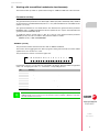
This parameter has 16 bits counted from right to left.
Each bit has a function or work mode associated with it. By default, all the bits will be assigned the
value of ·0·. Assigning the value of ·1· activates the corresponding function.
Bit Meaning Bit Meaning
0 8
1 9
2 Activates the synchronization of the
axes with the feed hold.
10
3 11
4 12
5 13
6 14
7 15
Default value in all the bits: 0
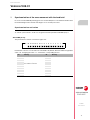
bit
15
14 13 12 11 10 9 8 7 6 5 4 3 2 1 0

·6·
New features
CNC 8037
·T· MODEL
SOFT: V02.3X
2 Set the machine coordinate (G174)
Function G174 may be used to set the machine coordinate of an axis; in other words, temporarily
set a new machine zero. The new machine zero remains active until the axis is homed; the CNC
then restores the original machine reference zero (set in the machine parameters).
After executing function G174, the CNC assumes that the programmed coordinate defines the
current position referred to machine reference zero (home). The zero offsets, movements with
respect to machine zero, etc. will be referred to the coordinate programmed in G174.
Programming the function
Program function G174, and then the machine coordinate of a single axis. With this function, only
the machine coordinate of an axis may be set; to set the machine coordinates of several, program
one G174 for each one of them.
When it comes time to setting the machine coordinate, the CNC uses the predefined unit system
in the control. If it is a linear axis, use millimeters or inches, as defined in general machine parameter
INCHES (P8). If it is a rotational axis, use degrees. The CNC ignores all the other options,
radius/diameter, mirror image, scaling factor, etc.
The active zero offsets before G174 remain active and now refer to the new machine coordinate.
Programming format:
The programming format is as follows:
G174 X..C
X..C Machine coordinate of the indicated axis.
Example:
G174 X100
Considerations and limitations
By itself, function G174 does not cause any axis movement. After executing function G174, the CNC
considers that the axis is homed and verifies that it is within the software travel limits.
The normal use of this function is on rotational axes without limits, which always turn in the same
direction.
The CNC does not allow setting the machine coordinate on slaved axes, grantry, tandem or on axes
that are part of the active kinematics or active transform. It is also not permitted to set he machine
coordinate on the C axis of the lathe or on axes with encoded I/Os. Before setting the new machine
coordinate, the CNC checks that the axis is in position and it is not synchronized; if this is not the
case, it issues an error message.
When executing G174, if there is any active coordinate transformation (G47, G48, G49, etc.), the
CNC will issue an error.
It is possible to use the function G174 from the PLC channel and from the user channel.
Properties of the function and Influence of the reset, turning the CNC
off and of the M30 function
Function G174 is modal. The new machine zero is unaffected by either function M02 or M30, or by
a reset, an emergency or by shutdown of the CNC. On power-up, the CNC assumes the machine
coordinates that were active when the CNC was turned off.

New features
CNC 8037
·T· MODEL
SOFT: V02.3X
·7·
3 Anticipation of M functions
The M functions anticipation feature may be used to transfer an M function to the PLC before the
previous movement ends. This feature is very useful in punching presses. In these machines, it
allows the next punching to be prepared from the PLC before the previous movement ends.
Definition of the M functions to be executed in advance
The table of auxiliary M functions has an 8-bit field for customization.
To define the M functions that will be executed in advance, use bit 5 of the desired M functions
customization. The time by which these M functions are anticipated is indicated in the general
machine parameter MANTIME (P196).
Customization bit 5 from the M auxiliary function table
Indicates whether the M auxiliary function is executed in advance.
MANTIME (P196)
General machine parameter that indicates the time in milliseconds by which the M auxiliary functions
are anticipated that are indicated by means of customization bit 5 from the M auxiliary functions table.
Considerations and limitations
M functions can be anticipated in G5, G7 and G50, but they cannot be anticipated in G51.
Only those M auxiliary functions are anticipated that are executed from the main channel. The M
functions that are executed from the PLC channel are not anticipated.
Only those M auxiliary functions are anticipated that do not have a predefined meaning for the CNC.
The following M functions are not anticipated:
M0, M1, M2, M3, M4, M5, M6, M8, M9, M19, M30, M41, M42, M43, M44 and M45.
An M auxiliary function is only anticipated if there are no other low level blocks (F, G, etc.) between
the previous movement block and the M function block.
The M functions that are anticipated must be programmed individually in the block; they cannot be
programmed together with other M, S or T functions. Otherwise, the CNC will display the error: "The
M function must be programmed by itself in the block".
The M functions that are anticipated may be programmed in the movement blocks. If the M function
is customized to be executed after the movement block, the combination (movement - punching M)
may be programmed in the same block.
The anticipation of the M functions only occurs in execution mode. M functions are not anticipated
in any of the simulation modes.
Value Meaning
0 The M auxiliary function is not executed in advance.
1 The M auxiliary function is executed in advance.
Possible values
Integers between 0 and 65535 ms.
Default value: 0 (not executed in advance)
If there are filters with set parameters on the axes, the anticipation time is greater than that indicated
in the general machine parameter MANTIME (P196). In this case, in order to ensure the correct
functioning of the feature, it will be necessary to set this parameter.

·8·
New features
CNC 8037
·T· MODEL
SOFT: V02.3X
4 Save screen by pressing [SHIFT] + [Page Up]
When the key sequence [SHIFT] + [Page Up] is pressed, an image of the currently active screen
will be saved in the CNC.
If a USB memory drive (Pendrive) is connected when the screen is saved, the image will be saved
in the <PAN> directory of said memory. If the <PAN> directory does not exist on the USB memory
drive, it will be created automatically.
If there is no USB memory drive (Pendrive) connected when the screen is saved, the image will be
saved in the <PAN> directory of the hard disk (KeyCF) of the CNC.
The saved image can be sent by DNC or FTP.
Image format:
The image format will be ".bmp" and the name of the saved file will be the following:
S month day hour minute second.bmp (no spaces in the file name).
Example of a saved screen:
Name of a screen saved on October 30, 2015 at 9:32 and 50 seconds:
S1030093250.bmp

New features
CNC 8037
·T· MODEL
SOFT: V02.3X
·9·
5 Working with two additive handwheels simultaneously
This feature makes it possible to operate while moving two additive handwheels at the same time.
Parameter setting
The general machine parameters from AXIS1 (P0) to AXIS7 (P8) and from AXIS9 (P136) to AXIS12
(P142) must have a handwheel defined (value of 11 or 12) and a handwheel associated with an axis
(values of 21 to 29).
The general handwheel is associated with the axis defined in the general machine parameter
MPGAXIS (P76). In additive handwheel mode, the flywheel moves only the axis indicated in the
general parameter MPGAXIS (P76).
To enable this feature, assign value 1 to bits 10, 11 and 15 of the general machine parameter
ADIMPG (P176). The value of all bits in this parameter will be as follows:
ADIMPG (P176) = 1000 1100 0000 0000.
ADIMPG (P176)
This parameter enables manual intervention with an additive handwheel.
This function allows jogging the axes while a program is being executed. This movement will be
applied as if it were another zero offset.
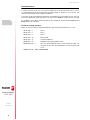
This parameter has 16 bits counted from right to left.
Each bit has a function or work mode associated with it. By default, all the bits will be assigned the
value of ·0·. Assigning the value of ·1· activates the corresponding function.
Bit Meaning
0 - 9 Not used.
10 Working with two additive handweels simultaneously.
11 Selecting the additive handwheel as handwheel associated with the axis
12 The resolution of the handwheel is set by g.m.p. ADIMPRES.
13 Manual intervention enabled with look-ahead.
14 Cancel the additive offset after M02, M30, emergency or Reset.
15 Manual intervention with additive handwheel is available.
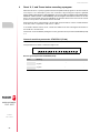
Default value in all the bits: 0
bit
15
14 13 12 11 10 9 8 7 6 5 4 3 2 1 0
As of this version, in order for the CNC to accept a new value for the general machine parameter
ADIMPG (P176), it is necessary to press the keystroke sequence [SHIFT] + [RESET] or shut down
the CNC and then turn it back on.
i

·10·
New features
CNC 8037
·T· MODEL
SOFT: V02.3X
Considerations
In JOG movement mode, the only active handwheel is that indicated with value 11 in its
corresponding parameter (general machine parameters AXIS1 to AXIS12). To move an axis, first
select the axis and then move it with the handwheel.
In automatic mode, the handweels will behave as handwheels associated with an axis. The user
may move 2 handweels at the same time. To do this, the PLC MANINT* marks must be activated.
For example, to move the X and Z axes with the two handweels, the PLC marks MANINTX and
MANINTZ must be activated.
Parameter setting example:
Define an electronic and mechanical handwheel in general machine parameters P1 to P8.
AXIS1 (P0) = 1 Axis X.
AXIS2 (P1) = 2 Axis Y.
AXIS3 (P2) = 3 Axis Z.
AXIS4 (P3) = 10 Main spindle.
AXIS5 (P4) = 11 General handwheel.
AXIS6 (P5) = 23 Handwheel associated with the Z axis.
MPGAXIS (P76) = 1 Associate the handwheel with the Z axis. When the CNC is in
automatic mode, when the handwheel is moved, the Z axis will
move.
ADIMPG (P176) = 1000 1100 0000 0000

New features
CNC 8037
·T· MODEL
SOFT: V02.3X
·11·
6 CNC8055 (client) and PC (server) connection
In addition to a local hard disk (on the CNC itself), the CNC can also have a remote hard disk
accessible through Ethernet. The CIFS protocol is used to communicate with the remote hard disk.
As remote hard disk, it is possible to use the hard disk of a PC or just a folder. The PC that makes
its hard disk (server) public must be connected to the local network.
Once communication has been established, the directory of the connected PC will appear in the
CNC browser with the name "REMOTE DISK".
The interface and the softkeys of the CNC will the same as if it were a local hard disk. The CNC
directories cannot be seen from the PC.
Ethernet parameters
The following Ethernet parameters are available to configure communications via this protocol:
USER (P3)
Name of the user for connection to the CNC on the PC. If the parameter is not set, indicate that there
is no user.
DOMAIN (P4)
Windows network domain. If the parameter is not set, indicate that there is no domain.
PASSWORD (P5)
User password for connection to the CNC on the PC. If the parameter is not set, indicate that there
is no password.
IPSNFS (P28)
IP address of the server acting as remote hard disk. If other than 0, the remote hard disk is activated.
DIRNFS (P29)
Directory of the server that is used as remote hard disk.
NFSPROTO (P32)
To activate the CIFS communication protocol, set value as 2.
Possible values
Four numbers between 0 and 255 separated by dots.
Default value: 0.0.0.0 (there is no remote hard disk)
Possible values
It admits up to a maximum of 22 characters (without blank spaces).
Default value: Nameless

·12·
New features
CNC 8037
·T· MODEL
SOFT: V02.3X
7 Expansion of zero offsets to 40.
G159 N1 to N40. Absolute zero offsets.
To apply any zero offset defined in the table.
The first six zero offsets are the same as programming G54 through G59, except that the values
of G58 and G59 are absolute. This is because function G159 cancels functions G54 through G57
and, consequently, there is no active zero offset to add the G58 or G59 to.
8 General machine parameter CODEPAGE (P197)
General machine parameter that enables extended ASCII characters to be displayed. This makes
it possible to display those characters in the comments of the part programs, regardless of the
language in which the CNC is configured through the general machine parameter LANGUAGE
(P122).
To display extended ASCII characters, a value other than 9 must be assigned in this general
parameter.
Furthermore, if this parameter is configured with a value of 9, an error will not be returned when
executing a part program that contains extended ASCII characters in mainland Chinese.
CODEPAGE (P197)
Define the language in which to display the extended ASCII characters in the CNC.
Value Meaning
0..9 Permits the display of extended ASCII characters.
9 An error is not returned when executing a part program with extended ASCII characters
in mainland Chinese.
10..12 Permits the display of extended ASCII characters.
Default value: 9

New features
CNC 8037
·T· MODEL
SOFT: V02.3X
·13·
9 Anticipated spindle stop
This feature permits moving up the spindle stop order. This is useful in laser cutting machines, in
which the analog setpoint output of the spindle is used to regulate the laser power and it is necessary
for the final movement to coincide with the time when the spindle stops (S=0).
SANTIME
CNC variable that permits the time, in milliseconds, to be programmed that the start of the spindle
deceleration is anticipated before the end of the movement. This variable can be read and written
from the CNC and the PLC, but only read from the DNC.
The variable SANTIME does not stop block preparation.
During the execution of a program, if a movement block is followed by an S0 block and the variable
SANTIME has a value other than 0, the spindle stop order is advanced. The time of the anticipation
will be that indicated in milliseconds in the SANTIME variable.
This variable will only be taken into account if G5 is active. In the rest of the cases, the spindle stop
will not be advanced.
10 Deletion of temporary files on the hard disk
The new softkey [CLEAN DISK] makes it possible to delete the temporary files that have been
created on the hard disk. To access this softkey, go to: DIAGNOSIS / TESTING / HARD DISK.
Example of files that are deleted when the softkey [CLEAN DISK] is pressed:
• Screens saved with [SHIFT] + [Page Up].
• Files with drive variables.
If an anticipation of the spindle stop is programmed and there are active filters, the anticipation will
be greater than that defined in the SANTIME variable. In this case, the anticipation must be adjusted.
i

·14·
New features
CNC 8037
·T· MODEL
SOFT: V02.3X
11 PANDRAW variable for grinding cycles
WINDRAW55 application. Number of the screen created by the user or the manufacturer and is
being consulted.
Even if ESC is pressed (and then START is pressed and the cycle is executed) and the focus
changes, the screen number remains.

New features
CNC 8037
·T· MODEL
SOFT: V02.3X
·15·
VERSION V02.33
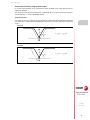
1 Different accelerations for G00 and G01
The movements programmed using G00 (rapid feedrate) are executed using the rapid feedrate
found in the axis machine parameter "G00FEED".
Two new axis parameters are available to define the acceleration and jerk used for the movements
in G00 on each axis: ACCTIMG0 (P105) and JERKLIG0 (P106).
If the value of these two parameters equals 0, the CNC will operate in both G00 and G01, using
the values of the axis parameters ACCTIME (P18) and JERKLIM (P67). In this manner, the G00
and G01 acceleration and jerk will be the same.
To achieve a different axis acceleration during the G00 operation, change the axis parameter value
ACCTIMG0 (P105) to the desired value.
To achieve a different axis jerk during the G00 operation, change the axis parameter value
JERKLIG0 (P106) to the desired value.
Axis machine parameters
ACCTIMG0 (P105)
Defines the acceleration stage or the time it takes the axis to reach the feedrate selected with axis
parameter GOFFED (P38) when performing G00 movements. This time is also valid for the
deceleration stage.
If the ACCTIMG0 (P105) and JERKLIG0 (P106) values equal 0, when performing a G00 movement,
the acceleration will be that indicated for the axis machine parameter ACCTIME (P18).
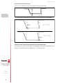
JERKLIG0 (P106)
Defines the acceleration derivative for the G00 movements. It may be used to limit the acceleration
changes to smooth the machine movements on small speed increments or decrements and with
FFGAIN values close to 100%.
The CNC ignores this parameter when moving with electronic handwheels, mechanical handwheels,
look ahead, threading (G33) and rigid tapping. If the ACCTIMG0 (P105) and JERKLIG0 (P106) values
equal 0, when performing a G00 movement, the jerk will be that indicated for the axis machine
parameter JERKLIM (P67).
The smaller the value assigned to JERKLIG0, the smoother the machine’s response, but the acc/dec
time will be longer.
Recommended values:
In millimeters JERKLIG0 = 82*G00FEED / ACCTIMG0**2
In inches JERKLIG0 = 2082*G00FEED / ACCTIMG0**2
If the stability of the machine is affected by the values mentioned earlier, the JERKLIG0 value should
be lowered to half as much.
Possible values
Integers between 0 and 65535 ms.
Default value: 0
Possible values
Between 0 and 99999.9999 m/s
3
.
Default value: 0

·16·
New features
CNC 8037
·T· MODEL
SOFT: V02.3X
2 Select handwheel movements in radii or diameters, when the axis is
in diameters
The bit 13 of the general machine parameter HDIFFBAC (P129) selects whether the handwheel
movements and incremental jog are made using radii or diameters, when the axis coordinates are
displayed in diameters.
HDIFFBAC (P129)
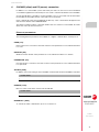
This parameter has 16 bits counted from right to left.
Each bit has a function or work mode associated with it. By default, all the bits will be assigned the
value of ·0·. Assigning the value of ·1· activates the corresponding function.
Bit 13:
The bit 13 indicates whether the handwheel movements and incremental jog are made using radii
or diameters, when the axis coordinates are displayed in diameters.
(0) The movements are performed using radii.
(1) The movements are performed using diameters.
Bit Meaning Bit Meaning
0 Handwheel ·1· 8
1 Handwheel ·2· 9
2 Handwheel ·3· 10
3 Handwheel ·4· 11
4 12
5 13 The movement of the axis using the handwheel
will be performed in diameters.
6 14 Axis filters for movements with the handwheel.
7 15 It limits the movement.
Default value in all the bits: 0
bit
15
14 13 12 11 10 9 8 7 6 5 4 3 2 1 0

New features
CNC 8037
·T· MODEL
SOFT: V02.3X
·17·
3 Calibrating bits or mills with a live tool using the F10 form factor
For this version and later versions, the probe tool calibration (level 2) allows for the calibration of
live tool bits and mills using the F10 form factor.
The operation of the calibration cycle of a live tool is the same as that for a non-live tool.
This calibration level requires the purchase of the right software options purchased and the use of
a table-top probe.
4 CNCDISSTAT variable
The new variable CNCDISSTAT indicates the status of the CNC to execute a program.
• If the variable CNCDISSTAT is set to 0, program execution is permitted.
• If the variable CNCDSSTAT is set to a value other than 0, program execution is not permitted.
The manufacturer's PLC program may read this variable using the instruction CNCRD, so as to
determine the CNC status.

·18·
New features
CNC 8037
·T· MODEL
SOFT: V02.3X

New features
CNC 8037
·T· MODEL
SOFT: V02.4X
·19·
VERSION V02.40
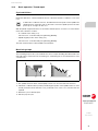
1 New way of drawing the tool path
There a new way of drawing the tool path which does not show all the calculated points. This way
of drawing the tool path means that it is faster, however, since it does not display all the calculated
points then it is less precise.
To draw the tool path using all the calculated points, set the general machine parameter as
FLWEDIFA (P132) to 1.
General machine parameter FLWEDIFA (P132)
Indicating the way in which the tool path is drawn.
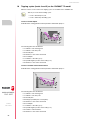
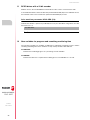
2 Execution of a part-program from a USB hard drive
The CNC supports the connection of a "Pen Drive" memory device. These memory devices are
commercially available (off-the-shelf) and they're all valid regardless of their size, brand name or
model.
The CNC recognizes the connected device as USB Hard Disk. When it is connected, it will be shown
as <USB hard disk> on the left panel of the explorer. To see its contents, press the <update> (refresh)
softkey.
With this version, it is possible to execute, simulate and edit part programs directly from the USB
hard drive via the explorer.
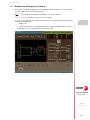
To execute a program from the USB hard drive, select the desired program and press [START]. When
the program has completed, the first lines of the program are reloaded and displayed on the screen.
This means that by pressing [START] it will execute the program again.
Removing the USB device
The USB device cannot be removed while the program is still being executed, simulated or edited.
Nor can it be removed while the program is selected.
Value Meaning
0 The tool path is drawn without displaying all the calculated points. The tool path is drawn
faster.
1 The tool path is drawn using all the calculated points. The tool path is drawn with greater
precision.
Default value: 0
Executing, simulating and editing a part-program from USB hard drive is not permitted in
conversational mode.
Executing the OPEN instruction is not permitted on the USB hard drive.
i
If the USB device is removed while a part-program is being executed, the execution will stop and an
error message will be prompted.

·20·
New features
CNC 8037
·T· MODEL
SOFT: V02.4X
To remove the USB hard drive, it must be unselected in either of the following ways:
• Executing a program from another unit (Hard drive, memory...).
• Accessing the machine parameters.
• Going into jog mode.
After unselecting the USB device, a message is displayed indicating that the USB device can now
be removed.
This feature can be disabled by setting bit 15 of the general machine parameter STARTDIS (P190)
to 1.
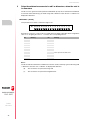
High-level EXEC instruction:
The high-level EXEC instruction cannot be executed on the USB hard drive.
Any program on the USB hard drive can execute another program found on the USB hard drive
through the EXEC high-level instruction using the respective path options.
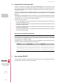
Example:
The “MAIN.PIM” program found on the USB hard drive can execute a “SECOND.PIM” program
found in the same directory on the USB hard drive, using the instruction (“./SECOND” EXEC).
MAIN.PIM
;
(EXEC "./SECOND");
M30
SECOND.PIM
(MSG ".SECOND")
G4K300
(MSG "");
M30
HARD DISK
MYDIR
- MAIN.PIM
- SECOND.PIM
The user can copy the entire MYDIR directory onto the USB hard drive and the MAIN.PIM
program will work without having to make any changes.
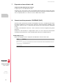
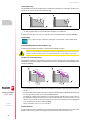
General machine parameter STARTDIS (P190)
This parameter has 16 bits counted from right to left.
Bit 15 of general parameter STARTDIS (P190).
Value Meaning
0 Enables the ability to execute a part-program from the USB hard drive.
1 Disables the ability to execute a part-program from the USB hard drive.
Default value: 0
bit
15
14 13 12 11 10 9 8 7 6 5 4 3 2 1 0
Page is loading ...
Page is loading ...
Page is loading ...
Page is loading ...
Page is loading ...
Page is loading ...
Page is loading ...
Page is loading ...
Page is loading ...
Page is loading ...
Page is loading ...
Page is loading ...
Page is loading ...
Page is loading ...
Page is loading ...
Page is loading ...
Page is loading ...
Page is loading ...
Page is loading ...
Page is loading ...
-
 1
1
-
 2
2
-
 3
3
-
 4
4
-
 5
5
-
 6
6
-
 7
7
-
 8
8
-
 9
9
-
 10
10
-
 11
11
-
 12
12
-
 13
13
-
 14
14
-
 15
15
-
 16
16
-
 17
17
-
 18
18
-
 19
19
-
 20
20
-
 21
21
-
 22
22
-
 23
23
-
 24
24
-
 25
25
-
 26
26
-
 27
27
-
 28
28
-
 29
29
-
 30
30
-
 31
31
-
 32
32
-
 33
33
-
 34
34
-
 35
35
-
 36
36
-
 37
37
-
 38
38
-
 39
39
-
 40
40


Fagor CNC 8037 para tornos Owner's manual
- Type
- Owner's manual
- This manual is also suitable for
Ask a question and I''ll find the answer in the document
Finding information in a document is now easier with AI
Related papers
-
Fagor CNC 8055 Owner's manual
-
Fagor CNC 8037 for milling machines Owner's manual
-
-
Fagor CNC 8055 for milling machines Owner's manual
-
-
Fagor CNC 8037 for lathes Owner's manual
-
-
-
-

