Yamaha PianoCraft MCR-E810 Owner's manual

Category
DVD players
Type
Owner's manual
1 To assure the finest performance, please read this manual
carefully. Keep it in a safe place for future reference.
2 Install this unit (RX-E810 and DVD-E810) in a well ventilated,
cool, dry, clean place with at least 10 cm on the top (2.5 cm for
DVD-E810), 10 cm on the left and right, and 10 cm at the back of
this unit — away from direct sunlight, heat sources, vibration,
dust, moisture, and/or cold.
3 Locate this unit away from other electrical appliances, motors, or
transformers to avoid humming sounds.
4 Do not expose this unit to sudden temperature changes from cold
to hot, and do not locate this unit in an environment with high
humidity (i.e. a room with a humidifier) to prevent condensation
inside this unit, which may cause an electrical shock, fire,
damage to this unit, and/or personal injury.
5 Avoid installing this unit where foreign object may fall onto this
unit and/or this unit may be exposed to liquid dripping or
splashing. On the top of this unit, do not place:
Other components, as they may cause damage and/or
discoloration on the surface of this unit.
Burning objects (i.e. candles), as they may cause fire, damage
to this unit, and/or personal injury.
Containers with liquid in them, as they may fall and liquid
may cause electrical shock to the user and/or damage to this
unit.
6 Do not cover this unit with a newspaper, tablecloth, curtain, etc.
in order not to obstruct heat radiation. If the temperature inside
this unit rises, it may cause fire, damage to this unit, and/or
personal injury.
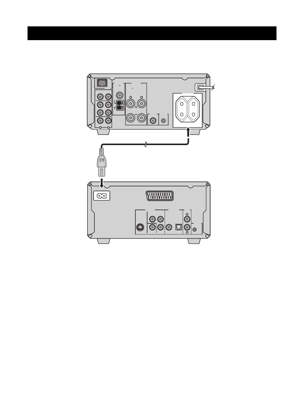
7 Do not plug in this unit to a wall outlet until all connections are
complete.
8 Do not operate this unit upside-down. It may overheat, possibly
causing damage.
9 Do not use force on switches, knobs and/or cords.
10 When disconnecting the power cable from the wall outlet, grasp
the plug; do not pull the cable.
11 Do not clean this unit with chemical solvents; this might damage
the finish. Use a clean, dry cloth.
12 Only voltage specified on this unit must be used. Using this unit
with a higher voltage than specified is dangerous and may cause
fire, damage to this unit, and/or personal injury. YAMAHA will
not be held responsible for any damage resulting from use of this
unit with a voltage other than specified.
13 Do not attempt to modify or fix this unit. Contact qualified
YAMAHA service personnel when any service is needed.
The cabinet should never be opened for any reasons.
14 When not planning to use this unit for long periods of time (i.e.
vacation), disconnect the AC power plug from the wall outlet.
15 Be sure to read the “Troubleshooting” section on common
operating errors before concluding that this unit is faulty.
16 Before moving this unit, press STANDBY/ON to set this unit in
standby mode, and disconnect the AC power plug from the wall
outlet.
17 Condensation will form when the surrounding temperature
changes suddenly. Disconnect the power cable from the outlet,
then leave the unit alone.
18 When using the unit for a long time, the unit may become warm.
Turn the power off, then leave the unit alone for cooling.
19 Install this unit near the wall outlet and where the AC power plug
can be reached easily.
DANGER
When this unit is plugged to the wall outlet, do not place your
eyes close to the opening of the disc tray and other openings to
look into inside.
For U.K. customers
If the socket outlets in the home are not suitable for the plug
supplied with this appliance, it should be cut off and an
appropriate 3 pin plug fitted. For details, refer to the instructions
described below.
The plug severed from the mains lead must be destroyed, as a
plug with bared flexible cord is hazardous if engaged in a live
socket outlet.
Special Instructions for U.K. Model
CAUTION: READ THIS BEFORE OPERATING YOUR UNIT.
This unit is not disconnected from the AC power source as
long as it is connected to the wall outlet, even if this unit itself
is turned off. This state is called the standby mode. In this
state, this unit is designed to consume a very small quantity of
power.
The laser component in this product is capable of emitting
radiation exceeding the limit for Class 1.
WARNING
TO REDUCE THE RISK OF FIRE OR ELECTRIC SHOCK,
DO NOT EXPOSE THIS APPLIANCE TO RAIN OR
MOISTURE.
Note
IMPORTANT
THE WIRES IN MAINS LEAD ARE COLOURED IN
ACCORDANCE WITH THE FOLLOWING CODE:
Blue: NEUTRAL
Brown: LIVE
As the colours of the wires in the mains lead of this appa-
ratus may not correspond with the coloured markings
identifying the terminals in your plug, proceed as follows:
The wire which is coloured BLUE must be connected to
the terminal which is marked with the letter N or coloured
BLACK. The wire which is coloured BROWN must be
connected to the terminal which is marked with the letter L
or coloured RED.
Making sure that neither core is connected to the earth
terminal of the three pin plug.
1 En
English
PREPARATIONINTRODUCTION
TUNER
OPERATIONS
OTHER
OPERATIONS
ADDITIONAL
INFORMATION
BASIC
OPERATIONS
Features .................................................................. 2
Supplied Accessories ............................................. 2
Controls and Functions......................................... 3
Receiver (RX-E810) .................................................. 3
DVD player (DVD-E810).......................................... 6
Remote control........................................................... 8
Connecting the System ........................................ 12
Connecting a TV.................................................. 14
Connecting Antennas .......................................... 15
Connecting the AM loop antenna ............................ 15
Connecting the FM antenna..................................... 15
Connecting External Components ..................... 16
Connecting an MD player or a tape deck ................ 16
Connecting an MD recorder or a CD recorder ........ 16
Connecting a YAMAHA iPod universal dock ........ 17
Connecting the Power Cables............................. 18
Setting the System................................................ 19
Step 1: Turn on the power and select
the DVD input ..................................................... 19
Step 2: Adjust the clock........................................... 19
Step 3: Set the aspect ratio....................................... 20
Step 4: Set the OSD language.................................. 20
Step 5: Set the the default audio, subtitle,
and disc menu languages ..................................... 21
Basic Receiver Operations.................................. 22
Changing the front panel display settings................ 23
Supported Disc Types.......................................... 24
Basic Disc Playback Operations......................... 25
Repeating disc playback (Repeat Play) ................... 26
Playing back randomly (Shuffle Play)..................... 26
Specifying an elapsed time for playback
(Time Search) ...................................................... 27
Specifying a preview picture for playback
(Scan Search)....................................................... 28
Customizing playback order (Program Play) .......... 29
Selecting audio and subtitle languages/
audio channel settings. ........................................ 30
Zooming the picture................................................. 30
Selecting a viewing angle ........................................ 31
Operating the disc menu .......................................... 31
Playing back MP3/WMA/JPEG/DivX discs ........... 32
Viewing or changing playback settings on the TV
(OSD menu) ........................................................ 34
Restricting Disc Playback ................................... 35
Setting the parental control level ............................. 35
Locking a disc.......................................................... 36
Changing the password............................................ 36
FM/AM Tuning .................................................... 37
Automatic tuning ..................................................... 37
Manual tuning.......................................................... 37
Automatic preset tuning........................................... 38
Manual preset tuning ............................................... 39
Selecting preset stations........................................... 39
Radio Data System Tuning
(U.K. and Europe Models Only) ..................... 40
Selecting the Radio Data System program .............. 40
Displaying the Radio Data System information ...... 41
Setting the Timer.................................................. 43
Setting the clock timer............................................. 43
Setting the sleep timer ............................................. 44
Setting the auto-standby mode............................ 45
Controlling External Components...................... 46
Available operations ................................................ 46
Setting remote control codes ................................... 48
Using iPod ............................................................... 49
Configuring the DVD Player Settings
(Setup Menu) .................................................... 51
Setup menu items..................................................... 52
Resetting the DVD player settings .......................... 56
Language Codes ................................................... 57
Troubleshooting.................................................... 58
Receiver (RX-E810) ................................................ 58
DVD player (DVD-E810)........................................ 61
Remote control ........................................................ 62
Notes on Discs ....................................................... 63
Disc information ...................................................... 63
Handling a disc ........................................................ 64
Glossary................................................................. 65
Audio information ................................................... 65
Video information.................................................... 66
Copyright and logo marks ....................................... 66
Specifications ........................................................ 67
Contents
INTRODUCTION
PREPARATION
BASIC OPERATIONS
TUNER OPERATIONS
OTHER OPERATIONS
ADDITIONAL INFORMATION
FEATURES
2 En
Receiver (RX-E810)
Maximum RMS output power per channel
65W + 65W (6 Ω, 1 kHz, 1%THD)
40-station FM/AM preset tuning
iPod dock terminal
Pure Direct mode
DVD player (DVD-E810)
Plays DVDs, Video CDs, Audio CDs, MP3 CDs,
WMA CDs, DivX CDs and JPEG CDs.
Progressive-scan video output
Optical and coaxial digital output jacks
About this manual
In this manual, “RX-E810” is described as “receiver” and “DVD-E810” is described as “DVD player”.
This manual describes how to operate the system using a remote control except when it is not available. Some of these operations are
also available using the front panel buttons.
Remote control descriptions and illustrations in this manual are based on the U.K. and Europe models unless otherwise specified.
y indicates a tip for your operation.
Notes contain important information about safety and operating instructions.
This manual is printed prior to production. Design and specifications are subject to change in part as a result of improvements, etc. In
case of differences between the manual and the product, the product has priority.
This product includes the following accessories. Before connecting this system, make sure you received all of the following parts.
Features
Supplied Accessories
STANDBY/ON
POWER
TV
1234
56
90
78
SCAN DIMMER
A-B
FREQ/TEXT
PTY SEEK
MODE START
PROG
SHUFFLETV INPUT
ON SCREEN MENU
PRESET
ENTER
A-E
DISPLAY
SLEEP
DVD/CD TUNER BAND
TAPE/MD
SUBTITLE ANGLE ZOOM AUDIO
AUX/TV DOCK
A-E
INFO.
SET UP
TV VOL VOLUME
TOP MENU
/RETURN
TV CH
REPEAT
Indoor FM antenna
(U.K., Europe, Australia,
and Korea models)
System control
cable (0.6 m)
AM loop antenna
Batteries (x2)
(AA, R06, UM-3)
Remote
control
Video pin
cable (1.5 m)
Audio pin
cable (1.5 m)
Indoor FM antenna
(U.S.A., Canada, China, Taiwan,
and Asia models)
Power cable
3 En
English
INTRODUCTION
Front panel
1 STANDBY/ON
Turns the receiver on or sets it to the standby mode (see
page 19).
2 Remote control sensor
Receives signals from the remote control.
3 DISPLAY
Switches the information shown in the front panel display
(see page 23).
4 Front panel display
Shows the various infomaiton such as the clock time or the
tuning frequency.
5 MEMORY (TIME ADJ)
Stores a preset station in the memory. Hold down this
key for more than 2 seconds to preset radio stations
automatically (see page 38).
Sets the clock before using the timer function (see
page 19).
6 AUTO/MAN’L (TIMER)
Switches between Auto Tuning mode and Manual Tuning
mode when tuner is selected as an input source (see
page 37).
Turns the clock timer function on or off (see page 43).
7 PRESET/BAND
Switches between FM, AM, and the preset mode when
tuner is selected as an input source.
8 PRESET/TUNING d / u (HOUR, MIN)
Selects a tuning frequency when tuner is selected as an
input source.
9 PURE DIRECT
Turns on or off the Pure Direct mode (see page 22).
0 TIMER LED
Lights up when the clock timer is on (see page 43).
A PHONES
Outputs audio signals for private listening with headphones.
B BASS
Adjusts the low frequency responce (see page 22).
C TREBLE
Adjusts the high frequency responce (see page 22).
D BALANCE
Adjusts the volume level of each left and right speaker
channel (see page 22).
E INPUT
Selects an input source.
F VOLUME
Adjusts the volume level.
Controls and Functions
Receiver (RX-E810)
MIN MAX
VOLUME
INPUT
BALANCE
LR
TREBLEBASS
PHONES
STANDBY/ON
TIMER
DISPLAY MEMORY
NATURAL SOUND STEREO RECEIVER RX-E810
PRESET/BAND
PRESET/TUNING
PURE DIRECT
HOURTIMER
TIME ADJ
MIN
AUTO/MAN'L
12 345 6 7 8 9
A0BCDE F
4 En
Controls and Functions
Rear panel
1 DOCK terminal
Use to connect a YAMAHA iPod universal dock (such as
YDS-10 sold separately) where your iPod can be stationed
(see page 17).
2 Antenna terminals
See page 15 for connection information.
3 Speaker terminals
See page 13 for connection information.
4 DVD/CD jacks
See page 12 for connection information.
5 TAPE/MD IN/OUT jacks
See page 16 for connection information.
6 AUX jacks
Use to connect the external components.
7 SUBWOOFER OUT jack
Use to connect the subwoofer.
8 System connector (TO DVD-E810) jack
See page 12 for connection information.
9 AC OUTLET(S)
See page 18 for connection information.
LR
LR
AC OUTLETS
SWITCHED
MAINS
SPEAKERS
DOCK
DVD/CD
TAPE/MD
AUX
OUT
IN
FM
GND
AM
ANTENNA
6
MIN / SPEAKER
TO DVD-E810
SUBWOOFER
OUT
100W MAX. TOTAL
75
UNBAL.
12 3
64
578 9
(Europe model)
5 En
Controls and Functions
English
INTRODUCTION
Front panel display
1 SLEEP indicator
Lights up when the sleep timer is on (see page 44).
2 PRESET indicator
Lights up when you preset radio stations manually (see
page 39).
3 STEREO indicator
Lights up when the receiver is receiving a strong signal
from an FM stereo broadcast.
4 AUTO indicator
Lights up when the receiver is in the Auto Tuning mode
(see page 38).
5 DOCK indicator
Lights up when you station your iPod in a YAMAHA iPod
universal dock (such as YDS-10 sold separately)
connected to the DOCK terminal of the receiver (see
page 17).
6 SHUFFLE indicator
Lights up when you set your iPod in shuffle mode.
7 REPEAT indicator
Lights up when you set your iPod in repeat mode.
8 Radio Data System indicators
(U.K. and Europe models only)
The name of the Radio Data System data offered by the
currently received Radio Data System station lights up.
PTY HOLD indicator
Lights up when the receiver is seaching for the Radio Data
System stations in the PTY SEEK mode (see page 40).
9 Multi-information display
Shows the various infomaiton such as the clock time or the
tuning frequency.
0 TIMER indicator
Flashes when the the receiver is in the clock timer setting
mode (see page 43).
A TUNED indicator
Lights up when the receiver is tuned into a station.
B MEMORY indicator
Lights up or flashes when you preset radio stations.
C iPod menu indicators
Light up the iPod menu currently selected (see page 49).
D iPod operation indicators
Show operable cursor keys when operating the iPod menu
with the menu browse mode (see page 49).
GENRES
SONGS
ALBUMS
ARTISTSPLAYLISTS
MEMORY
TUNED
TIMER
SLEEP
STEREO
AUTO
DOCK
SHUFFLE
REPEAT
PS
PTY RT CT PTY
HOLD
PRESET
1 234567 8
0AB C
D
9
6 En
Controls and Functions
Front panel
1 Disc tray
Holds a disc to be played back.
2
Opens and closes the disc tray.
3 s
Stops playback (see page 25).
4 h/e
Starts or pauses playback (see page 25).
5 STANDBY/ON
Turns the DVD player on or sets it to the standby mode
(see page 22).
6 PROGRESSIVE indicator
Lights up when the progressive scan mode is on (see
page 54).
7 Front panel display
Shows the current status of the DVD player.
8 Remote control sensor
Receives signals from the remote control.
9 b/w
Skips to the begining of the current chapter/track. Press
and hold to fast reverse (see page 25).
0 f/a
Skips to the next chapter/track. Press and hold to fast
forward (see page 25).
DVD player (DVD-E810)
STANDBY/ON
PROGRESSIVE
NATURAL SOUND DVD PLAYER DVD-E810
6 7589
2
13
4
0
7 En
Controls and Functions
English
INTRODUCTION
Rear panel
1 AV terminal (U.K. and Europe models only)
See page 14 for connection information.
2 S VIDEO jack
See page 14 for connection information.
3 VIDEO jack
See page 14 for connection information.
4 COMPONENT jacks
See page 14 for connection information.
5 COAXIAL jack
See page 16 for connection information.
6 OPTICAL jack
See page 16 for connection information.
7 AUDIO OUT jacks
See page 12 for connection information.
8 System connector (TO RX-E810) jack
See page 12 for connection information.
L
R
AV
AUDIO
OUT
DIGITAL OUT
COAXIAL
COMPONENT
S VIDEO VIDEO P
B
P
R
Y
OPTICAL
VIDEO OUT
MAINS
TO RX-E810
4 5 6 7 8
1
23
(U.K. and Europe models only)
8 En
Controls and Functions
Common functions
This remote control has two main operation modes to
control this system. Before operating functions in each
mode, you need to select a mode to change the remote
control key assignments.
To switch the operation mode
DVD/CD mode: Press DVD/CD.
TUNER mode: Press TUNER.
y
You can also operate the TV and other components (such as an
iPod) connected to the receiver using the remote control. For
details, see “Controlling External Components” on page 46.
Remote control descriptions and illustrations in this manual are
based on the U.K. and Europe models unless otherwise specified.
Operations common to all modes
The following operations are available for the receiver
when the remote control is in any operation modes.
1 Infrared signal transmitter
Sends signals to the component you want to control.
2 STANDBY/ON ( )
Turns the receiver on or sets it to the standby mode (see
page 19).
3 DISPLAY
Switches the information shown in the front panel display
(see page 23).
4 SLEEP
Sets the sleep timer on the receiver (see page 44).
5 DIMMER
Changes the brightness of the receiver’s front panel
display (see page 23).
6 VOLUME +/
Adjusts the overall volume level on the receiver.
7 Input selection keys
Select the input source on the receiver.
y
STANDBY/ON, DIMMER and SLEEP operations also control
the DVD player when the DVD player is connected to the
receiver with the supplied system control cable (see page 12).
Remote control
STANDBY/ON
POWER
TV
1234
56
90
78
SCAN
DIMMER
SLEEP
DVD/CD TUNER BAND
TAPE/MD
SUBTITLE ANGLE ZOOM AUDIO
AUX/TV
DOCK
DVD/CD
• Playback
• Subtitle and
audio language
selection, etc.
TUNER
• Radio station
tuning
• Radio station
preset, etc.
DVD/CD mode
TUNER mode
TUNER
DVD/CD
STANDBY/ON
POWER
TV
1234
56
90
78
SCAN DIMMER
A-B
PROG
SHUFFLETV INPUT
ON SCREEN MENU
PRESET
ENTER
A-E
DISPLAY
SLEEP
DVD/CD TUNER BAND
TAPE/MD
SUBTITLE ANGLE ZOOM AUDIO
AUX/TV DOCK
A-E
INFO.
SET UP
TV VOL VOLUME
TOP MENU
/RETURN
TV CH
REPEAT
1
2
3
4
5
6
7
FREQ/TEXT
PTY SEEK
MODE START
Note
9 En
Controls and Functions
English
INTRODUCTION
DVD/CD mode
Operations available in DVD/CD mode
The following operations are available for the DVD
player.
y
Press DVD/CD to set the remote control to the DVD/CD mode
before carrying out the following operations.
1 REPEAT
Selects the Repeat Play mode (see page 26).
2 s
Stops playback (see page 25).
3 e
Pauses playback (see page 25).
4 h
Starts playback (see page 25).
5 b, a
Skips to the beginning of the current chapter/track or next
chapter/track. Press and hold to fast reverse or fast forward
(see page 25).
6 ON SCREEN (INFO.)
Displays the OSD menu on the TV screen or switches the
time display of CDs (see page 34).
7 SET UP
Displays the setup menu on the TV screen (see page 51).
8 SUBTITLE
Selects the subtitle language (see page 30).
9 ANGLE
Selects a viewing angle (see page 31).
0 Number keys (1 to 9, 0)
Input numerals to specify parameters or chapter/track
numbers.
A SCAN
Previews the content of a DVD or VCD (see page 28) or
plays back the first few seconds of each track on a CD (see
page 25).
B A-B
Repeats a specified section within a chapter/track (see
page 26).
C PROG
Displays the program list used for the Program Play
feature (see page 29).
D SHUFFLE
Turns on/off the Shuffle Play feature (see page 26).
E MENU
Displays the DVD menu (see page 31) or PBC menu of a
VCD (see page 31).
F TOP MENU/RETURN
Returns to the top of the DVD menu (see page 31) or to
the previous PBC menu (see page 31). Press and hold to
return to the previous DVD menu.
G Cursor keys ( / / / ), ENTER
Selects an item in the menu screen or specify the selected
parameter.
H AUDIO
Selects the audio language (see page 30).
I ZOOM
Zooms in a specified part of picture (see page 30).
STANDBY/ON
POWER
TV
1234
56
90
78
SCAN DIMMER
A-B
PROG
SHUFFLETV INPUT
ON SCREEN MENU
PRESET
ENTER
A-E
DISPLAY
SLEEP
DVD/CD TUNER BAND
TAPE/MD
SUBTITLE ANGLE ZOOM AUDIO
AUX/TV DOCK
A-E
INFO.
SET UP
TV VOL VOLUME
TOP MENU
/RETURN
TV CH
REPEAT
FREQ/TEXT
PTY SEEK
MODE START
0
A
B
C
D
E
F
G
H
I
1
2
3
4
5
6
7
8
9
10 En
Controls and Functions
TUNER mode Operations available in TUNER mode
The following operations are available for the receiver.
y
Press TUNER to set the remote contol to the TUNER mode
before carrying out the following operations.
1 Number keys (1 to 8)
Selects preset station number (see page 39).
2 Radio Data System tuning keys
(U.K. and Europe models only)
FREQ/TEXT
Switches the Radio Data System display between the
PS mode, PTY mode, RT mode, CT mode (if the
station offers the corresponding data services) and the
frequency display (see page 41).
PTY SEEK MODE
Sets the receiver to the PTY SEEK mode (see
page 40).
PTY SEEK START
Starts searching for a station once the desired
program type is selected in the PTY SEEK mode (see
page 40).
3 A-E / , PRESET /
Press A-E / to select a preset station group (A to E)
and PRESET / to select a preset station number
(1 to 8) (see page 39).
4 BAND
Switches the radio reception mode between FM, AM and
the preset mode.
STANDBY/ON
POWER
TV
1234
56
90
78
SCAN DIMMER
A-B
PROG
SHUFFLETV INPUT
ON SCREEN MENU
PRESET
ENTER
A-E
DISPLAY
SLEEP
DVD/CD TUNER BAND
TAPE/MD
SUBTITLE ANGLE ZOOM AUDIO
AUX/TV DOCK
A-E
INFO.
SET UP
TV VOL VOLUME
TOP MENU
/RETURN
TV CH
REPEAT
1
2
3
FREQ/TEXT
PTY SEEK
MODE START
4
11 En
Controls and Functions
English
INTRODUCTION
Installing the batteries in the remote
control
1 Press the mark on the battery cover and
open the cover.
2 Insert the two supplied batteries (AA, R06,
UM-3) into the battery compartment.
Make sure you insert the batteries according to the
polarity markings (+ and –).
3 Close the battery cover.
Do not use an old battery together with new one.
Do not use different types of batteries (for example, alkaline
and manganese) together. Each type of battery has its own
characteristics even if they are similar in shape.
If the batteries run out, immediately remove them from the
remote control to prevent an explosion or acid leak.
Dispose of the batteries according to the regional regulations.
If a battery starts leaking, dispose of it immediately. Be careful
not to let leaking battery acid come into contact with your skin
or clothing. Before inserting new batteries, wipe the
compartment clean.
Replace the batteries within two minutes to preserve the
memory in the remote control.
Using the remote control
Use the remote control within 6 m (20 feet) of the
component you want to control and point it toward its
remote control sensor (see pages 3 and 6).
Be careful not to spill liquid on the remote control.
Be careful not to drop the remote control.
Do not leave the remote control in the following places:
hot or humid places, such as near a heater or in a bathroom
extremely cold places
dusty places
Notes
Press
Notes
MIN MAX
VOLUME
INPUT
BALANCE
LR
TREBLEBASS
PHONES
STANDBY/ON
TIMER
DISPLAY MEMORY
NATURAL SOUND STEREO RECEIVER RX-E810
PRESET/BAND
PRESET/TUNING
PURE DIRECT
HOURTIMER
TIME ADJ
MIN
AUTO/MAN'L
30˚ 30˚
Within 6 m
(20 feet)
CONNECTING THE SYSTEM
12 En
Make sure you read the following procedure and notes carefully before connecting the system. For information on the
speakers (NX-E800), refer to the owner’s manual supplied with it.
Do not connect the power cable of the receiver, DVD player, or other components to the wall outlet until all cable connections are
completed.
1 Connect the DVD/CD (L/R) jacks of the receiver to the AUDIO OUT (L/R) jacks of the DVD player using the
supplied audio pin cable.
2 Connect the system connector (TO DVD-E810) jack of the receiver to the system connector (TO RX-E810) jack of
the DVD player using the supplied system control cable.
3 Connect the speaker terminals (L) of the receiver to the speaker terminals of the left speaker and the speaker terminals
(R) of the receiver to the speaker terminals of the right speaker using the speaker cables supplied with the speaker set
(NX-E800). See page 13 for details.
y
The system control connection is used to synchronize the specific operations between the receiver and the DVD player.
If you want to connect an amplifier with a digital input instead of the RX-E810, use the DIGITAL OUT (COAXIAL or OPTICAL)
jacks of the DVD player and configure the “DIGITAL OUTPUT” setting in the setup menu (see page 52).
Connecting the System
Note
L
R
AV
AUDIO
OUT
DIGITAL OUT
COAXIAL
COMPONENT
S VIDEO VIDEO P
B
P
R
Y
OPTICAL
VIDEO OUT
MAINS
TO RX-E810
LR
LR
MAINS
SPEAKERS
DOCK
DVD/CD
TAPE/MD
AUX
OUT
IN
FM
GND
AM
ANTENNA
75
UNBAL.
TO DVD-E810
SUBWOOFER
OUT
100W MAX. TOTAL
AC OUTLETS
SWITCHED
6
MIN / SPEAKER
1
3
3
2
Receiver (RX-E810)
(Europe model)
DVD player (DVD-E810)
Left speaker
(NX-E800)
Right speaker
(NX-E800)
Connecting the System
13 En
English
PREPARATION
Connecting the speaker cable
Be sure to connect the left channel (L), right channel (R), “+”
(red) and “–” (black) properly. If the connections are faulty, no
sound will be heard from the speakers, and if the polarity of the
speaker connections is incorrect, the sound will be unnatural
and lack bass.
Do not let the bare speaker wires touch each other or do not let
them touch any metal part of the receiver. This could damage
the receiver and/or the speakers.
When connecting another speaker set instead of the NX-E800,
be sure to use speakers with the specified impedance shown on
the rear panel of the receiver and magnetically shielded. In case
the magnetically shielded speakers interfere with the monitor,
place the speakers away from the monitor.
1 Remove approximately 10 mm (3/8 in) of
insulation from the end of each speaker
cable and then twist the exposed wires of the
cable together to prevent short circuits.
2 Unscrew the knob.
3 Insert the bare wire into the terminal.
4 Tighten the knob to secure the wire.
Notes
10 mm (3/8 in)
Red: positive (+)
Black: negative (–)
Red: positive (+)
Black: negative (–)
Red: positive (+)
Black: negative (–)
CONNECTING A TV
14 En
Follow the procedure below to connect your TV to the DVD player using the supplied video pin cable. Also, you can
enjoy high-quality pictures with a S-video connection, a component video connection or a scart connection (U.K. and
Europe models only) using a corresponding commercially available cable. For information on your TV, refer to the
owner’s manual supplied with it.
Do not connect the power cable of the receiver, DVD player, or other components to the wall outlet until all cable connections are
completed.
Connect the VIDEO jack of the DVD player to the
video input jack of your TV using the supplied
video pin cable.
y
To enjoy TV sounds with the receiver, connect AUX (L/R) jacks
of the receiver to the audio output jacks of your TV using a
commercially available audio pin cable.
Component video connection
Connect the COMPONENT jacks of the DVD player to
the component video input jacks of your TV using a
commercially available component video cable.
(U.K. and Europe models only)
When you make a component video connection, set
“COMPONENT” to “YUV” in the setup menu of the DVD player
(see page 54).
S-video connection
Connect the S VIDEO jack of the DVD player to the
S-video input jack of your TV using a commercially
available S-video cable.
Scart connection
(U.K. and Europe models only)
Connect the AV terminal of the DVD player to the scart
input terminal of your TV using a commercially available
scart cable.
(U.K. and Europe models only)
When you make a scart connection, set “COMPONENT” to
“RGB” in the setup menu of the DVD player (see page 54).
Connecting a TV
Note
Note
L
R
AV
AUDI O
OUT
DIGITAL OUT
COAXIAL
COMPONENT
S VIDEO VIDEO P
B
P
R
Y
OPTICAL
VIDEO OUT
MAINS
TO RX-E810
IN
VIDEO
Video pin cable
(supplied)
DVD player
TV
L
R
AV
AUDI O
OUT
DIGITAL OUT
COAXIAL
COMPONENT
S VIDEO VIDEO P
B
P
R
Y
OPTICAL
VIDEO OUT
TO RX-E810
COMPONENT jacks
Note
L
R
AV
AUDIO
OUT
DIGITAL OUT
COAXIAL
COMPONENT
S VIDEO VIDEO P
B
P
R
Y
OPTICAL
VIDEO OUT
TO RX-E810
S VIDEO jack
L
R
AV
AUDIO
OUT
DIGITAL OUT
COAXIAL
COMPONENT
S VIDEO VIDEO P
B
P
R
Y
OPTICAL
VIDEO OUT
TO RX-E810
(U.K. and Europe models only)
AV terminal
CONNECTING ANTENNAS
15 En
English
PREPARATION
To enjoy radio on the receiver, connect the supplied AM and FM antennas to the designated terminals. If there is a
problem of weak radio wave reception in your area or you want to improve radio reception, we recommend that you use
optional outdoor antennas. For details, consult the nearest authorized YAMAHA dealer or service center.
Be sure to set the tuner frequency step (Asia and Taiwan models only) according to the frequency spacing in your area (see page 38).
About grounding
For maximum safety and minimum interference, connect
the antenna GND terminal to a good earth ground. A good
earth ground is a metal stake driven into moist earth.
1 Attach the antenna stand to the antenna.
When attaching the antenna to the wall, you do not
need to use the antenna stand.
2 Press down the tab of the AM terminal.
Depending on the product, the shape of the tab is different from
the described illust.
3 Insert the AM loop antenna lead wires into
the AM terminal.
4 Replace the tab back to secure the wire.
5 Repeat steps 2 to 4 to insert the AM loop
antenna lead wires into the GND terminal.
6 Place the antenna away from the receiver and
speaker cables.
While listening to the radio, rotate the antenna head
to find the best angle for reception.
1 Connect the supplied indoor FM antenna to
the FM jack of the receiver.
2 Place the antenna away from the receiver and
speaker cables.
Connecting Antennas
Note
Connecting the AM loop antenna
LR
LR
SPEAKERS
DOCK
DVD/CD
TAPE/MD
AUX
OUT
IN
FM
GND
AM
ANTENNA
75
UNBAL.
6
MIN / SPEAKER
Indoor FM
antenna
(supplied)
AM loop
antenna
(supplied)
Ground
(GND terminal)
Note
Connecting the FM antenna
CONNECTING EXTERNAL COMPONENTS
16 En
You can connect various audio components, such as an MD player, a tape deck or a YAMAHA iPod universal dock to the
receiver. Also you can connect an MD recorder or a CD recorder to the DVD player using the DIGITAL OUT jacks. For
information on your external component, refer to the owner’s manual supplied with each component.
Do not connect the power cable of the receiver, DVD player, or other components to the wall outlet until all cable connections are
completed.
If you connect an MD player or a tape deck to the receiver,
you can enjoy audio sources played on the component.
1 Connect the TAPE/MD IN (L/R) jacks of the
receiver to the analog output jacks of an MD
player or a tape deck using a commercially
available audio pin cable.
2 To record audio output from the receiver,
connect the TAPE/MD OUT (L/R) jacks of the
receiver to the analog input jacks of an MD
player or a tape deck using a commercially
available audio pin cable.
If you connect an MD recorder or a CD recorder to the
DVD player with a digital connection, you can make a
digital recording.
Connect the DIGITAL OUT (COAXIAL or
OPTICAL) jack of the DVD player to the digital
input (coaxial or optical) jack of an MD recorder
or a CD recorder using a commercially available
coaxial or optical cable.
The DIGITAL OUT jacks are compatible with PCM, Dolby
Digital and DTS signals.
The DIGITAL OUT (OPTICAL) jack is designed based on EIA
standards. To make a digital connection, use an optical cable
that meets EIA standards.
Connecting External Components
Note
Connecting an MD player or a tape
deck
LR
DOCK
DVD/CD
TAPE/MD
AUX
OUT
IN
FM
GND
AM
ANTENNA
75
UNBAL.
L
R
ANALOG
OUTIN
MD player or
tape deck
Audio pin cable
Receiver
Connecting an MD recorder or a CD
recorder
Notes
L
R
AV
AUDIO
OUT
DIGITAL OUT
COAXIAL
COMPONENT
VIDEO P
B
P
R
Y
OPTICAL
VIDEO OUT
TO RX-E810
COAXIAL OPTICAL
MD recorder or
CD recorder
DVD player
Optical cable
or
Coaxial cable
Connecting External Components
17 En
English
PREPARATION
The receiver (RX-E810) is equipped with the DOCK terminal on the rear panel that allows you to connect a YAMAHA
iPod universal dock (such as YDS-10 sold separately) where you can station your iPod and control playback of your iPod
using the supplied remote control. Connect a YAMAHA iPod universal dock (such as YDS-10 sold separately) to the
DOCK terminal on the rear of the receiver using its dedicated cables. Once the connection is complete, station your iPod
in the YAMAHA iPod universal dock.
Do not connect the power cable of the receiver, DVD player, or other components to the wall outlet until all cable connections are
completed.
Only iPod (Click and Wheel), iPod nano, and iPod mini are supported.
You need a YAMAHA iPod universal dock (such as YDS-10 sold separately) and its dedicated cable compatible with the DOCK
terminal of the receiver.
Do not connect any iPod accessories (such as headphones, a wired remote control, or an FM transmitter) to your iPod when it is
stationed in a YAMAHA iPod universal dock (such as YDS-10 sold separately).
Unless your iPod is firmly stationed in a YAMAHA iPod universal dock (such as YDS-10 sold separately) connected to the DOCK
terminal of the receiver, audio signals may not be output properly.
Once the connection between your iPod and the receiver is complete and the receiver is set to DOCK mode (see page 47), “iPod
connected” appears in the front panel display. If the connection between your iPod and the receiver fails, a status message appears in
the front panel display. For a complete list of connection status message, see the iPod section in “Troubleshooting” on page 60.
Your iPod battery is automatically charged when your iPod is stationed in a YAMAHA iPod universal dock (such as YDS-10 sold
separately) connected to the DOCK terminal of the receiver as long as the receiver is turned on.
Depending on the type of the iPod, you may need to insert one of the iPod adapters supplied with a YAMAHA iPod universal dock
(such as YDS-10 sold separately) into the dock slot before you station your iPod.
Connecting a YAMAHA iPod universal dock
Notes
LR
LR
AC OUTLETS
SWITCHED
MAINS
SPEAKERS
DOCK
DVD/CD
TAPE/MD
AUX
OUT
IN
FM
GND
AM
ANTENNA
75
UNBAL.
TO DVD-E810
SUBWOOFER
OUT
100W MAX. TOTAL
6
MIN / SPEAKER
Receiver
(Europe model)
YAMAHA iPod universal dock
(such as YDS-10 sold separately)
iPod
CONNECTING THE POWER CABLES
18 En
Once all connections are complete, connect the power cable of the DVD player to the AC OUTLET(S) terminal on the
rear of the receiver (or the AC wall outlet if the AC OUTLET(S) terminal is not available), and then plug the power cable
of the receiver into the AC wall outlet.
AC OUTLET(S) (SWITCHED)
U.K. and Australia models ..................................... 1 outlet
Korea model ...............................................................None
Other models .........................................................2 outlets
Use these outlet(s) to supply power to the DVD player or any connected components. Connect the power cable of your
other components to these outlet(s). Power to these outlet(s) is supplied when the receiver is turned on. For information
on the maximum power or the total power consumption of the components that can be connected to these outlet(s), see
“Specifications” on page 67.
Connecting the Power Cables
L
R
AV
AUDIO
OUT
DIGITAL OUT
COAXIAL
COMPONENT
S VIDEO VIDEO P
B
P
R
Y
OPTICAL
VIDEO OUT
MAINS
TO RX-E810
LR
LR
AC OUTLETS
SWITCHED
MAINS
SPEAKERS
DOCK
DVD/CD
TAPE/MD
AUX
OUT
IN
FM
GND
AM
ANTENNA
6 MIN /
SPEAKER
TO DVD-E810
SUBWOOFER
OUT
100W MAX. TOTAL
75
UNBAL.
DVD player
Receiver
(Europe model)
To the AC wall outlet
To AC OUTLET(S) on the
rear panel of the receiver
(or the AC wall outlet)
Power cable
SETTING THE SYSTEM
19 En
English
PREPARATION
Before starting playback operation, follow the procedure below to configure the system settings.
1 Turn on your TV and then press STANDBY/
ON to turn on the receiver.
If the DVD player is connected to the receiver with
the system control cable, the DVD player turns on
automatically. Otherwise, press STANDBY/ON on
the front panel of the DVD player to turn on it.
The front panel display of each component lights up.
2 Press DVD/CD to select “DVD/CD” as an
input source.
3 On your TV, select the input to which the DVD
player is connected (EXT1, AV1, etc.). For
details, refer to the manual supplied with
your TV.
The default screen appears on the TV screen.
If the picture is distorted on your TV, the color system (NTSC and
PAL) setting of the DVD player may not match your TV.
To switch the color system setting in such case, press and then
AUDIO while the disc tray is open.
1 Press DISPLAY on the front panel of the
receiver.
“Clock Time” appears in the front panel display for a
few seconds, and then “Set Clock” appears.
2 Press TIME ADJ for about two seconds to
enter the clock setting mode.
3 To set the hour setting ahead, press HOUR
repeatedly. To set the hour setting backward,
press HOUR repeatedly while holding down
PRESET/BAND.
4 To set the minute setting ahead, press MIN
repeatedly. To set the minute setting
backward, press MIN repeatedly while
holding down PRESET/BAND.
Setting the System
Step 1: Turn on the power and
select the DVD input
Note
STANDBY/ON
POWER
TV
1234
56
90
78
SCAN DIMMER
AB
REPEAT
SLEEP
DVD/CD TUNER BAND
TAPE/MD
SUBTITLE ANGLE ZOOM AUDIO
AUX/TV
DOCK
STANDBY/ON
DVD/CD
Step 2: Adjust the clock
MIN MAX
VOLU ME
INPUT
BALANCE
LR
TREBLEBASS
PHONES
STANDBY/ON
TIMER
DISPLAY MEMORY
NATURAL SOUND STEREO RECEIVER RX-E810
PRESET/BAND
PRESET/TUNING
PURE DIRECT
HOURTIMER
TIME ADJ
MIN
AUTO/MAN'L
DISPLAY HOUR
MIN
TIME ADJ
PRESET/BAND
  • Page 1 1
  • Page 2 2
  • Page 3 3
  • Page 4 4
  • Page 5 5
  • Page 6 6
  • Page 7 7
  • Page 8 8
  • Page 9 9
  • Page 10 10
  • Page 11 11
  • Page 12 12
  • Page 13 13
  • Page 14 14
  • Page 15 15
  • Page 16 16
  • Page 17 17
  • Page 18 18
  • Page 19 19
  • Page 20 20
  • Page 21 21
  • Page 22 22
  • Page 23 23
  • Page 24 24
  • Page 25 25
  • Page 26 26
  • Page 27 27
  • Page 28 28
  • Page 29 29
  • Page 30 30
  • Page 31 31
  • Page 32 32
  • Page 33 33
  • Page 34 34
  • Page 35 35
  • Page 36 36
  • Page 37 37
  • Page 38 38
  • Page 39 39
  • Page 40 40
  • Page 41 41
  • Page 42 42
  • Page 43 43
  • Page 44 44
  • Page 45 45
  • Page 46 46
  • Page 47 47
  • Page 48 48
  • Page 49 49
  • Page 50 50
  • Page 51 51
  • Page 52 52
  • Page 53 53
  • Page 54 54
  • Page 55 55
  • Page 56 56
  • Page 57 57
  • Page 58 58
  • Page 59 59
  • Page 60 60
  • Page 61 61
  • Page 62 62
  • Page 63 63
  • Page 64 64
  • Page 65 65
  • Page 66 66
  • Page 67 67
  • Page 68 68
  • Page 69 69
  • Page 70 70
  • Page 71 71
  • Page 72 72
  • Page 73 73
  • Page 74 74
  • Page 75 75
  • Page 76 76
  • Page 77 77
  • Page 78 78
  • Page 79 79
  • Page 80 80
  • Page 81 81
  • Page 82 82
  • Page 83 83
  • Page 84 84
  • Page 85 85
  • Page 86 86
  • Page 87 87
  • Page 88 88
  • Page 89 89
  • Page 90 90
  • Page 91 91
  • Page 92 92
  • Page 93 93
  • Page 94 94
  • Page 95 95
  • Page 96 96
  • Page 97 97
  • Page 98 98
  • Page 99 99
  • Page 100 100
  • Page 101 101
  • Page 102 102
  • Page 103 103
  • Page 104 104
  • Page 105 105
  • Page 106 106
  • Page 107 107
  • Page 108 108
  • Page 109 109
  • Page 110 110
  • Page 111 111
  • Page 112 112
  • Page 113 113
  • Page 114 114
  • Page 115 115
  • Page 116 116
  • Page 117 117
  • Page 118 118
  • Page 119 119
  • Page 120 120
  • Page 121 121
  • Page 122 122
  • Page 123 123
  • Page 124 124
  • Page 125 125
  • Page 126 126
  • Page 127 127
  • Page 128 128
  • Page 129 129
  • Page 130 130
  • Page 131 131
  • Page 132 132
  • Page 133 133
  • Page 134 134
  • Page 135 135
  • Page 136 136
  • Page 137 137
  • Page 138 138
  • Page 139 139
  • Page 140 140
  • Page 141 141
  • Page 142 142
  • Page 143 143
  • Page 144 144
  • Page 145 145
  • Page 146 146
  • Page 147 147
  • Page 148 148
  • Page 149 149
  • Page 150 150
  • Page 151 151
  • Page 152 152
  • Page 153 153
  • Page 154 154
  • Page 155 155
  • Page 156 156
  • Page 157 157
  • Page 158 158
  • Page 159 159
  • Page 160 160
  • Page 161 161
  • Page 162 162
  • Page 163 163
  • Page 164 164
  • Page 165 165
  • Page 166 166
  • Page 167 167
  • Page 168 168
  • Page 169 169
  • Page 170 170
  • Page 171 171
  • Page 172 172
  • Page 173 173
  • Page 174 174
  • Page 175 175
  • Page 176 176
  • Page 177 177
  • Page 178 178
  • Page 179 179
  • Page 180 180
  • Page 181 181
  • Page 182 182
  • Page 183 183
  • Page 184 184
  • Page 185 185
  • Page 186 186
  • Page 187 187
  • Page 188 188
  • Page 189 189
  • Page 190 190
  • Page 191 191
  • Page 192 192
  • Page 193 193
  • Page 194 194
  • Page 195 195
  • Page 196 196
  • Page 197 197
  • Page 198 198
  • Page 199 199
  • Page 200 200
  • Page 201 201
  • Page 202 202
  • Page 203 203
  • Page 204 204
  • Page 205 205
  • Page 206 206
  • Page 207 207
  • Page 208 208
  • Page 209 209
  • Page 210 210
  • Page 211 211
  • Page 212 212
  • Page 213 213
  • Page 214 214
  • Page 215 215
  • Page 216 216
  • Page 217 217
  • Page 218 218
  • Page 219 219
  • Page 220 220
  • Page 221 221
  • Page 222 222
  • Page 223 223
  • Page 224 224
  • Page 225 225
  • Page 226 226
  • Page 227 227
  • Page 228 228
  • Page 229 229
  • Page 230 230
  • Page 231 231
  • Page 232 232
  • Page 233 233
  • Page 234 234
  • Page 235 235
  • Page 236 236
  • Page 237 237
  • Page 238 238
  • Page 239 239
  • Page 240 240
  • Page 241 241
  • Page 242 242
  • Page 243 243
  • Page 244 244
  • Page 245 245
  • Page 246 246
  • Page 247 247
  • Page 248 248
  • Page 249 249
  • Page 250 250
  • Page 251 251
  • Page 252 252
  • Page 253 253
  • Page 254 254
  • Page 255 255
  • Page 256 256
  • Page 257 257
  • Page 258 258
  • Page 259 259
  • Page 260 260
  • Page 261 261
  • Page 262 262
  • Page 263 263
  • Page 264 264
  • Page 265 265
  • Page 266 266
  • Page 267 267
  • Page 268 268
  • Page 269 269
  • Page 270 270
  • Page 271 271
  • Page 272 272
  • Page 273 273
  • Page 274 274
  • Page 275 275
  • Page 276 276
  • Page 277 277

Yamaha PianoCraft MCR-E810 Owner's manual

Category
DVD players
Type
Owner's manual

Ask a question and I''ll find the answer in the document

Finding information in a document is now easier with AI