- 3 -
M985000 Rev. 1.0 (3/20)
7
CARE INSTRUCTIONS:
DO: SIMPLY RINSE THE PRODUCT CLEAN WITH CLEAR WATER. DRY WITH A SOFT COTTON FLANNEL CLOTH.
DO NOT: DO NOT CLEAN THE PRODUCT WITH SOAPS, ACID, POLISH, ABRASIVES, HARSH CLEANERS, OR A
CLOTH WITH A COARSE SURFACE.
6
5
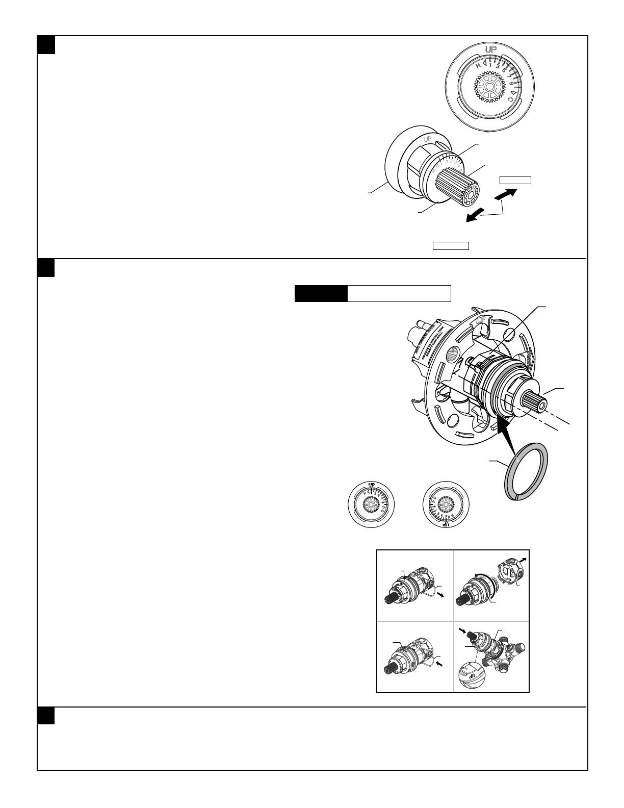
• By restricting HANDLE rotation and limiting the amount of hot water
allowed to mix with the cold, the HOT LIMIT SAFETY STOP (1)
reduces risk of accidental scalding. To set the maximum hot water
temperature of your faucet valve, adjust the setting on the HOT LIMIT
SAFETY STOP (1).
• Turn CARTRIDGE STEM (2) to the OFF position (coldest setting) before
making adjustment to HOT LIMIT STOP (1). Pull forward and rotate
counterclockwise one number to limit hot water temperature.
Use NUMBERS (5) on CARTRIDGE (4) on HOT LIMIT STOP (1)
for indication.
ADJUST HOT LIMIT STOP
COLDER
(Larger Numbers)
1 2 3 4 5 6 7 8 9 10
HOTTER
(Smaller Numbers)
1 2 3 4 5 6 7 8 9 10
3
4
1
5
2
VALVE LEAKS WHEN SHUT OFF
• Remove CARTRIDGE, see STEP 1 and STEP 2 and REVERSE
process.
• Clean SEALS on the side of CARTRIDGE. Clean inside sealing
surface of VALVE BODY.
• Re-assemble CARTRIDGE. Install trim. Turn on water supply and
check for leaks.
REPLACING CARTRIDGE
• To remove CARTRIDGE (1), install split WASHER (3) between the
ridge on the cartridge and the bonnet nut.
(only supplied with replacement cartridge). as shown.
• Proceed to unthread BONNET NUT (2) counter clockwise.
Note: CARTRIDGE (1) should be pulling out while unthreading
BONNET NUT (2).
• Upon removal of the old Cartridge, install a new cartridge
and secure it with BONNET NUT (Hand tighten).
BACK TO BACK INSTALLATION
• Remove CARTRIDGE (B) as detailed in steps above.
• Remove PIN (A) from CARTRIDGE (B) by pulling.
• Separate MANIFOLD (C) from CARTRIDGE (B) by pulling.
• Rotate CARTRIDGE (B) 180 degrees and reinstall MANIFOLD (C)
with PIN (A).
• The “UP” TEXT (D) should now be facing downward during
installation of the CARTRIDGE (B).
• Remove HANDLE (see step 3 and reverse).
• Remove ESCUTCHEON and CARTRIDGE CAP (see step 1 and reverse).
SERVICE
TO GAIN ACCESS TO VALVE FOR SERVICING
CAUTION
Turn off hot and cold water
supplies before beginning.
1
3
2
B
A
B
C
180º
B
A
B
D
1 2
3 4
BACK TO BACK INSTALLATION
Standard
Back to Back


