Palazzetti Ecofire Adagio Installation, User And Maintenance Manual
- Category
- Stoves
- Type
- Installation, User And Maintenance Manual

ECOFIRE® ADAGIO
EASY TOUCH
MANUALE DI INSTALLAZIONE USO E MANUTENZIONE
INSTALLATION, USER AND MAINTENANCE MANUAL
INSTALLATIONS, BEDIENUNGS UND WARTUNGSANLEITUNGEN
NOTICE D’INSTALLATION
MANUAL DE INSTALACIÓN, USO Y MANTENIMIENTO


cod. 00 477 2290 - 07/2013 - Palazzetti - PN - Italy 3/136
Gentile cliente,
desideriamo innanzitutto ringraziarLa per la preferenza che ha voluto accordarci acquistando
il nostro prodotto e ci congratuliamo con Lei per la scelta.
Per consentirLe di utilizzare al meglio la Sua nuova stufa, la invitiamo a seguire attentamente
quanto descritto nel presente manuale.
IT
Dear Customer,
We’d like to thank you for having purchased one of our products and congratulate you on
your choice.
To make sure you get the most out of your new stove, please carefully follow the instructions
provided in this manual.
Sehr geehrter Kunde,
Zuallererst möchten wir Ihnen für den uns gewährten Vorzug danken und Ihnen zur Wahl
gratulieren.
Damit Sie Ihren neuen Heizofen so gut wie möglich benutzen können, bitten wir Sie, die in
dieser Bedienungs- und Wartungsanleitung enthaltenen Angaben genau zu befolgen.
Cher client,
Nous souhaitons avant tout vous remercier de la préférence que vous nous avez accordée
en achetant notre produit et vous félicitions pour votre choix.
suivre attentivement les instructions reportées dans cette notice.
Estimado Cliente,
Deseamos agradecerle por la preferencia que nos ha otorgado adquiriendo nuestro producto
y lo felicitamos por su elección.
Para el mejor uso de su nueva estufa, lo invitamos a leer con atención cuanto se describe
en el presente manual.
GB
DE
F
ES

30/136 cod. 00 477 2290 - 07/2013 - Palazzetti - PN - Italy
USE AND MAINTENANCE
SHUNTER
TRANSPORTER
INSTALLER
ASSISTANCE
CENTER
ELECTRICIAN
USER
SUMMARY FOR SKILLS
1 INTRODUCTION ..............................................................................................................32
2 SAFETY WARNINGS .......................................................................................................34
4 HANDLING AND TRANSPORT ......................................................................................35
7 STOVE DESCRIPTION ....................................................................................................43
8 PRELIMINARY OPERATIONS ........................................................................................46
9 STOVE OPERATION .......................................................................................................48
10 FUNCTIONS AVAILABLE ..............................................................................................49
11 ALARM MANAGEMENT ................................................................................................51
12 MAINTENANCE .............................................................................................................52
13 DECOMMISSIONING AND DISPOSAL .........................................................................54
1 INTRODUCTION ..............................................................................................................32
2 SAFETY WARNINGS .......................................................................................................34
3 FUEL SPECIFICATIONS .................................................................................................35
4 HANDLING AND TRANSPORT ......................................................................................35
5 INSTALLATION SITE PREPARATION ............................................................................36
6 INSTALLATION ................................................................................................................40
7 STOVE DESCRIPTION ....................................................................................................43
8 PRELIMINARY OPERATIONS ........................................................................................46
12 MAINTENANCE .............................................................................................................52
13 DECOMMISSIONING AND DISPOSAL .........................................................................54
1 INTRODUCTION ..............................................................................................................32
2 SAFETY WARNINGS .......................................................................................................34
3 FUEL SPECIFICATIONS .................................................................................................35
4 HANDLING AND TRANSPORT ......................................................................................35
13 DECOMMISSIONING AND DISPOSAL .........................................................................54

cod. 00 477 2290 - 07/2013 - Palazzetti - PN - Italy 31/136
ENGLISH
USE AND MAINTENANCE
INDEX
1 INTRODUCTION 32
1.1 SYMBOLS 32
1.2 INTENDED USE 32
1.3 PURPOSE AND CONTENTS OF THIS MANUAL 32
1.4 HOW TO KEEP THIS MANUAL 32
1.5 UPDATES TO THE MANUAL 32
1.6 GENERAL INFORMATION 32
1.7 MAIN REFERENCE STANDARDS 32
1.8 PRODUCT WARRANTY 33
1.9 MANUFACTURER’S LIABILITY 33
1.10 INTENDED USERS 33
1.11 TECHNICAL SERVICE 33
1.12 SPARE PARTS 33
1.13 IDENTIFICATION LABEL 33
1.14 DELIVERY OF THE STOVE 33
2 SAFETY WARNINGS 34
2.1 INSTALLATION WARNINGS 34
2.2 MAINTENANCE WARNINGS 34
2.3 WARNINGS FOR THE USER 34
3 FUEL SPECIFICATIONS 35
3.1 FUEL SPECIFICATIONS 35
3.2 STORING THE PELLETS 35
4 HANDLING AND TRANSPORT 35
4.1 REMOVING THE STOVE FROM THE PALLET 35
5 INSTALLATION SITE PREPARATION 36
5.1 GENERAL INFORMATION 36
5.2 SAFETY PRECAUTIONS 36
5.3 STOVE INSTALLATION SITE 36
5.4 COMBUSTION AIR 37
5.5 FLUE GAS EXHAUST 38
6 INSTALLATION 40
6.1 LEVELLING THE STOVE 40
6.2 SYSTEM CONNECTIONS 40
6.3 INITIAL CONFIGURATION 41
7 STOVE DESCRIPTION 43
7.1 CONTROL PANEL 43
7.2 USING THE CONTROL PANEL 44
7.3 OPERATING PARAMETERS 45
8 PRELIMINARY OPERATIONS 46
8.1 LOADING THE PELLETS 46
8.2 POWER SUPPLY 46
8.3 INITIAL SETTINGS 46
9 STOVE OPERATION 48
9.1 STARTING THE STOVE 48
9.2 MODIFYING THE PARAMETERS 48
9.3 SWITCHING OFF 48
9.4 OPERATION WITH ROOM THERMOSTAT 48
9.5 OPERATION WITH ROOM PROBE ON THE STOVE 48
10 FUNCTIONS AVAILABLE 49
10.1 TIMER 49
10.2 “ECO MODE” SAVING FUNCTION 49
10.3 RESTART DELTA FUNCTION 50
10.4 AUTONOMY FUNCTION 50
10.5 REFILL FUNCTION 50
10.6 RESTARTING AFTER A POWER FAILURE 50
10.7 “LOCK KEYPAD” FUNCTION 50
10.8 FROST PROTECTION FUNCTION 51
11 ALARM MANAGEMENT 51
12 MAINTENANCE 52
12.1 SAFETY PRECAUTIONS 52
12.2 ROUTINE USER MAINTENANCE 52
12.3 SPECIAL MAINTENANCE 54
13 DECOMMISSIONING AND DISPOSAL 54

32/136 cod. 00 477 2290 - 07/2013 - Palazzetti - PN - Italy
INTRODUCTION
1.3 PURPOSE AND CONTENTS OF THIS
MANUAL
The purpose of this manual is to provide the
fundamental and essential rules for correct
installation, maintenance and use of the product.
Carefully following these rules will ensure a high
level of stove safety and productivity.
1.4 HOW TO KEEP THIS MANUAL
STORAGE AND REFERENCE
This manual must be kept with care and must be
always available for reference by the user and by
assembly and maintenance personnel.
The installation manual is an integral part of the
stove.
DAMAGE OR LOSS
If required, an additional copy can be ordered from
PALAZZETTI.
SALE OF THE STOVE
If the stove is sold the user must also provide the
new owner this manual.
1.5 UPDATES TO THE MANUAL
This manual represents the state-of-the-art at the
time the stove was introduced onto the market.
1.6 GENERAL INFORMATION
REQUESTING INFORMATION
If information is requested from the manufacturer
of the stove, always refer to the serial number
and other identifying data shown on the product’s
SPECIAL MAINTENANCE
Special maintenance operations must be carried
work on the model of stove that this manual refers
to.
RESPONSIBILITY FOR INSTALLATION PALAZZETTI
accepts no responsibility for the work carried out
to install the stove; such responsibility lies with
the installer, who is required to carry out checks
is completed correctly. Furthermore, all safety
standards required by relevant legislation in force
in the country where the stove is installed must be
complied with.
USE
The stove must only be used in compliance with
the instructions provided in this manual, as well
as with all safety standards required by relevant
legislation in force in the country where the stove
is installed.
1.7 MAIN REFERENCE STANDARDS
1 INTRODUCTION
PALAZZETTI heating appliances are built and
tested in accordance with the safety requirements
This manual is intended for owners, installers,
users and maintenance personnel of the ECOFIRE
series stoves and is an integral part of the product.
If there are any doubts regarding the contents of
this manual, or for any other explanations please
contact the manufacturer or an authorised service
centre, quoting the paragraph number in question.
No printing, translation and reproduction of this
manual, in part or whole, is allowed without
the permission of PALAZZETTI. The technical
included in this manual may not be disclosed.
Do not operate the appliance if any of the
instructions provided in the manual are not
understood; if there are any doubts always
contact specialist PALAZZETTI personnel for
explanations.
-,/,003!! 4
45
1.1 SYMBOLS
The most important points in this manual are
highlighted by the following symbols:
INSTRUCTION: Instructions concerning correct
stove operation and the responsibilities of operators.
IMPORTANT: This denotes very important
information.
DANGER
prevent accidents or damage to materials.
1.2 INTENDED USE
PALAZZETTI appliances are stoves designed for
heating the home, to be installed indoors, with
automatic operation exclusively on wood pellets.
closed.
Never open the door when the stove is
operating.
The appliance is not intended for use by people
(including children) with limited physical, sensorial
or knowledge, unless they are supervised or
instructed on the use of the appliance by a person
responsible for their safety.
The intended use of the stove described above
permitted by the manufacturer: never use the
stove in any way not described in the instructions
provided.

cod. 00 477 2290 - 07/2013 - Palazzetti - PN - Italy 33/136
ENGLISH
INTRODUCTION
A) Directive 2006/95/EC: “Electrical equipment
designed for use within certain voltage limits”.
B) Directive 2004/108/EC: “Approximation of
the laws of the Member States relating to
electromagnetic compatibility”.
C) Directive 89/391/EEC: “Introduction of
measures to encourage improvements in the
safety and health of workers at work”.
D) Directive 89/106/EEC: “Approximation of
the laws, regulations and administrative
provisions of the Member States relating to
construction products”.
E) Directive 85/374/EEC: “Approximation of
the laws, regulations and administrative
provisions of the Member States concerning
liability for defective products.”
F) Directive 1999/5/EC: “Radio equipment and
telecommunications terminal equipment and
the mutual recognition of their conformity”.
G) UNI 14785/2006: “Residential space
Requirements and test methods”.
1.8 PRODUCT WARRANTY
In order to make use of the product warranty
pursuant to Directive 1999/44/EC, users must
always use the stove within its operating limits;
always carry out regular and thorough
maintenance;
allow the stove to be used by people of proven
ability, attitude and suitably trained for the
purpose;
model of stove in question.
In addition, the following must be provided:
tax receipt showing the purchase date.
the installer.
Failure to follow the instructions provided in this
manual will render the warranty void.
1.9 MANUFACTURER’S LIABILITY
By providing this manual, PALAZZETTI declines
all liability, both civil and criminal, direct or indirect,
deriving from:
installation not in compliance with the standards
in force in the country concerned and with safety
directives;
partial or total failure to follow the instructions
provided in this manual;
personnel;
use not in compliance with safety directives;
not authorised by the manufacturer;
use of spare parts that are not original or not
lack of maintenance;
exceptional events.
1.10 INTENDED USERS
The user of the stove must be a responsible adult
routine maintenance on the parts of the stove.
Make sure children do not play close to the stove
while it’s operating.
1.11 TECHNICAL SERVICE
PALAZZETTI has an extensive network of service
centres staffed by specialists trained directly by
the company.
details of your nearest authorised service centre.
The company forum: http://forum.palazzetti.
it offers access to a vast amount of information
and allows users to exchange ideas, opinions and
suggestions.
1.12 SPARE PARTS
Only use original spare parts.
Do not wait for components to become worn out
before replacing them.
Replace a worn component before it malfunctions
helps prevent accidents due to sudden breakages,
which may cause serious harm to people and
things.
Perform the periodical maintenance checks as
described in the chapter on “Maintenance”.
1.13 IDENTIFICATION LABEL
The serial number plate on the stove shows all the
typical product data, including the manufacturer’s
details, the serial number and markings.
1.14 DELIVERY OF THE STOVE
The stove is delivered packaged in a cardboard
box or shrink-wrap and secured to a wooden pallet
for handling by forklift and/or other equipment.
The following material is provided inside the stove:
installation, user and maintenance manual;
model;
remote control (only on models where featured);
models where featured).

34/136 cod. 00 477 2290 - 07/2013 - Palazzetti - PN - Italy
INTRODUCTION
2 SAFETY WARNINGS
2.1 INSTALLATION WARNINGS
C
manual.
The stove assembly and dismantling instructions
are reserved exclusively for specialist technicians.
Users should always contact our service centre
technicians. Before having work performed by
other technical personnel verify their effective
technical competence.
Responsibility for work carried out in the place
where the stove is installed lies with the user;
the user is also responsible for making sure the
installation checks are completed.
The user must abide by all local, national and
European safety requirements.
suitable load-bearing capacity.
Make sure that the flue and air intake duct
arrangements correspond to the type of installation.
Do not make any electrical connections using
temporary or uninsulated cables.
Make sure the electrical system is earthed
correctly.
Before starting to assemble or dismantle the stove,
the installer must heed the safety precautions
A) do not work in adverse conditions;
B)
for working and make sure that personal
protective equipment is in perfect working
order;
C) always wear safety gloves;
D) always wear safety shoes;
E) always use electrically insulated tools;
F) make sure that the area being used for
assembly and dismantling is clear of any
obstacles.
2.2 MAINTENANCE WARNINGS
manual.
Use always personal protective equipment and
other means of protection.
Before starting any maintenance work make
sure that the stove, if it had been operating, has
cooled down.
If even just one of the safety devices is not
calibrated or not working, the stove must be
considered out-of-service.
Disconnect power before working on electrical
or electronic parts and connectors.
2.3 WARNINGS FOR THE USER
Prepare the stove installation site in accordance
with local, national and European regulations.
As the stove is a heating appliance it has very
hot outside surfaces. For this reason maximum
do not touch or get too close to the glass
door to avoid getting burned;
do not perform any type of cleaning;
do not remove the ash;
do not open the glass door;
do not open the ash bin (where featured);
make sure children keep away from the
stove.
do not place any object on the stove.
manual.
Follow the instructions and warnings highlighted
These labels are safety devices, therefore they
must always be perfectly legible. If damaged or
illegible they must be replaced, contacting the
manufacturer for an original spare label.
shown in the corresponding chapter of this
manual.
Strictly follow the routine and special
maintenance plan.
the chapter on “Maintenance” in this manual.
Do not use the stove in the event of malfunctions,
suspected breakage or unusual noises.
Do not pour or spray water onto the stove when
pot.
Do not switch the stove off by unplugging the
power cord.
Do not rest your weight on the open door as this
may affect stability.
Do not use the stove in any way as a support or
anchor.
Do not clean the stove until the structure and
ash have completely cooled down.
Touch the door only when the stove has cooled
down.
Perform all operations without haste, in such a
way as to ensure maximum safety.
stove off using the procedure described in par.
9.3.
to the procedure described in par. 12.2.
paragraph 12.2.
Do not touch the painted parts during operation
to avoid damaging the paintwork.

cod. 00 477 2290 - 07/2013 - Palazzetti - PN - Italy 35/136
ENGLISH
INTRODUCTION
3 FUEL SPECIFICATIONS
3.1 FUEL SPECIFICATIONS
Pellets (Fig. 3.1) are made from various types of
mechanically compacted wood in compliance with
environmental protection standards. Pellets are
the only fuel that can be used on this type of stove.
vary in relation to the type and quality of pellets
used.
The pellet stove requires pellets with the following
characteristics:
diameter ~ 6 mm;
max. length 30 mm;
The stove has a pellet hopper with the capacity
Booklet enclosed.
The pellet hopper is located at the top of the stove.
It must always be able to be opened to load the
pellets, and must remain closed during operation.
Due to temperature control requirements, operation
on traditional wood is not possible.
The stove must not be used as a rubbish incinerator.
3.2 STORING THE PELLETS
The pellets must be kept in a place that’s dry and
not too cold.
It’s suggested to keep some sacks of pellets in
the same room where the stove is installed or an
adjacent room, as long as the temperature and
humidity are acceptable.
Damp and/or cold pellets (5°C) reduce the fuel
heat value and mean the burn pot (unburned
frequently.
Pay special care when storing and handling the
sacks of pellets. Make sure these are not crushed
to prevent the pellets from becoming sawdust.
Sawdust introduced into the hopper may block the
pellet feed system.
Use of poor quality pellets may affect normal pellet
stove operation and render the warranty void.
The features of the pellets must comply with
the requirements of EN 14961-2.
4 HANDLING AND
TRANSPORT
The stove is delivered complete with all parts
included.
Beware of the tendency of the stove to tip over.
The stove’s centre of gravity is towards the front
of the appliance.
Always keep this in mind when moving the stove
on the transport pallet.
When lifting avoid jolts or sudden movements.
Make sure that the forklift capacity exceeds the
weight of the stove being lifted.
The operator of the forklift or other hoisting
equipment is responsible for lifting the loads.
Prevent children from playing with the packaging
suffocation!
4.1 REMOVING THE STOVE FROM THE
PALLET
To remove the stove from the transport pallet
follow the instructions shown in the “Product
Booklet” enclosed.

36/136 cod. 00 477 2290 - 07/2013 - Palazzetti - PN - Italy
INSTALLATION
5 INSTALLATION SITE
PREPARATION
5.1 GENERAL INFORMATION
The following paragraphs provide instructions that
must be complied with in order to ensure maximum
The following instructions are however subordinate
to compliance with any national, regional and local
laws and standards in force in the country where
the product is installed.
5.2 SAFETY PRECAUTIONS
Responsibility for work carried out in the place
where the stove is installed lies with the user;
the user is also responsible for making sure the
installation checks are completed.
The user must abide by all local, national and
European safety requirements.
suitable load-bearing capacity.
The stove assembly and dismantling instructions
are reserved exclusively for specialist technicians.
Users should always contact our service centre
technicians.
Before having work performed by other technical
personnel verify their effective technical
competence. Before starting to assemble or
dismantle the stove, the installer must heed the
A) do not work in adverse conditions;
B)
for working and make sure that personal
protective equipment is in perfectly working
order;
C) always wear safety gloves;
D) always wear safety shoes;
E) always use electrically insulated tools;
F) make sure that the area being used for
assembly and dismantling is clear of any
obstacles.
5.3 STOVE INSTALLATION SITE
The enclosed “Product technical details” show the
minimum clearances from combustible materials
and objects expressed in centimetres that must be
observed when positioning the stove.
to excessive heat.
wood, parquet, linoleum, laminates or carpets
base underneath stove. Such base may be made
from steel, slate, glass or stone and must cover
at the front.
The manufacturer declines all liability for any
alterations to the characteristics of the material
base.
Any elements made from wood (e.g. beams) or
other combustible material located near the stove
Flammable walls or elements must be kept at
least 150 cm away from the stove.
Leave enough clearance for maintenance work.
materials (x) is observed, as shown on the pipes
Pi
Pp = Protezione pavimento
Pi
Pp
Pi
X
150 cm

cod. 00 477 2290 - 07/2013 - Palazzetti - PN - Italy 37/136
ENGLISH
INSTALLATION
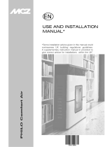
5.4 COMBUSTION AIR
During operation the stove takes in a certain amount
of air from the room where it’s installed (except for
the “Ermetica” series products that can take in air
directly from the outside); this air must be replaced
through an opening to the outside from the room
(Fig. 5.3 - PA = Fresh air vent).
7885
55
85
4
95 4
55
If the wall behind of the stove is an outside wall,
make an opening for drawing in combustion air
dimensions shown on the product data sheet at
the end of this booklet.
A permanent non-closable vent cover must be
placed on the outside of the opening; in especially
windy areas or places exposed to bad weather,
install rain and wind protection elements.
Make sure that the air vent is located in such a
way that it can’t be accidentally obstructed.
If it’s not possible to make a fresh air opening in
the wall behind the stove (not a perimeter wall),
an opening must be made on the wall in the room
where the stove is installed that faces the outside.
If no fresh air opening can be made in the room, it
can be made in an adjacent room as long as the
two rooms are connected by a ventilation grill (Fig.
5.4 - C = Shutter box, G = Grill, S = Shutters)
Standard UNI 10683 prohibits combustion air
being drawn in from garages, combustible material
If there are other heating appliances in the same
room, the fresh air vents must guarantee the
required volume of air for correct operation of all
the appliances.
If one or more exhaust fans (range hoods) are
installed and operating in the room where the
stove is located, combustion problems may occur
due to a lack of combustion air.
C
G
S

38/136 cod. 00 477 2290 - 07/2013 - Palazzetti - PN - Italy
INSTALLATION
“SEALED” SERIES STOVES
The “Ermetica” series pellet stoves allow the
following possible installation alternatives:
ducted combustion air using a coaxial pipe to
consequently no fresh air vent is needed in the
room (Fig. 5.5 A, B=Air intake C, D=Flue gas
outlet);
connect the stove combustion air intake to the
fresh air opening using a special pipe (Fig. 5.6).
5.5 FLUE GAS EXHAUST
The stove operates with negative pressure in the
gas discharge must be airtight.
The stove must be connected to its own
ensuring adequate atmospheric dispersion of the
combustion byproducts.
conditions and bear the CE mark.
have a nominal diameter of 8 cm with gaskets (up
to 5 metres in length), or 10 cm with gaskets (for
lengths exceeding 5 metres) (Fig. 5.7).
rock wool) or made using double wall steel pipes,
except for the initial vertical section inside the
room.
An initial vertical section measuring a minimum of
exhaust.
There should be at least three changes in direction
at the rear of the stove, using 45 or 90° angle
connectors or ‘T’ connectors.
Use always a ‘T’ connector with inspection cap on
It is necessary to connect a pipe at the bottom of the „T“
junction in order to discharge the smoke condensate
The maximum length of horizontal sections is 2-3
connected to:
a chimney used by other heat generators
air exhaust systems (range hoods, vents, etc.....)
even if these are ducted.
Shut-off or draught valves must not be used.
Combustion byproducts must be discharged
through the roof.
B
B
B
Ø 8 cm
Ø 8 cm
Ø 8 cm
MAX 2 - 3 m
C > 3 - 5%
MAX 2 - 3 m
AAD
B
C
Fig. 5.7a

cod. 00 477 2290 - 07/2013 - Palazzetti - PN - Italy 39/136
ENGLISH
INSTALLATION
unsuitable discharge terminal, etc.) flue gas
exhaust may be less than optimum. In these cases,
technical service for this procedure.
“SEALED” SERIES STOVES
For “Ermetica” series pellet stoves a special
gas and duct the combustion air from the outside
(Fig. 5.5 A, B=Air intake C, D=Flue gas outlet).
5.5.1 Discharge through roof using a traditional
chimney
be made in accordance with standards UNI 10683
- EN 1856-1-2 - EN 1857 - EN 1443 - EN 13384-
1-3 - EN 12391-1 both as regards the dimensions
and the construction materials used.
DAMAGED chimneys made from unsuitable
material (asbestos cement, galvanised steel,
etc.... with a rough and porous inside surface)
are prohibited by law and affect proper stove
operation.
traditional chimney (Fig. 5.8) as long as the
following rules are observed:
- check the conditions of the chimney; old chimneys should
be renovated by introducing steel piping with
suitable insulation (rock wool, vermiculite).
only if the latter has a maximum cross-section
of 15 × 15 cm or diameter of 15 cm and features
an inspection opening.
For larger chimneys, suitably insulated steel
pipes need to be inserted on the inside (diameter
according to the length) (Fig. 5.9).
Makes sure connections to brick chimneys are
suitably sealed.
Avoid contact with combustible materials (e.g.
wooden beams).
available on the market.
A) Chimney pot with wind protection
B) Maximum cross-section of 15 × 15 cm or diameter of
15 cm and maximum height of 4- 5 metres
C) Seal
D) Inspection
1) Vermiculite and/or rock wool.
2) Steel pipes.
3) Closure panel.
1
2
3

40/136 cod. 00 477 2290 - 07/2013 - Palazzetti - PN - Italy
INSTALLATION
6 INSTALLATION
in compliance with EN 10683.
6.1 LEVELLING THE STOVE
The stove must be levelled by adjusting the feet
(where featured), then checked using a spirit level
(Fig. 6.1).
A B = Spirit level
6.2 SYSTEM CONNECTIONS
6.2.1 Electrical connection
The stove is connected to the electrical system
simply using the plug supplied.
The electrical connection (plug) must be easily
accessible when the stove is installed.
If the power cord is damaged it must be replaced
to prevent any kind of risk.
6.2.1.1 3
residual current circuit-breaker in accordance with
legislation in force (Fig. 6.2).
6.2.2 Connection to an external timer thermostat
The stove can be connected to an external timer
thermostat that switches the stove on or off
according to the set temperature.
When the set temperature is reached the
thermostat opens the circuit and consequently
switches off the stove.
The external thermostat is connected to the two
terminals on the board of the stove, which are
jumpered in the factory. Disconnect the jumper
and connect the two thermostat contacts.
the instructions shown in the paragraph on “Initial
needs to be switched on manually, while the timer
thermostat is in “call” status. This operation is also
required in the event of power failures or if the stove
is switched off manually.
To avoid overlapping the working time bands, it’s
recommend to disable (set to OFF) the stove’s timer
(see par. 10.1).

cod. 00 477 2290 - 07/2013 - Palazzetti - PN - Italy 41/136
ENGLISH
INSTALLATION
6.3 INITIAL CONFIGURATION
Before proceeding, power up the stove using the safety switch on the rear.
a) Use the arrow buttons to go to the setup menu and then press ;
b) Use the button to select the password “7” and then press
c) Use the buttons to scroll to and select submenu [3 0] ; “ --0
d) Press and enter the value “54” using the buttons;
e) Press
f)
g) buttons;
h) Press
seconds. Ignore this and switch the stove off using the safety switch on the rear, wait a few seconds and
TWO DIFFERENT CONFIGURATIONS ARE AVAILABLE:
CONFIGURATION 1 (default)
The stove will module its power according to the room temperature read by the probe on the stove.
temperature.
CONFIGURATION 2

42/136 cod. 00 477 2290 - 07/2013 - Palazzetti - PN - Italy
USE AND MAINTENANCE
USE AND MAINTENANCE

cod. 00 477 2290 - 07/2013 - Palazzetti - PN - Italy 43/136
ENGLISH
USE AND MAINTENANCE
7 STOVE DESCRIPTION
Before reading this booklet, check the description
of the stove provided in the “Product Booklet”
enclosed.
7.1 CONTROL PANEL
The control panel consists of:
A) a top part with status LEDs and backlit icons
that identify each function;
B) LED display;
C) ON button ;
D) “Cancel” and display “error” button ;
E) two arrow buttons to scroll between the various
functions ;
F) two buttons and to set the operating
parameters and access the submenus;
G) an enter button
the settings.
,
5
4:
7.1.1 Status leds
ICON WARNING DESCRIPTION
Pellets running out
Maintenance Indicates the need to perform maintenance
Service Indicates an error
Remote control receiver It receives the inputs sent by the remote control (optional)
Timer active Indicates whether the timer function is active.
Status LED (near the
button)
LED on steady: stove on and operating
LED off: stove off
C
D
A
B
E
F
G

44/136 cod. 00 477 2290 - 07/2013 - Palazzetti - PN - Italy
USE AND MAINTENANCE
7.1.2 Description of the menus
ICON FUNCTION DESCRIPTION VALUES
Power Stove output setting 1..5
Fan
*(where featured) It allows you to set the fan speed. OFF*,1..5; Auto; Hi
Temperature Displays the room temperature reading and is used to set the desired
temperature. 6°C .. 51°C
Fuel
pellet hopper [FULL], or deactivates the warning [OFF] FULL - OFF
Timer Enables or disables the timer. When enabled, the icon will be
ON - OFF
ICON FUNCTION SUBMENU DESCRIPTION VALUES
Setup
[1 ] Weekly timer Assigns the programs (max 3) to the different days of the
week [d1] ... [d7]
[2] Programs Program setting menu [P1] ... [P6]
[3] Time / date Time and date setting
[4] Hours remaining
Displays the number of hours remaining until recommended
maintenance. When “Hi” is displayed, the remaining time
exceeds 999 hours.
[5] System
information Displays the current software version
[6] Function not enabled
[7] Eco function
Enables or disables Eco Mode, in which the stove
automatically switches off and on based on room temperature
OFF; Eco
[8] Restart delta Difference in degrees from room temperature below which
0,5 ... 5,0°C
[9] Frost protection
temperature
Minimum temperature below which the stove switches on
OFF; 3 ... 20 °C
[1 0] Lock keypad Disables the buttons on the keypad OFF; Lo; Hi
[11] Display brightness Sets display brightness OFF; 1 ... 5
[1 2] Display mode Sets how the data is displayed OFF; 1 ... 4
[13] Buzzer volume Sets the buzzer volume OFF; 1 ... 5
[1 4] Type of pellets Three different types of pellet can be set 1 ... 3
[15] Function not enabled
[3 0] Installer menu Sets/displays the stove configuration PWD: “54”
[4 0] Service menu Menu reserved for the service centre
Submenus [3 0] and [4 0] in the Setup menu are password-protected and reserved for service centre personnel.
7.2 USING THE CONTROL PANEL
The arrow buttons are used to scroll between the different menus that are highlighted.
When selecting a given function, simply press the button and then modify the values, again using the
buttons.
Pressing the
buttons.
The “cancel” button is used to cancel any changes; pressing and holding the button displays any active
alarm or error codes.

cod. 00 477 2290 - 07/2013 - Palazzetti - PN - Italy 45/136
ENGLISH
USE AND MAINTENANCE
7.3 OPERATING PARAMETERS
Stove operation is determined by the Power level, Fan and Temperature parameters set by the user.
7.3.1 setting the power level
consumption.
To change the power level:
a) Use the buttons to go to the power menu and press ;
b) (buttons (1 minimum,....5 maximum)
c) Press
7.3.2 Modifying the fan speed (Silent Range excluded)
To modify the fan speed:
a) Use the buttons to go to the fan menu and press ;
b) The fan speed value will blink; modify the value by pressing ;
“OFF” = the fan is completely excluded, and the stove will work with natural convection only (only on
models where featured);
“1” minimun,..., “5” maximum;
“Auto” = automatic functioning (the stove will set automatically the fan speed and the stove power
according to the room temperature);
“Hi” = ultrarapid functioning (to use only in the case you need to quickly heat the room);
c) press the button
7.3.3 Setting the room temperature
To set the desired temperature:
a) Use the buttons to go to the temperature menu and press ;
b) buttons
c) Press

46/136 cod. 00 477 2290 - 07/2013 - Palazzetti - PN - Italy
USE AND MAINTENANCE
8 PRELIMINARY
OPERATIONS
8.1 LOADING THE PELLETS
The pellets are loaded into in the hopper using a
scoop.
Do not empty the sack directly into the hopper so
as to avoid loading sawdust or other foreign bodies
that may affect proper stove operation and avoid
spilling pellets outside of the hopper.
Make sure the hopper lid is well closed again after
having loaded the pellets. A safety switch (just for
the models that are equipped with it) makes sure
that the pellet tank lid has been closed properly (IS
in
pellet tank lid stays open for more than one minute
while the stove is still working.
At this point, to take advantage of the ‘Autonomy’
function, use the arrow buttons to move to
the combustible icon
. Select “Full” by pressing and press the
button
In order to disable this function, select “Off” instead
of “Full”.
8.2 POWER SUPPLY
Plug the stove into the mains power supply, move
the power switch at the rear of the stove to position
“I” (Fig. 8.2). If the connections are correct the
stove will emit a series of intermittent beeps, the
display will come on.
plugging the stove into the power supply.
If not using the appliance for an extended period,
the switch at the rear of the stove should be moved
to position (O).
8.3 INITIAL SETTINGS
The language, current date and time need to be
set before using the stove.
8.3.1 Time and Date setting
To set the date:
a) Use the buttons to go to the setup menu and press ;
b) Use the button to select the password “7” and then press
c) Use the button to scroll to and select submenu [3] and press
d) buttons and press ;
e) buttons and press ;
f) buttons and press ;
g) buttons and press ;
h) buttons and press ;
i) buttons;
j) Press
IS
Page is loading ...
Page is loading ...
Page is loading ...
Page is loading ...
Page is loading ...
Page is loading ...
Page is loading ...
Page is loading ...
Page is loading ...
Page is loading ...
Page is loading ...
Page is loading ...
-
 1
1
-
 2
2
-
 3
3
-
 4
4
-
 5
5
-
 6
6
-
 7
7
-
 8
8
-
 9
9
-
 10
10
-
 11
11
-
 12
12
-
 13
13
-
 14
14
-
 15
15
-
 16
16
-
 17
17
-
 18
18
-
 19
19
-
 20
20
-
 21
21
-
 22
22
-
 23
23
-
 24
24
-
 25
25
-
 26
26
-
 27
27
-
 28
28
-
 29
29
-
 30
30
-
 31
31
-
 32
32


Palazzetti Ecofire Adagio Installation, User And Maintenance Manual
- Category
- Stoves
- Type
- Installation, User And Maintenance Manual
Ask a question and I''ll find the answer in the document
Finding information in a document is now easier with AI
Related papers
-
Palazzetti ECOFIRE DA INSERIMENTO Installation, User And Maintenance Manual
-
-
-
-
Other documents
-
Royal GLORIA 12 kW Technical Details
-
 MCZ RAAM COMFORT AIR 8 S1 Installation guide
-
 MCZ PHILO COMFORT-AIR Use And Installation Manual
-
Piazzetta P957 Instructions For Installation, Use And Maintenance Manual
-
EdilKamin CHERIE UP Installation, Use And Maintenance Manual
-
-
 MCZ DUO HYDRO-AIR Installation guide
-
 MCZ EGO Use and Maintenance Manual
-
 Jolly Mec STILE Installation, Use And Maintenance Manual
-


