Page is loading ...

EN Installation, use and maintenance page 2
CHERIE UP
PELLET STOVE

2
ENGLISH
The undersigned EDILKAMIN S.p.A., with registered office in
Via Vincenzo Monti 47 - 20123 Milan (Italy) - Tax ID Code and
VAT number 00192220192
Hereby declares, under its sole responsibility, that:
The pellet stove mentioned below complies with EU
Regulation 305/2011 and the harmonised EU standard
EN 14785:2006
PELLET STOVE, trade name EDILKAMIN, model CHERIE UP
SERIAL NO.: Rating plate reference
CHERIE UP: Performance declaration: (DoP - EK No. 043):
Moreover, the company hereby declares that:
the CHERIE UP wood pellet stove satisfies the requirements
of the following European directives:
2014/35/EU - Low Voltage Directive
2014/30/EU - Electromagnetic Compatibility Directive
Introduction and who the manual is for 3
Safety information 4
Dimensions 5
Technical data 6
Unpacking 7
Fitting the cladding Steel 8
Fitting the cladding Ceramic 15
Fitting the cladding Glass 24
Fitting the cladding Stone 29
Installation 33
Instructions for use 38
Maintenance 48
Troubleshooting 51
CONTENTS
USER/INSTALLER
Edition in English translated from the original version in Italian

3
ENGLISH
Dear Sir/Madam
We thank you for and congratulate you on choosing our
product. Before using it, we would ask you to read this
manual carefully, so that you can make the most of all its
functions in total safety.
This manual is an integral part of the product. We ask you
to keep it for the entire lifetime of the product. If you lose it,
you can request a copy from your dealer or download it from
www.edilkamin.com.
Readers of the manual
This manual is addressed to:
• those who use the product at home (“USER”);
• the technician who will install the product (“INSTALLER”)
The target person of each page is indicated in a band at the
bottom of the page (USER or INSTALLER).
General information
After unpacking the product, check the condition and
completeness of the contents.
In the event of error, immediately contact the retailer where
the purchase was made, providing him with a copy of the
warranty booklet and sales receipt.
The appliance must be installed and operated in compliance
with local and national law and European regulations. For the
installation, and for anything not specifically indicated in the
manual, observe local regulations.
The diagrams provided in this manual are for illustration
purposes only: they do not always strictly refer to your
specific model, and are not binding in any way.
MEANING OF SYMBOLS
In some parts of the manual the following symbols are
used:
INFORMATION:
failure to comply with these requirements
will compromise product use.
PLEASE NOTE:
carefully read and understand the
message in question, since failure to
follow the instructions in it could cause
serious damage to the product and put
the safety of those using it at risk.
OPERATING SEQUENCE:
follow the instructions for the operations
described.
Product identification and warranty.
The product is uniquely identified by a number, the
“counterfoil”, which is indicated on the warranty certificate.
Please keep:
• the warranty certificate accompanying the product
• the purchase receipt given to you by the retailer
• the declaration of conformity given to you by the installer.
The warranty conditions are given in the warranty certificate
accompanying the product.
First ignition is required, in Italy, by an authorised
technician in accordance with UNI 10683, and is
recommended in all countries to ensure best results from
the product.
This consists of:
• checking the installation documents (declaration of
conformity) and the quality of the installation itself
• calibrating the product to suit its actual application
• providing explanations to the end user and issuing
the complementary documentation (first ignition -
commissioning certificate)
Having the appliance commissioned properly ensures that it
will operate to best effect and in complete safety.
First ignition is required for activation of the Edilkamin
manufacturer warranty. The warranty is only valid in the
country where the product was bought.
If the appliance is not commissioned by an authorised
technician, Edilkamin will not provide warranty service. See
the warranty booklet for details. The above terms do not
affect the dealer’s legal responsibility for the legal warranty.
The warranty, however, covers only demonstrable
manufacturing defects and not, for instance, problems
resulting from improper installation or calibration.
USER/INSTALLER

4
ENGLISH
SAFETY INFORMATION
• The product is not designed for use by people,
including children, with limited physical, sensory
and mental abilities.
• The appliance is not designed for cooking
purposes.
• The appliance is designed to burn UNI EN ISO
17225-2 category A1 wood pellets, in the amounts
and manner described in this manual.
• The appliance is designed for indoor use and in
areas with normal humidity conditions.
• Keep the product in a dry place out of the weather.
• For the legal and company warranties, refer to the
warranty certificate inside the product: specifically,
neither Edilkamin nor the retailer are liable for
damage resulting from incorrect installation or
maintenance.
Safety risks may be caused by:
• Installation in non-suitable settings, in particular
those that are subject to fire risks. DO NOT
INSTALL THE PRODUCT IN AREAS SUBJECT TO
THE RISK OF FIRE.
• Contact with fire and hot parts (e.g. glass panel
and pipes). DO NOT TOUCH HOT PARTS and,
when the stove is switched off and still hot, always
wear the glove supplied.
• Contact with live electrical equipment (internal).
DO NOT ACCESS THE INTERNAL ELECTRICAL
EQUIPMENT WHILE THE APPLIANCE IS
POWERED ON. Electrocution hazard.
• Use of improper ignition aids (e.g. alcohol). DO
NOT IGNITE OR BOOST THE FLAME WITH FLUID
SPRAYS OR A FLAME TORCH. Serious risk of
burns, damage and injury.
• Use of fuel other than wood pellets. DO NOT BURN
WASTE MATTER, PLASTIC OR MATERIALS OTHER
THAN WOOD PELLETS IN THE COMBUSTION
CHAMBER. The product may become soiled, the
flue may catch fire, and environmental damage
may ensue.
• Cleaning the combustion chamber when hot. DO
NOT CLEAN WITH A VACUUM CLEANER WHEN
HOT. You could damage the vacuum-cleaner and
risk the emission of smoke in the room.
• Cleaning the smoke duct with cleaning products.
DO NOT CLEAN THE PRODUCT WITH
FLAMMABLE PRODUCTS. Risk of fire or blowback.
• Cleaning the glass pane while hot or with unsuitable
cleaning products. DO NOT CLEAN HOT GLASS
WITH WATER. ONLY USE RECOMMENDED
GLASS CLEANING PRODUCTS. Risk of cracking
and permanent, irreparable damage to the glass.
• The storage of flammable materials at a distance
which is less than the safe distances listed in
this manual. DO NOT PLACE LAUNDRY ON
THE APPLIANCE. DO NOT PLACE DRYING
RACKS WITHIN THE SAFETY CLEARANCE. Keep
flammable fluids away from the appliance. Fire
hazard.
• Blocking the aeration vents and air intakes in the
room. DO NOT BLOCK THE AERATION VENTS
OR FLUE. Risk of smoke returning into the room
with consequent damage and injury.
• Use of the product as a support or ladder. DO
NOT CLIMB ONTO THE PRODUCT OR USE IT AS
A SUPPORT. Risk of damage and injury.
• Use of the stove with the combustion chamber
open. DO NOT USE THE PRODUCT WITH ITS
DOOR OPEN.
• Incandescent material may come out from the
open door. DO NOT throw incandescent material
outside the appliance. Fire hazard.
• Use of water in case of fire. CALL THE
AUTHORITIES if a fire breaks out.
• If you have doubts, please do not take any action,
but contact the retailer or the installer.
For reasons of safety, read the user instructions
included in this manual.
USER/INSTALLER

5
ENGLISH
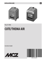
DIMENSIONS
DIMENSIONS (cm)
USER/INSTALLER
57
62
115
115
57
33
101,5
9
Ø 4 cm
combustion air
Ø 8 cm
hot air ducting *
18,5
25
18,5
31 10 21
Ø 8 cm
smoke
outlet
* accessories for ducting hot air are available

6
ENGLISH
The above data is for guidance only and was measured during certification by a notified body.
EDILKAMIN s.p.a. reserves the right to modify the product without notification in the interests of improvement.
ELECTRICAL SPECIFICATIONS
Power supply 230 V AC +/- 10% 50 Hz
Mean absorbed power 50 - 80 W
Power absorption during ignition 300 W
Remote control frequency (provided) 2.4 GHz
Protection rating Fuse 4 AT 250 V AC 5x20
TECHNICAL DATA
USER/INSTALLER
TECHNICAL CHARACTERISTICS in accordance with EN 14785
The above data is for guidance only and was taken during the certification phase by a notified body under the
conditions specified by the standard.
CHERIE UP
Nominal power Reduced power
Available power 11,2 5,5 kW
Efficiency 90,0 93,3 %
CO emissions at 13% O
2
0,016 0,044 %
Fumes temperature 179 109 °C
Fuel consumption 2,5 1,2 kg/h
Tank capacity 26 kg
Draw 12 10 Pa
Autonomy 10 22 hours
Heatable volume * 285 m
3
Fumes outlet diameter (male) 80 mm
Air intake diameter (male) 40 mm
Ducting diameter 80 mm
Weight with packaging (steel/ceramic/glass/
stone)
214/230/207/271 kg
Energy efficiency classes
(2015-1186/1187 Regulation)
A+
TECHNICAL DATA FOR RATING THE FLUE
which must in any case satisfy the requirements of this sheet and the installation instructions
Nominal power Reduced power
Fumes temperature at smoke outlet 215 130 °C
Minimum draw 0.01 Pa
Fumes flow rate 7.25 4.31 Rps

7
ENGLISH
UNPACKING
INSTALLER
ADJUSTABLE FEET
The stoves have four adjustable feet to adapt to
uneven floors.
They can be adjusted by lifting the boiler stove slightly..
In order to obtain a correct cooling air flow, please
make sure feet will be at least one square cm. high
PREPARATION AND UNPACKING
The packaging materials are neither toxic nor noxious
and do not require special disposal. The user is
responsible for storing, disposing of and recycling
them in a regulatory fashion.
PACKAGING
CHERIE UP STEEL
One package containing:
• the stove structure
• the box with the steel side panels
• the box with the bottom front panel, brackets and
small parts
• the box with the cast iron top
CHERIE UP CERAMIC
One package containing:
• the stove structure
• the box with the ceramic side panels
• the box with the bottom front panel, brackets and
small parts
• the box with the ceramic top
CHERIE UP GLASS
One package containing:
• the stove structure
• the box with the glass side panels
• the box with the bottom front panel, brackets and
small parts
• the box with the cast iron top
CHERIE UP STONE
One package containing:
• the stove structure
• the box with the side panels
• the box with the bottom front panel
• the box with the cast iron top
The product contains: the warranty certificate, the
glove, this manual, the power supply cable, the
device for activating the cleaning system (see the
“Maintenance” paragraph). The lever for opening the
door is on the pallet.
Carry out all movements in a vertical
position, using appropriate means.
Be careful to follow all relevant safety
regulations.
Take care not to tip the product over.
TO REMOVE THE PALLET (ALL MODELS)
The stove is secured to the pallet with four brackets:
two at the front and two at the back.
Undo the two screws on each bracket.

8
ENGLISH
STEEL CLADDING
As indicated in the “Packaging” section, the steel cladding parts are contained in three separate boxes
• the box with the steel side panels
• the box with the bottom front panel, brackets and small parts
• the box with the cast iron top
2
1
1
2
5
box with the steel side panels
box with the cast iron top
box with the bottom front panel, brackets and small parts
3
4
INSTALLER
keep this for the assembly of the cladding

9
ENGLISH
Description
Reference in
Figures
Quantity
Side panel (bottom right or top left) (1) 2
Side panel (bottom left or top right) (2) 2
Brackets for fitting the side panels
and small parts
(3) brackets for the side panels (2 per side panel)
washers, nuts, M5 screws 4 M5 toothed washers for side
panels
20 M6 screws and M6 toothed washers for front panel
Bottom front panel (4) 1
Cast iron top (5) 1
1. Remove the pellet tank cover
Loosen the wing screws underneath and remove the pellet tank cover by pulling it towards the front. This will
subsequently enable you to position the top and screw on the side panels.
2. Assembling and fitting the side panels onto the structure
On each of the sides, undo the metal support screws, unhook the metal support and remove it.
wing screws
screws for fitting the metal supports
metal
support
STEEL CLADDING
INSTALLER

10
ENGLISH
STEEL CLADDING
To assemble the two sides, we recommend that you place them on the shaped polystyrene piece and proceed as
follows
screw
washer
nut
INSTALLER
central spacer
1
1
1. bring the side panels together, place the central spacer and screw them together (1);
shaped polystyrene piece
NOTE. The curving of the side panels may not perfectly coincide with the curving of the brackets. Therefore, use your
hands to make the panel fit to the bracket before tightening the screws. Do not use any tools so as to avoid the risk
of scratching the side panel. Once the position of the side panel is correct, tighten the screws while keeping the side
panel in position. This will also avoid any interference with the door.

11
ENGLISH
STEEL CLADDING
2. Place the brackets. Tighten the screws and also insert the nuts and washers above and underneath, only on one
side.
NOTE For a better understanding of the position, the image below shows the components in a vertical position, but
we nevertheless recommend that you work in a horizontal position on top of the shaped polystyrene piece.
INSTALLER
screw
nut
bracket
bracket
nut
screw
black toothed washer
toothed washer
black toothed washer
toothed washer

12
ENGLISH
washer
nut
toothed washer
STEEL CLADDING
3. position the metal support. Tighten the screws and also insert the nuts and washers above and underneath, only
on one side.
INSTALLER
NOTE. The curving of the side panels may not perfectly coincide with the
curving of the brackets. Therefore, use your hands to make the panel fit
to the bracket before tightening the screws (V). Do not use any tools so
as to avoid the risk of scratching the side panel. Once the position of the
side panel is correct, tighten the screws while keeping the side panel in
position. This will also avoid any interference with the door.
(V)
(V)
(V)
Make sure that the central spacer has been placed
in the “cut” on the metal support.
central spacer
“cut” on the metal support

13
ENGLISH
Then hook the assembled side panel with the metal support to the structure (inside the slots) and re-tighten the
screws securing the metal supports
STEEL CLADDING
screws for fitting the metal supports
INSTALLER
3. Fitting of the bottom front panel
Open the combustion chamber door using the removable handle. Hook the bottom front panel (4 hooks, two per side)
and fasten it with the M6 Allen screw and the toothed washer.
fasten it with the M6
Allen screw and the
toothed washer

14
ENGLISH
4. Fitting the top
Place the top by slotting it onto the two pins.
Put the pellet tank cover back on, by tightening the wing screws removed at point 1.
STEEL CLADDING
INSTALLER

15
ENGLISH
shaped
polystyrene piece:
keep this for
when you fit the
cladding
CERAMIC CLADDING
4
f
c
g
h
i l
a
b
d
m
e
As indicated in the “Packaging” section, the ceramic cladding parts are contained in three separate boxes
• box with the ceramic side panels
• box with the bottom front panel, brackets and small parts
• box with the ceramic top
2
1
5
box with the ceramic side panels
box with the ceramic top
box with the bottom front panel, brackets and small parts
3
Description Reference in
the figures
Quantity
Side panel (bottom right or top left) (1) 2
Side panel (bottom left or top right) (2) 2
Brackets for fitting the side panels Small
parts
(3) see detail in inset figure
Bottom front panel (4) 1
Ceramic top (5) 1
INSTALLER

16
ENGLISH
CERAMIC CLADDING
Description Reference in
the figures
Quantity Notes
Washer D5 a 20 For side panels and front panel
Screw TE M4x10 b 20 For side panels and front panel
Adjustment bracket c 2 For side panels
Screw 4.2x9.5 d 10 For side panels at the top and bottom for small
bracket (h)
Rubber item screw M6 e 4 For top panel
Screw M4x20 f 2 On side panels
Cage Nut M4 g 2 On side panels
Small adjustment bracket h 2 On side panels
Right bracket for bottom
front panel
i 1 For bottom front panel
Left bracket for bottom front
panel
l 1 For bottom front panel
Screw M6x20 m 5 For front panel and top
Template n 1 For correct positioning of ceramic side panels
INSTALLER
f
c
g
h
i l
a
b
d
m
e
n

17
ENGLISH
1. Remove the pellet tank cover
Loosen the wing screws underneath and remove the pellet tank cover by pulling it towards the front. This will
subsequently enable you to position the top and screw on the side panels
2. Assembling and fitting the side panels onto the structure
On each of the sides, undo the metal support screws, unhook the metal support and remove it.
wing screws
screws for fitting the metal supports
metal
support
CERAMIC CLADDING
INSTALLER

18
ENGLISH
CERAMIC CLADDING
To assemble the two sides, we recommend that you place them on the shaped polystyrene piece and proceed as follows
INSTALLER
2
1
Bring the ceramic side panels together (1)
shaped polystyrene piece
Position the two adjustment brackets on the ceramic piece and apply the screws without tightening them
adjustment bracket (c)
adjustment bracket (c)
screw TE M4x10 (b)
washer
D5 (a)

19
ENGLISH
CERAMIC CLADDING
INSTALLER
Once the metal support has been assembled with the small bracket, place it on the ceramic pieces and apply the
screws and washers but without tightening, as shown in the figure below.
The correct position is the point where the bracket profile meets with the
metal support. Tighten the screws that fix the brackets to the metal profile
*
metal support
Position the small bracket with the cage nut on the metal support and screw on with the supplied M4.2x9.5 screw.
The drawing shows the left side panel (for the location of the small adjustment bracket).
metal
support
screw TE M4x10 (b)
washer D5 (a)
Screw .4.2x9.5 (d)
*

20
ENGLISH
Before tightening the screws, for each of the two ceramic pieces (above and below):
position the template for fitting the side panels;
Respect the distances between the metal support and the ceramic piece as in the drawing (60 and 70 mm). The
70 mm measurement can also be taken from the template position
CERAMIC CLADDING
INSTALLER
template
Do not force the screw into the threaded bushing -
it may break.
reference measurement
reference measurement
reference measurement
1/56