STMicroelectronics STSW-STM32122 User manual
- Category
- Sport watches
- Type
- User manual
This manual is also suitable for

May 2012 Doc ID 022862 Rev 1 1/66
UM1520
User manual
STM320518-EVAL demonstration firmware
Introduction
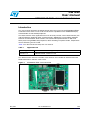
This user manual describes the demonstration firmware running on the STM320518-EVAL
evaluation board, which can be used to evaluate the capabilities of the STM32F0518(T6)
microcontroller and on-board peripherals.
This demo contains many applications that can be easily reused, such as dual interface (I2C
and RF) EEprom application (ESL and DataLogger), HDMI-CEC, Infrared RC5 and SIRC
Receiver and Transmitter, RTC calendar, File system FAT implementation on SD Card,
Wave player using STM32 DAC peripheral, Voice recording, low power modes, Temperature
sensor interfacing and TFT LCD.
Table 1 lists the tool concerned by this user manual.
This demonstration firmware and other such firmware are available for download from the
STMicroelectronics website: www.st.com.
Figure 1. STM320518-EVAL evaluation board
Table 1. Applicable tool
Type Applicable products
Evaluation tool STM320518-EVAL evaluation board
www.st.com

Contents UM1520
2/66 Doc ID 022862 Rev 1
Contents
1 Functional description . . . . . . . . . . . . . . . . . . . . . . . . . . . . . . . . . . . . . . . 6
1.1 Power control . . . . . . . . . . . . . . . . . . . . . . . . . . . . . . . . . . . . . . . . . . . . . . . 7
1.2 Clocking . . . . . . . . . . . . . . . . . . . . . . . . . . . . . . . . . . . . . . . . . . . . . . . . . . . 7
1.3 Reset control . . . . . . . . . . . . . . . . . . . . . . . . . . . . . . . . . . . . . . . . . . . . . . . 7
1.4 Debug JTAG interface . . . . . . . . . . . . . . . . . . . . . . . . . . . . . . . . . . . . . . . . 7
1.5 Serial wire debugger interface . . . . . . . . . . . . . . . . . . . . . . . . . . . . . . . . . . 7
1.6 Embedded ST-LINK/V2 . . . . . . . . . . . . . . . . . . . . . . . . . . . . . . . . . . . . . . . 7
1.7 Display devices . . . . . . . . . . . . . . . . . . . . . . . . . . . . . . . . . . . . . . . . . . . . . . 7
1.7.1 LCD . . . . . . . . . . . . . . . . . . . . . . . . . . . . . . . . . . . . . . . . . . . . . . . . . . . . . 7
1.7.2 LEDs . . . . . . . . . . . . . . . . . . . . . . . . . . . . . . . . . . . . . . . . . . . . . . . . . . . . 7
1.7.3 LDR (Light Dependent Resistor) . . . . . . . . . . . . . . . . . . . . . . . . . . . . . . . 8
1.8 Interfaces . . . . . . . . . . . . . . . . . . . . . . . . . . . . . . . . . . . . . . . . . . . . . . . . . . 8
1.8.1 RS232 and RS485 . . . . . . . . . . . . . . . . . . . . . . . . . . . . . . . . . . . . . . . . . 8
1.9 IrDA . . . . . . . . . . . . . . . . . . . . . . . . . . . . . . . . . . . . . . . . . . . . . . . . . . . . . . 8
1.10 Miscellaneous peripherals . . . . . . . . . . . . . . . . . . . . . . . . . . . . . . . . . . . . . 8
1.10.1 Joystick . . . . . . . . . . . . . . . . . . . . . . . . . . . . . . . . . . . . . . . . . . . . . . . . . . 8
1.10.2 Push-buttons . . . . . . . . . . . . . . . . . . . . . . . . . . . . . . . . . . . . . . . . . . . . . . 8
1.10.3 12-bit analog-to-digital converter (ADC) . . . . . . . . . . . . . . . . . . . . . . . . . 8
1.10.4 Audio . . . . . . . . . . . . . . . . . . . . . . . . . . . . . . . . . . . . . . . . . . . . . . . . . . . . 8
1.10.5 MicroSD card . . . . . . . . . . . . . . . . . . . . . . . . . . . . . . . . . . . . . . . . . . . . . . 8
1.10.6 Serial EEPROM . . . . . . . . . . . . . . . . . . . . . . . . . . . . . . . . . . . . . . . . . . . . 9
1.10.7 RF EEPROM . . . . . . . . . . . . . . . . . . . . . . . . . . . . . . . . . . . . . . . . . . . . . . 9
1.10.8 IR LED and IR receiver . . . . . . . . . . . . . . . . . . . . . . . . . . . . . . . . . . . . . . 9
1.10.9 HDMI CEC . . . . . . . . . . . . . . . . . . . . . . . . . . . . . . . . . . . . . . . . . . . . . . . . 9
1.10.10 Temperature sensor . . . . . . . . . . . . . . . . . . . . . . . . . . . . . . . . . . . . . . . . . 9
1.10.11 Touch slider . . . . . . . . . . . . . . . . . . . . . . . . . . . . . . . . . . . . . . . . . . . . . . . 9
1.10.12 STM320518-EVAL board jumper configuration . . . . . . . . . . . . . . . . . . . . 9
2 Running the demonstration . . . . . . . . . . . . . . . . . . . . . . . . . . . . . . . . . . 10
2.1 Menu . . . . . . . . . . . . . . . . . . . . . . . . . . . . . . . . . . . . . . . . . . . . . . . . . . . . 10
2.1.1 Demo startup . . . . . . . . . . . . . . . . . . . . . . . . . . . . . . . . . . . . . . . . . . . . . 12
2.1.2 Navigation . . . . . . . . . . . . . . . . . . . . . . . . . . . . . . . . . . . . . . . . . . . . . . . 16
2.2 Clock sources . . . . . . . . . . . . . . . . . . . . . . . . . . . . . . . . . . . . . . . . . . . . . . 17

UM1520 Contents
Doc ID 022862 Rev 1 3/66
2.2.1 Clock control . . . . . . . . . . . . . . . . . . . . . . . . . . . . . . . . . . . . . . . . . . . . . 17
2.2.2 Clock failure . . . . . . . . . . . . . . . . . . . . . . . . . . . . . . . . . . . . . . . . . . . . . . 18
2.3 STM32F051R8(T6) resources . . . . . . . . . . . . . . . . . . . . . . . . . . . . . . . . . 19
2.3.1 Peripherals . . . . . . . . . . . . . . . . . . . . . . . . . . . . . . . . . . . . . . . . . . . . . . . 19
2.3.2 Interrupts . . . . . . . . . . . . . . . . . . . . . . . . . . . . . . . . . . . . . . . . . . . . . . . . 20
2.3.3 External interrupts . . . . . . . . . . . . . . . . . . . . . . . . . . . . . . . . . . . . . . . . . 20
2.3.4 Internal memory size . . . . . . . . . . . . . . . . . . . . . . . . . . . . . . . . . . . . . . . 21
2.3.5 External memory organization . . . . . . . . . . . . . . . . . . . . . . . . . . . . . . . . 21
2.4 Demo applications . . . . . . . . . . . . . . . . . . . . . . . . . . . . . . . . . . . . . . . . . . 22
2.4.1 Calendar . . . . . . . . . . . . . . . . . . . . . . . . . . . . . . . . . . . . . . . . . . . . . . . . 22
2.4.2 Image Viewer submenu . . . . . . . . . . . . . . . . . . . . . . . . . . . . . . . . . . . . . 27
2.4.3 Wave Player submenu . . . . . . . . . . . . . . . . . . . . . . . . . . . . . . . . . . . . . . 28
2.4.4 Wave Record . . . . . . . . . . . . . . . . . . . . . . . . . . . . . . . . . . . . . . . . . . . . . 31
2.4.5 Low-power modes . . . . . . . . . . . . . . . . . . . . . . . . . . . . . . . . . . . . . . . . . 33
2.4.6 Thermometer . . . . . . . . . . . . . . . . . . . . . . . . . . . . . . . . . . . . . . . . . . . . . 40
2.4.7 HDMI™ CEC submenu . . . . . . . . . . . . . . . . . . . . . . . . . . . . . . . . . . . . . 42
2.4.8 Dual interface EEPROM (RF/I²C) . . . . . . . . . . . . . . . . . . . . . . . . . . . . . 45
2.4.9 Applications . . . . . . . . . . . . . . . . . . . . . . . . . . . . . . . . . . . . . . . . . . . . . . 50
2.4.10 InfraRed . . . . . . . . . . . . . . . . . . . . . . . . . . . . . . . . . . . . . . . . . . . . . . . . . 53
2.4.11 Help . . . . . . . . . . . . . . . . . . . . . . . . . . . . . . . . . . . . . . . . . . . . . . . . . . . . 57
2.4.12 About submenu . . . . . . . . . . . . . . . . . . . . . . . . . . . . . . . . . . . . . . . . . . . 61
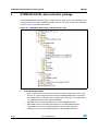
3 STM320518-EVAL demonstration package . . . . . . . . . . . . . . . . . . . . . . 62
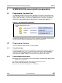
4 STM320518-EVAL demonstration programming . . . . . . . . . . . . . . . . . 64
4.1 Programming the media files . . . . . . . . . . . . . . . . . . . . . . . . . . . . . . . . . . 64
4.2 Programming the demo . . . . . . . . . . . . . . . . . . . . . . . . . . . . . . . . . . . . . . 64
4.2.1 Using Bootloader . . . . . . . . . . . . . . . . . . . . . . . . . . . . . . . . . . . . . . . . . . 64
4.2.2 Using preconfigured projects . . . . . . . . . . . . . . . . . . . . . . . . . . . . . . . . . 64
5 Revision history . . . . . . . . . . . . . . . . . . . . . . . . . . . . . . . . . . . . . . . . . . . 65

List of figures UM1520
4/66 Doc ID 022862 Rev 1
List of figures
Figure 1. STM320518-EVAL evaluation board . . . . . . . . . . . . . . . . . . . . . . . . . . . . . . . . . . . . . . . . . . 1
Figure 2. Evaluation board overview . . . . . . . . . . . . . . . . . . . . . . . . . . . . . . . . . . . . . . . . . . . . . . . . . . 6
Figure 3. Structure of the demonstration config1 menus . . . . . . . . . . . . . . . . . . . . . . . . . . . . . . . . . . 11
Figure 4. Structure of the demonstration config2 menus . . . . . . . . . . . . . . . . . . . . . . . . . . . . . . . . . . 12
Figure 5. SD card check . . . . . . . . . . . . . . . . . . . . . . . . . . . . . . . . . . . . . . . . . . . . . . . . . . . . . . . . . . 13
Figure 6. Warning message. . . . . . . . . . . . . . . . . . . . . . . . . . . . . . . . . . . . . . . . . . . . . . . . . . . . . . . . 13
Figure 7. ST logo . . . . . . . . . . . . . . . . . . . . . . . . . . . . . . . . . . . . . . . . . . . . . . . . . . . . . . . . . . . . . . . . 14
Figure 8. Time and date configuration . . . . . . . . . . . . . . . . . . . . . . . . . . . . . . . . . . . . . . . . . . . . . . . . 14
Figure 9. Main menu config1 . . . . . . . . . . . . . . . . . . . . . . . . . . . . . . . . . . . . . . . . . . . . . . . . . . . . . . . 15
Figure 10. Main menu config2 . . . . . . . . . . . . . . . . . . . . . . . . . . . . . . . . . . . . . . . . . . . . . . . . . . . . . . . 15
Figure 11. Corresponding submenus. . . . . . . . . . . . . . . . . . . . . . . . . . . . . . . . . . . . . . . . . . . . . . . . . . 16
Figure 12. Navigating in the demonstration menus . . . . . . . . . . . . . . . . . . . . . . . . . . . . . . . . . . . . . . . 16
Figure 13. Clock tree diagram . . . . . . . . . . . . . . . . . . . . . . . . . . . . . . . . . . . . . . . . . . . . . . . . . . . . . . . 17
Figure 14. No HSE clock detected. . . . . . . . . . . . . . . . . . . . . . . . . . . . . . . . . . . . . . . . . . . . . . . . . . . . 18
Figure 15. Standby mode entered . . . . . . . . . . . . . . . . . . . . . . . . . . . . . . . . . . . . . . . . . . . . . . . . . . . . 18
Figure 16. Internal Flash memory organization . . . . . . . . . . . . . . . . . . . . . . . . . . . . . . . . . . . . . . . . . . 21
Figure 17. SD card removal . . . . . . . . . . . . . . . . . . . . . . . . . . . . . . . . . . . . . . . . . . . . . . . . . . . . . . . . . 22
Figure 18. Setting the time and date . . . . . . . . . . . . . . . . . . . . . . . . . . . . . . . . . . . . . . . . . . . . . . . . . . 22
Figure 19. Time Adjust submenu . . . . . . . . . . . . . . . . . . . . . . . . . . . . . . . . . . . . . . . . . . . . . . . . . . . . . 23
Figure 20. Time Show submenu . . . . . . . . . . . . . . . . . . . . . . . . . . . . . . . . . . . . . . . . . . . . . . . . . . . . . 23
Figure 21. Setting the year. . . . . . . . . . . . . . . . . . . . . . . . . . . . . . . . . . . . . . . . . . . . . . . . . . . . . . . . . . 24
Figure 22. Setting the month . . . . . . . . . . . . . . . . . . . . . . . . . . . . . . . . . . . . . . . . . . . . . . . . . . . . . . . . 25
Figure 23. Setting the day of the month. . . . . . . . . . . . . . . . . . . . . . . . . . . . . . . . . . . . . . . . . . . . . . . . 25
Figure 24. Exiting the Date Show submenu. . . . . . . . . . . . . . . . . . . . . . . . . . . . . . . . . . . . . . . . . . . . . 26
Figure 25. Setting the alarm activation time. . . . . . . . . . . . . . . . . . . . . . . . . . . . . . . . . . . . . . . . . . . . . 26
Figure 26. Alarm Show submenu. . . . . . . . . . . . . . . . . . . . . . . . . . . . . . . . . . . . . . . . . . . . . . . . . . . . . 27
Figure 27. Message displayed if time and date need setting. . . . . . . . . . . . . . . . . . . . . . . . . . . . . . . . 27
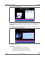
Figure 28. Image Viewer submenu . . . . . . . . . . . . . . . . . . . . . . . . . . . . . . . . . . . . . . . . . . . . . . . . . . . 28
Figure 29. STM32 Image Viewer . . . . . . . . . . . . . . . . . . . . . . . . . . . . . . . . . . . . . . . . . . . . . . . . . . . . . 28
Figure 30. Wave Player submenu . . . . . . . . . . . . . . . . . . . . . . . . . . . . . . . . . . . . . . . . . . . . . . . . . . . . 29
Figure 31. Wave Player interface. . . . . . . . . . . . . . . . . . . . . . . . . . . . . . . . . . . . . . . . . . . . . . . . . . . . . 30
Figure 32. Wave Player Playing submenu. . . . . . . . . . . . . . . . . . . . . . . . . . . . . . . . . . . . . . . . . . . . . . 30
Figure 33. Pause submenu . . . . . . . . . . . . . . . . . . . . . . . . . . . . . . . . . . . . . . . . . . . . . . . . . . . . . . . . . 31
Figure 34. Voice Recording submenu selected . . . . . . . . . . . . . . . . . . . . . . . . . . . . . . . . . . . . . . . . . . 32
Figure 35. Record submenu . . . . . . . . . . . . . . . . . . . . . . . . . . . . . . . . . . . . . . . . . . . . . . . . . . . . . . . . 32
Figure 36. Starting wave record. . . . . . . . . . . . . . . . . . . . . . . . . . . . . . . . . . . . . . . . . . . . . . . . . . . . . . 33
Figure 37. Exiting the Stop mode. . . . . . . . . . . . . . . . . . . . . . . . . . . . . . . . . . . . . . . . . . . . . . . . . . . . . 34
Figure 38. Stop mode entered exit EXTI . . . . . . . . . . . . . . . . . . . . . . . . . . . . . . . . . . . . . . . . . . . . . . . 34
Figure 39. MCU in the Stop mode Exit EXTI . . . . . . . . . . . . . . . . . . . . . . . . . . . . . . . . . . . . . . . . . . . . 35
Figure 40. RTC Alarm causes the MCU to exit the Stop mode . . . . . . . . . . . . . . . . . . . . . . . . . . . . . . 35
Figure 41. Setting the Wakeup time. . . . . . . . . . . . . . . . . . . . . . . . . . . . . . . . . . . . . . . . . . . . . . . . . . . 36
Figure 42. RTC Alarm wakeup configured. . . . . . . . . . . . . . . . . . . . . . . . . . . . . . . . . . . . . . . . . . . . . . 36
Figure 43. RTC Alarm wakeup. . . . . . . . . . . . . . . . . . . . . . . . . . . . . . . . . . . . . . . . . . . . . . . . . . . . . . . 36
Figure 44. Time and Date configuration prompt . . . . . . . . . . . . . . . . . . . . . . . . . . . . . . . . . . . . . . . . . 37
Figure 45. Entering the Standby mode . . . . . . . . . . . . . . . . . . . . . . . . . . . . . . . . . . . . . . . . . . . . . . . . 37
Figure 46. MCU in Standby mode . . . . . . . . . . . . . . . . . . . . . . . . . . . . . . . . . . . . . . . . . . . . . . . . . . . . 38
Figure 47. RTC Alarm causes the MCU to exit the Standby mode . . . . . . . . . . . . . . . . . . . . . . . . . . . 38
Figure 48. Setting the wakeup time . . . . . . . . . . . . . . . . . . . . . . . . . . . . . . . . . . . . . . . . . . . . . . . . . . . 39

UM1520 List of figures
Doc ID 022862 Rev 1 5/66
Figure 49. RTC Alarm wakeup configured. . . . . . . . . . . . . . . . . . . . . . . . . . . . . . . . . . . . . . . . . . . . . . 39
Figure 50. Time and Date configuration prompt . . . . . . . . . . . . . . . . . . . . . . . . . . . . . . . . . . . . . . . . . 40
Figure 51. Thermometer submenu selected . . . . . . . . . . . . . . . . . . . . . . . . . . . . . . . . . . . . . . . . . . . . 40
Figure 52. Temperature display . . . . . . . . . . . . . . . . . . . . . . . . . . . . . . . . . . . . . . . . . . . . . . . . . . . . . . 41
Figure 53. Warning temperature display . . . . . . . . . . . . . . . . . . . . . . . . . . . . . . . . . . . . . . . . . . . . . . . 41
Figure 54. Temperature sensor error. . . . . . . . . . . . . . . . . . . . . . . . . . . . . . . . . . . . . . . . . . . . . . . . . . 42
Figure 55. HDMI CEC submenu selected . . . . . . . . . . . . . . . . . . . . . . . . . . . . . . . . . . . . . . . . . . . . . . 42
Figure 56. HDMI CEC configuration submenu. . . . . . . . . . . . . . . . . . . . . . . . . . . . . . . . . . . . . . . . . . . 43
Figure 57. CEC menu . . . . . . . . . . . . . . . . . . . . . . . . . . . . . . . . . . . . . . . . . . . . . . . . . . . . . . . . . . . . . 43
Figure 58. Select CEC command . . . . . . . . . . . . . . . . . . . . . . . . . . . . . . . . . . . . . . . . . . . . . . . . . . . . 44
Figure 59. Receive subscreen information . . . . . . . . . . . . . . . . . . . . . . . . . . . . . . . . . . . . . . . . . . . . . 44
Figure 60. ANT7-M24LR-A dual interface EEPROM daughter board . . . . . . . . . . . . . . . . . . . . . . . . . 45
Figure 61. M24LR64-R block diagram . . . . . . . . . . . . . . . . . . . . . . . . . . . . . . . . . . . . . . . . . . . . . . . . . 45
Figure 62. Dual Interface EEPROM applications menu. . . . . . . . . . . . . . . . . . . . . . . . . . . . . . . . . . . . 46
Figure 63. ESL application. . . . . . . . . . . . . . . . . . . . . . . . . . . . . . . . . . . . . . . . . . . . . . . . . . . . . . . . . . 46
Figure 64. ESL setting menu . . . . . . . . . . . . . . . . . . . . . . . . . . . . . . . . . . . . . . . . . . . . . . . . . . . . . . . . 47
Figure 65. DataLogger block diagram . . . . . . . . . . . . . . . . . . . . . . . . . . . . . . . . . . . . . . . . . . . . . . . . . 48
Figure 66. DataLogger dialog box . . . . . . . . . . . . . . . . . . . . . . . . . . . . . . . . . . . . . . . . . . . . . . . . . . . . 49
Figure 67. DataLogger curve . . . . . . . . . . . . . . . . . . . . . . . . . . . . . . . . . . . . . . . . . . . . . . . . . . . . . . . . 50
Figure 68. Applications menu . . . . . . . . . . . . . . . . . . . . . . . . . . . . . . . . . . . . . . . . . . . . . . . . . . . . . . . 51
Figure 69. StopWatch submenu . . . . . . . . . . . . . . . . . . . . . . . . . . . . . . . . . . . . . . . . . . . . . . . . . . . . . 51
Figure 70. Timer submenu. . . . . . . . . . . . . . . . . . . . . . . . . . . . . . . . . . . . . . . . . . . . . . . . . . . . . . . . . . 52
Figure 71. Light Intensity Level . . . . . . . . . . . . . . . . . . . . . . . . . . . . . . . . . . . . . . . . . . . . . . . . . . . . . . 53
Figure 72. InfraRed menu . . . . . . . . . . . . . . . . . . . . . . . . . . . . . . . . . . . . . . . . . . . . . . . . . . . . . . . . . . 54
Figure 73. IR Transmitter menu . . . . . . . . . . . . . . . . . . . . . . . . . . . . . . . . . . . . . . . . . . . . . . . . . . . . . . 54
Figure 74. IR transmitter command menu . . . . . . . . . . . . . . . . . . . . . . . . . . . . . . . . . . . . . . . . . . . . . . 55
Figure 75. IR receiver menu . . . . . . . . . . . . . . . . . . . . . . . . . . . . . . . . . . . . . . . . . . . . . . . . . . . . . . . . 55
Figure 76. IR receiver application menu . . . . . . . . . . . . . . . . . . . . . . . . . . . . . . . . . . . . . . . . . . . . . . . 56
Figure 77. IR receiver command menu . . . . . . . . . . . . . . . . . . . . . . . . . . . . . . . . . . . . . . . . . . . . . . . . 56
Figure 78. Help menu . . . . . . . . . . . . . . . . . . . . . . . . . . . . . . . . . . . . . . . . . . . . . . . . . . . . . . . . . . . . . 57
Figure 79. Navigation menu-1 . . . . . . . . . . . . . . . . . . . . . . . . . . . . . . . . . . . . . . . . . . . . . . . . . . . . . . . 57
Figure 80. Navigation menu-2 . . . . . . . . . . . . . . . . . . . . . . . . . . . . . . . . . . . . . . . . . . . . . . . . . . . . . . . 58
Figure 81. Jumpers config menu-1 . . . . . . . . . . . . . . . . . . . . . . . . . . . . . . . . . . . . . . . . . . . . . . . . . . . 58
Figure 82. Jumpers config menu-2 . . . . . . . . . . . . . . . . . . . . . . . . . . . . . . . . . . . . . . . . . . . . . . . . . . . 59
Figure 83. Jumpers config menu-3 . . . . . . . . . . . . . . . . . . . . . . . . . . . . . . . . . . . . . . . . . . . . . . . . . . . 59
Figure 84. Jumpers config menu-4 . . . . . . . . . . . . . . . . . . . . . . . . . . . . . . . . . . . . . . . . . . . . . . . . . . . 60
Figure 85. About submenu. . . . . . . . . . . . . . . . . . . . . . . . . . . . . . . . . . . . . . . . . . . . . . . . . . . . . . . . . . 61
Figure 86. STM320518-EVAL demo package directory tree . . . . . . . . . . . . . . . . . . . . . . . . . . . . . . . . 62
Figure 87. SD Card directory organization. . . . . . . . . . . . . . . . . . . . . . . . . . . . . . . . . . . . . . . . . . . . . . 64

Functional description UM1520
6/66 Doc ID 022862 Rev 1
1 Functional description
The STM32F051R8(T6) microcontroller evaluation board provides a development and
demonstration platform for STM32F0518-based applications. It has been designed to let the
user try out the major functions of the STM32F051R8(T6) microcontroller.
Due to the code size constraint, the STM320518-EVAL demonstration firmware is provided
with 2 configurations and the STM320518-EVAL board is delivered with the demonstration
config1 programmed in the internal Flash memory, and all the files needed by the
demonstration are programmed in the MicroSD card. The demonstration is executed at
each reset (board power-up, external reset, etc.).
In case the STM320518-EVAL board was not factory-programmed or the demonstration
application was erased or need to change the STM320518-EVAL board configuration, the
Bootloader, IAP or STM32 STLink Utility can be used to program this file. For more details,
refer to Section 3: STM320518-EVAL demonstration package and Section 4: STM320518-
EVAL demonstration programming.
Before you execute the demonstration, make sure that all EVAL board jumpers are well
configured. For more details, refer to Section 1.10.12: STM320518-EVAL board jumper
configuration.
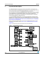
Figure 2 summarizes the main functional blocks of the evaluation board.
Figure 2. Evaluation board overview
STM32F0518
IrDA
Transceiver
1.8V Regulator
Audio
Amplifier
Microphone
Amplifer
MC Control
Connector
LEDs,
JTAG
Temperature
Sensor
Potentiometer
USART 1
DB9 Connector
ADC
DAC
GPIO
USART1
I2C1
Tamper Boutton
RS232
Transceiver
SPI1
MC
HDMI
Connector 1
STLINK
Debug
USB type B
Connector
HDMI
Connector 2
I2C1/I2C2
CEC
TFT LCD
MicroSD
Card
RF
EEPROM
TIM2
IRLED
Receiver
IRTIM
Transmitter
TIM16/TIM17
USART 1
DB9 Connector
RS485
Transceiver
JoyStick
Extension Connector
for GPIO
Extension Connector
for GPIO
3.3V Regulator
LDR
COMP
2.0V to 3.6 adjustable
Regulator

UM1520 Functional description
Doc ID 022862 Rev 1 7/66
1.1 Power control
The evaluation board can be powered from an external 5 V supply or from the USB
connector or ST-LINK/V2 connector. All other required voltages are provided by on-board
voltage regulators.
1.2 Clocking
Two clock sources are available on the STM320518-EVAL evaluation board:
●32 KHz crystal for embedded RTC
●8 MHz crystal for the STM32F051R8 main clock system
1.3 Reset control
The reset can be generated by hardware or software:
●Reset button: activates the RESET input when pressed
●JTAG reset
1.4 Debug JTAG interface
Software debug is done via the standard ARM® JTAG connection: 20-pin IDC (insulation
displacement connector) for connection to the standard ARM host interface.
1.5 Serial wire debugger interface
The Serial Wire Debug Port (SWD-DP) provides a 2-pin (clock + data) interface to the AHP-
AP port.
1.6 Embedded ST-LINK/V2
An embedded ST-LINK/V2 is integrated on the board as an embedded in-circuit debugger
and programmer for the STM32F051R8 MCU.
1.7 Display devices
1.7.1 LCD
A color LCD module is mounted on the STM320518-EVAL board. It is interfaced through the
embedded SPI peripheral.
1.7.2 LEDs
Four general-purpose LEDs are available. They are used as a display.

Functional description UM1520
8/66 Doc ID 022862 Rev 1
1.7.3 LDR (Light Dependent Resistor)
The VDDA is divided by the resistor bridge of LDR VT9ON1 & 8.2K resistor and connected
to PA1.
1.8 Interfaces
1.8.1 RS232 and RS485
The STM32F0518 evaluation board (STM320518-EVAL) provides one on-board RS-232
and RS485 serial ports. RS232 port (USART1) is accessed via CN7 connector.
1.9 IrDA
The STM320518-EVAL evaluation board supports IrDA communication. The interface is
mounted on USART1 (U1 interface).
1.10 Miscellaneous peripherals
1.10.1 Joystick
Four-direction joystick with a selection key.
1.10.2 Push-buttons
The following push-buttons are available:
●Key
●Tamper
●Wakeup (Joystick Sel): used to wake up the processor from low power mode
1.10.3 12-bit analog-to-digital converter (ADC)
Varistor: ADC channel (ADC1_IN11) connected to an on-board variable resistor. The variable
resistor provides a voltage in the range of 0 V to 3.3 V.
1.10.4 Audio
The STM320518-EVAL evaluation board implements a dedicated audio amplifier to be
interfaced with the STM32 DAC peripheral. For the audio output, a speaker and an audio
Jack are available on the board and connected to the DAC.
1.10.5 MicroSD card
The STM320518-EVAL evaluation board has a MicroSD card connector connected to the
SPI1 peripheral.

UM1520 Functional description
Doc ID 022862 Rev 1 9/66
1.10.6 Serial EEPROM
The STM320518-EVAL evaluation board includes a serial EEPROM connected to the SPI1
peripheral.
1.10.7 RF EEPROM
The RF EEPROM daughter board implemented on the module is the M24LR64-R. The
daughter board can be connected on CN2 to STM32F051R8 via the I2C bus. The I2C
address of the RF EEPROM is 0b1010E2E1E0. E0-E2 values are determined by the RF
EEPROM daughter board.
1.10.8 IR LED and IR receiver
The TSOP34836 IR receiver is connected to PB3 of STM32F051R8, and a current around
100mA on the IR LED is driven by PB9 through transistors T1 and T2 on the board.
1.10.9 HDMI CEC
Two HDMI connectors, CN3 and CN4, are available on the STM320518-EVAL board.
1.10.10 Temperature sensor
The STM320518-EVAL evaluation board includes an I2C temperature sensor connected to
the I2C1 peripheral.
1.10.11 Touch slider
Touch slider is supported on the STM320518-EVAL evaluation board and connected to 4
capacitive sensing channels.
1.10.12 STM320518-EVAL board jumper configuration
To be able to run the STM320518-EVAL demo correctly, configure the following
STM320518-EVAL board jumpers as follows:
●VDD Adjust: JP9 fitted pos VDD
●VDD Voltage: JP10 fitted pos 3.3V
●VDD Analog: JP11 fitted
●VDD VBat: JP12 fitted pos VDD
●VDD MCU: JP7 fitted
●Audio Output: JP13 fitted
●When running the LDR demo, jumper JP13 “Audio output” should not be fitted, to avoid
noise on the speaker
●JP5, JP6 and CN8 are not fitted.

Running the demonstration UM1520
10/66 Doc ID 022862 Rev 1
2 Running the demonstration
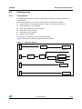
2.1 Menu
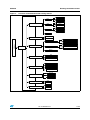
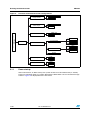
Due to code size constraints, the STM320518-EVAL demonstration firmware is provided
with 2 configurations. Figure 3 shows the menu system of the STM32F0518 demonstration
configuration1 and Figure 4 shows the menu system of the STM32F0518 demonstration
configuration2. The main menu is shown on the left-hand side. The UP, DOWN, RIGHT and
LEFT joystick directions allow the user to navigate between items in the main menu and the
submenus. To enter a submenu, press the SEL push-button.
The SEL push-button designates the action of vertically pressing the top of the joystick, as
opposed to moving it horizontally UP, DOWN, RIGHT or LEFT.
To exit a submenu, select the Return menu and press SEL.

UM1520 Running the demonstration
Doc ID 022862 Rev 1 11/66
Figure 3. Structure of the demonstration config1 menus
STM32 Stingray Welcome
message
Main menu
Calendar Date
Return
Low Power
About
Return
About
Adjust
Show
Return
Time
Adjust
Show
Return
Alarm
Adjust
Show
Return
Help Return
Help
RF EEPROM
Return
ESL
DataLogger (T)
WaveRecord
Return
Record
Player
Application
Return
StopWatch
Timer
LDR
Thermometer Return
Temperature
Return
STOP
STANDBY
Return
Exit: EXTI
Exit: RTC Alarm
Return
Exit: Wakeup Pin
Exit: RTC Alarm

Running the demonstration UM1520
12/66 Doc ID 022862 Rev 1
Figure 4. Structure of the demonstration config2 menus
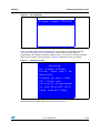
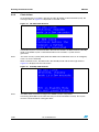
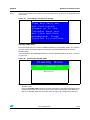
2.1.1 Demo startup
After a board reset, at demo startup, the system checks if an SD card memory is already
present in connector CN3. If no card is detected, the demo does not start and the message
shown in Figure 5 is displayed on the LCD screen.
STM32 Stingray Welcome
message
Main menu
Images Viewer
Images Viewer
Wave Player
Return
Wave Player
About
Return
About
Help Return
Help
Return
HDMI CEC Return
HDMI CEC
Infra Led
Return
IR Transmitter
IR Receiver
Return
SIRC
RC5
Return
SIRC
RC5

UM1520 Running the demonstration
Doc ID 022862 Rev 1 13/66
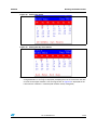
Figure 5. SD card check
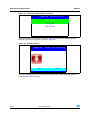
The demo continues only if an SD card is inserted.
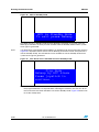
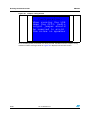
Then, the demo graphic icons and bitmap files are checked in the MicroSD card (see
Section 2.3.5: External memory organization). All the icons have to be correctly
programmed in the MicroSD card for the demo to start, so if an icon is missing, the demo
does not start and the message shown in Figure 6 is displayed on the LCD screen.
Figure 6. Warning message
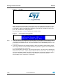
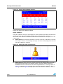
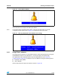
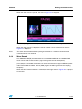
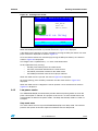
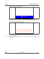
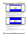
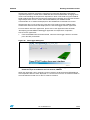
However, if the icons are correctly loaded into the SD Card memory, the welcome screen is
displayed and the ST logo appears on the LCD (see Figure 7).
Please insert SDcard
Please insert SDCard
Warning
No loaded Bitmap
files. Demo can't be
executed.
Please be sure that
all files are
correctly programmed
in the MicroSD card
then restart Demo

Running the demonstration UM1520
14/66 Doc ID 022862 Rev 1
Figure 7. ST logo
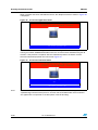
When the board is powered up for the first time, the user is prompted to set the time, year,
month and day. The user may choose to ignore it by pressing any key except for the SEL
push-button to abort the configuration sequence. To set the time and date, the user must
press SEL and follow the setting sequence.
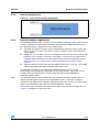
The message shown in Figure 8 appears on the LCD screen.
Figure 8. Time and date configuration
Note: 1 If the user chooses to configure the time and date, the Time Adjust and Date Adjust menus
are displayed. Otherwise, the main menu is displayed and the user can set the time
parameters in the Calendar menu. To set the time/date, use the UP/DOWN joystick and SEL
push-button.
2 If the time configuration has already been done, then the number of elapsed days (higher
than 1 day) from the last time the demo board was powered up appears on the LCD screen.
It is soon followed by the current date.
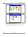
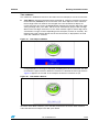
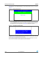
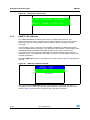
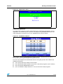
Once the time/date have been set, the main menu appears. The main menu is displayed in
the form of a set of icons. It shows all the submenus on the same screen. You can navigate
using the UP, DOWN, RIGHT and LEFT joystick directions to select the required submenu.
To enter a submenu, press the SEL joystick push-button, and the new submenu
corresponding to the selected icon is displayed.

UM1520 Running the demonstration
Doc ID 022862 Rev 1 15/66
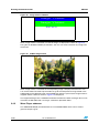
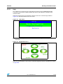
Figure 9. Main menu config1
Figure 10. Main menu config2
Note: The icons shown in Figure 9 and in Figure 10 are taken from
http://commons.wikimedia.org/wiki/Crystal_Clear.
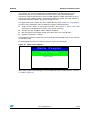
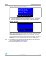
Once a submenu has been selected, the name of the application is listed at the top of the
display and all the corresponding submenus are listed below, as shown in Figure 11.
APP Main Menu Name
APP Main Menu Name

Running the demonstration UM1520
16/66 Doc ID 022862 Rev 1
Figure 11. Corresponding submenus
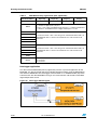
2.1.2 Navigation
The demonstration menu is based on circular navigation, submenu selection, item selection
and back navigation as described in Figure 12.
Figure 12. Navigating in the demonstration menus
The user navigates using the joystick push-buttons located on the evaluation board: RIGHT,
LEFT, SEL, UP and DOWN.
●The UP, DOWN, RIGHT and LEFT push-buttons are used to perform circular navigation
in the main menu and the current menu items.
●The SEL push-button selects the current item.
●The UP and DOWN push-buttons are used for vertical navigation in the submenus.
●To return to the upper menu, go to the Return line and press SEL.
Item 1 Item 2 Item 4
Item 5 Item 6 Item 8
Item 9 Item 10 Item 12
Left
Right
Up
Up
Left
Right
Left
Right
Left
Right
Left
Right
Left
Right
Up
Up
Down
Up
Down
Up
Down
Up
Down
Up
Down
Up
Down
Left
Right
Left
Down
DownDown
Left
Right Right
Item 3
Item 3.1
Item 3.2
Item 3.n
Return
….
Item 3.1.1
Item 3.1.2
Item 3.1.n
Return
….
Select
Select
Select
Select
Item 3
Item 7
Item 11
Left
Right
Left
Right
Left
Right

UM1520 Running the demonstration
Doc ID 022862 Rev 1 17/66
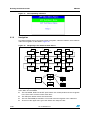
2.2 Clock sources
2.2.1 Clock control
The STM32F051R8 internal clocks are derived from the HSE (clocked by the external
8 MHz crystal).
In this demo application, the various system clocks are configured as follows:
●System clock is set to 48 MHz: the PLL is used as the system clock source.
●HCLK frequency is set to 48 MHz.
●Timer clock (TIMCLK) is set to 48 MHz.
●ADC clock is set to 14 MHz.
●CEC clock is set to 32 KHz.
●PCLK is set to 48 MHz.
Only the RTC is clocked by a 32 kHz external oscillator.
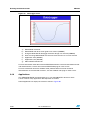
Figure 13 illustrates the clock tree organization for this demo.
Figure 13. Clock tree diagram
HSI RC
CEC
32 KHz
8 MHz
HSE
oscillator
PLL
Multiplicator
X6
AHB
Prescaler
/1 APB Prescaler
/1 TIM1/15/16/17
x1 mutliplier
PCLK to APB
peripherals
SYSCLK
8 MHz x6 =>
48 MHz
48 MHz
48 MHz
8 MHz
48 MHz
LSE
oscillator
RTC
32 KHz
32 KHz
HCLK 48MHz to AHB
Bus, coe, memory and
DMA
HSI 14
RC
ADC
14MHz
14 MHz
HSI Prescaler
/244

Running the demonstration UM1520
18/66 Doc ID 022862 Rev 1
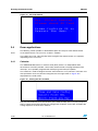
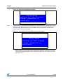
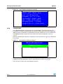
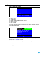
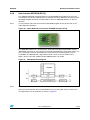
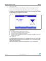
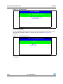
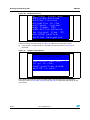
2.2.2 Clock failure
At any demo level, if no clock is present on OSC_IN (broken or disconnected crystal), the
message shown in Figure 14 is displayed on the LCD screen.
Figure 14. No HSE clock detected
If the 8 MHz crystal is not reconnected in the next few seconds, the MCU enters the Standby
mode. If the 8 MHz crystal is reconnected within a few seconds, a system reset is
generated.
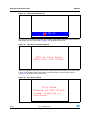
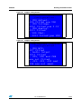
Note: The clock security system (CSS) feeds the MCU with the MSI OSC used as an emergency
clock if no clock is detected.
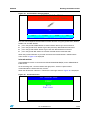
When a timeout occurs, the MCU enters the Standby mode and the message shown in
Figure 15 is displayed on the LCD screen.
Figure 15. Standby mode entered
Note: The demo does not restart as long as the 8 MHz crystal is not present.
Connecting the 8 MHz crystal after reset may not restart the demo correctly. The crystal
must be connected before starting the demo.

UM1520 Running the demonstration
Doc ID 022862 Rev 1 19/66
2.3 STM32F051R8(T6) resources
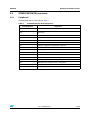
2.3.1 Peripherals
All used peripherals are described in Table 1.
Table 2. STM32F051R8(T6) demo peripherals
Used peripherals Application
I2C1 Temperature sensor, dual interface EEPROM and CEC
EXTI Menu navigation + joystick + push-button + low power mode + audio +
Applications
GPIO All applications + LEDs
NVIC All applications using interrupts
PWR Low power modes
RCC All applications + Demo kernel
RTC Calendar + Applications (StopWatch and Timer)
SysTick Generate 10 ms time base
TIM15 LED toggling
TIM3 and TIM4 Voice recording + Voice player
TIM2 Tim16 and TIM17 Infra Led Transmitter and Receiver + CEC Demo
ADC1 Voice recording + IDD measure
CEC CEC Demo
DAC LDR (define the comparator level) + wave player
SPI1 MicroSD + Color LCD
COMP LDR (Brightness level)

Running the demonstration UM1520
20/66 Doc ID 022862 Rev 1
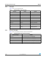
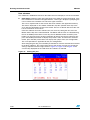
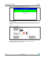
2.3.2 Interrupts
Table 2 shows all the enabled interrupts.
2.3.3 External interrupts
Table 3 shows all the external interrupts used by the demonstration.
Table 3. STM32F051R8(T6) demo interrupts
Interrupts Priority Used for
SysTick SubPriority: 0 System timing
NMI Priority: -2 CSS interrupt
EXTI0_1 Priority: 0 Wake-Up button
EXTI4_15 Priority: 1 Menu navigation
TIM6_DAC Priority: 0 Wave Player
I2C1 Error Priority: 0 SMBus Alert interrupt
TIM2_UP Priority: 0 Infra Led Receiver interrupt
TIM3_UP Priority: 2 Wave Record interrupt
TIM14_CC Priority: 1 Wave Record interrupt
TIM15_UP Priority: 1 LED toggling
TIM16_UP Priority: 0 Infra Led Transmitter interrupt
RTC Priority: 1 Calendar, date update, Tamper
and Alarm generation
CEC Priority: 0 CEC interrupt
Table 4. STM32F051R8(T6) demo external interrupts
External interrupts Used for
EXTI line 0 Joystick SEL (interrupt mode, falling edge)
EXTI line 6 Joystick UP (interrupt mode, falling edge)
EXTI line 7 Joystick DOWN (interrupt mode, falling edge)
EXTI line 8 User Button (interrupt mode, falling edge)
EXTI line 15 SD Card detect (interrupt mode, rising and falling edge)
EXTI line 17 RTC Alarm (interrupt mode, rising edge)
Page is loading ...
Page is loading ...
Page is loading ...
Page is loading ...
Page is loading ...
Page is loading ...
Page is loading ...
Page is loading ...
Page is loading ...
Page is loading ...
Page is loading ...
Page is loading ...
Page is loading ...
Page is loading ...
Page is loading ...
Page is loading ...
Page is loading ...
Page is loading ...
Page is loading ...
Page is loading ...
Page is loading ...
Page is loading ...
Page is loading ...
Page is loading ...
Page is loading ...
Page is loading ...
Page is loading ...
Page is loading ...
Page is loading ...
Page is loading ...
Page is loading ...
Page is loading ...
Page is loading ...
Page is loading ...
Page is loading ...
Page is loading ...
Page is loading ...
Page is loading ...
Page is loading ...
Page is loading ...
Page is loading ...
Page is loading ...
Page is loading ...
Page is loading ...
Page is loading ...
Page is loading ...
-
 1
1
-
 2
2
-
 3
3
-
 4
4
-
 5
5
-
 6
6
-
 7
7
-
 8
8
-
 9
9
-
 10
10
-
 11
11
-
 12
12
-
 13
13
-
 14
14
-
 15
15
-
 16
16
-
 17
17
-
 18
18
-
 19
19
-
 20
20
-
 21
21
-
 22
22
-
 23
23
-
 24
24
-
 25
25
-
 26
26
-
 27
27
-
 28
28
-
 29
29
-
 30
30
-
 31
31
-
 32
32
-
 33
33
-
 34
34
-
 35
35
-
 36
36
-
 37
37
-
 38
38
-
 39
39
-
 40
40
-
 41
41
-
 42
42
-
 43
43
-
 44
44
-
 45
45
-
 46
46
-
 47
47
-
 48
48
-
 49
49
-
 50
50
-
 51
51
-
 52
52
-
 53
53
-
 54
54
-
 55
55
-
 56
56
-
 57
57
-
 58
58
-
 59
59
-
 60
60
-
 61
61
-
 62
62
-
 63
63
-
 64
64
-
 65
65
-
 66
66


STMicroelectronics STSW-STM32122 User manual
- Category
- Sport watches
- Type
- User manual
- This manual is also suitable for
Ask a question and I''ll find the answer in the document
Finding information in a document is now easier with AI
Related papers
-
STMicroelectronics STM32303E-EVAL User manual
-
STMicroelectronics DEMOKIT-M24LR-A User manual
-
STMicroelectronics STM8L1528-EVAL User manual
-
STMicroelectronics SPC58XXADPT144S User manual
-
ST STM32WB30CE Reference guide
-
-
-
-
Arduino MicroMod STM32WB5MMG Processor Reference guide
-
Other documents
-
ST 32C0116-DK Discovery kit User manual
-
-
ST com STM32HSM-V2 Operating instructions
-
-
ST com STM32C0 Operating instructions
-
-
-
Transmitter 295SEPC1V Owner's manual
-
-
Grandstream Networks UCM6 series User manual