Page is loading ...

180/250 mm RECORDER REMOTE CJ OPTION
HA250661
Issue 3 Feb 99
Page 1
Remote CJ option
180/250mm recorders
1 INTRODUCTION
This document is intended to explain the installation and use of 'Remote' Cold Junction Compensation (CJC) for
those users who require a greater accuracy and rejection ratio than are supplied by the recorder's internal CJC.
The option is available either as a complete unit fitted by the manufacturer and ready to use, or as a retrofit kit.
For this reason, this document is written as a number of 'stand-alone' sections, which the user may make use of as
necessary
As explained in the installation and operation manual supplied with the recorder, each input channel can be con-
figured to have internal, external or remote CJC (section 4.4.2). In the case of 'remote' one or more input channels
are set up (in 'Instrument configuration - section 4.2.1) to measure the temperature of the cold junction (CJ). With
this option, channel 1 is used to measure the CJ temperature for channels 2 to 24.
Channel 1 uses a platinum resistance thermometer to measure the CJ temperature. For this reason, channel 1 must
be related to an 8-channel universal input board because the 16-channel board does not support resistance inputs.

Page 2
HA250661
Issue 3 Feb 99
180/250 mm RECORDER REMOTE CJ OPTION
2 SPECIFICATION
The following specification is additional to or replaces parts of the specification given in Annex A of the Installa-
tion and Operation Manual.
Warning!
This unit is for use with isolation voltages of <30V RMS or < 60V dc only
Remote CJ option specification
CJC rejection ratio 100:1
CJC accuracy (after calibration) ± 0.2 ˚C
CJC stability ±0.06 ˚C at 1 ˚C/hr rate-of-change in ambient temperature
Total T/C repeatability under normal operating conditions
± 0.2 ˚C over an ambient range of 20 ˚C to 30 ˚C.
Resistance thermometer type Pt
100
Start-up time
Recorder at ambient: to within 0.1˚C of final value within 2 mins.
Recorder at 20˚C above/below ambient: to within 0.1˚C of final value within 30 mins.
2.1 COLD JUNCTION REJECTION RATIO, ACCURACY AND STABILITY
The performance of a remote CJ can be described as the response to a change in steady-state temperature, and to
the speed at which the temperature is changing. the following example attempts to explain the CJ figures given in
the specification above.
An instrument is 'adjusted' * (section four of the installation and operation manual) at an ambient temperature of
25˚C. This adjust procedure removes the effects of individual thermocouple errors and of the CJC accuracy
(±
0.2˚C) at the adjust temperatures.
The ambient temperature then rises to 30˚C over a period of two hours - a change of 5˚C at a rate of 2.5˚C/hour,
The new reading error is the total change multiplied by the rejection ratio (5 x 1/100) = 0.05˚C when the tempera-
ture stabilises at 30˚C.
DURING the change, there is an additional error calculated by multiplying the rate of change by the CJC Stabil-
ity value i.e. 2.5 x 0.06 = 0.15˚C.
In a real environment, the temperature is always changing, and in an office-type area, it is reasonable to assume
a 1˚C/hour change in ambient, resulting in an error of 0.06˚C which is present at all temperatures, even during the
adjust procedure.
The unit has been designed to 'filter' short term rapid changes in temperature, but to minimise ambient-related
errors consideration should be given to the location of the recorder. For example, it is not advisable to place the
unit near the door to a cold room.
* Channel 1 must be adjusted before other channels. Channel 1 is adjusted by disconnecting one of the RTD leads
from the instrument terminal block and connecting a standard resistance box across the terminals. Values of 0˚C
(100Ω) and 100˚C (138.5Ω) should be used.
Note: If the software version of your recorder is 4.2, it is necessary to add a one minute delay to the
adjust procedure. I.E. when the instrument asks for a high value to be set, wait for one minute before
doing so. Failure to wait will result in incorrect adjustment of channels 7 and 8 of each card. Other
software versions have a built-in delay.

180/250 mm RECORDER REMOTE CJ OPTION
HA250661
Issue 3 Feb 99
Page 3
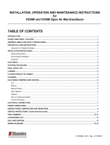
Figure 3 Overall dimensions
3 DIMENSIONS
The overall length of the recorder is increased as shown in figure 3. When calculating available depths, remem-
ber to leave sufficient room for the thermocouple cables.
4 WIRING
4.1 Thermocouple connectors
Figure 4.1 shows channel wiring information for a full set of T/C connectors. Where only 8 or 16 channels are
used, blanking plates cover the remaining space.
Figure 4.1 Channel layout for T/C connectors.
CH 24 CH 22 CH 20 CH 18 CH 16 CH 14 CH 12 CH 10 CH 8 CH 6 CH 4 CH 2
CH 23 CH 21 CH 19 CH 17 CH 15 CH 13 CH 11 CH 9 CH 7 CH 5 CH 3
++++++++++++
+++++++++++
Channel numbers
Channel numbers
232119171513119753
24222018161412108642
View on top
View on right
hand side
415 mm (16.35 in)
561 mm (22.1 in)
View on right
hand side
View on top
180mm recorders250mm recorders

Page 4
HA250661
Issue 3 Feb 99
180/250 mm RECORDER REMOTE CJ OPTION
4.2 TERMINAL BLOCK ACCESS
To gain access to the terminal blocks, the 'U'-shaped back/side cover must be removed by undoing the 4 securing
screws (two on each side), as indicated in figure 4.2a. Once the cover is removed, access can be gained to the
terminal blocks, the channel layout of which is shown in figure 4.2b. Channel 1 is not available to the user.
Figure 4.2a Cover removal
Figure 4.2b Channel wiring
5 CONNECTOR REMOVAL
After first releasing the RFI grounding tag, the connectors are
removed from the recorder rear panel, using two screwdrivers
(or similar) to depress the catches at each end and to prise the
connector out.
Figure 5b Connector removal (250mm recorders)
Figure 5a Connector removal (180mm recorders)
–
CH 12
+–
CH 10
+–
CH 8
+–
CH 5
+–
CH 4
+–
CH 2
+
CH 23 CH 21 CH 19 CH 17 CH 15 CH 13
–+–+– +–+–+–+
–
CH 24
+–
CH 22
+–
CH 20
+–
CH 18
+–
CH 16
+–
CH 14
+
CH 11 CH 7 CH 5 CH 3
+–+–+–+–+–
CH 9
To RTD
24 22 20 18 16 14 12 10 8 6 4 2
23 21 19 17 15 13 11 9 7 5 3

180/250 mm RECORDER REMOTE CJ OPTION
HA250661
Issue 3 Feb 99
Page 5
6 FITTING THE REAR CONNECTORS
The connectors are fitted (usually) at slots 1 and 2 of the recorder. Figure 6 shows a typical arrangement for a 250
mm recorder. 180mm recorders are similar, but the slots are horizontal with connector 1 at top right (connectors 3
and 5 below) and connector 2 at top left (connectors 4 and 6 below).
Figure 6 Connector fitting (250mm recorders)
7 WIRING SKETCHES
The retrofit unit comes with connectors for three 8-input channel boards, and figure 7.1 below shows wiring from
the T/C sockets to three 8-channel Universal input boards, using six connectors and two cable harnesses.
For fewer 8-channel input boards, only the connectors/harness(es) which are relevant should be used.
To use one 8-channel input board and one 16-channel input board, the user has to re-wire the connectors as shown
in figure 7.2 on pages 8 and 9.
With such a configuration, channel one to eight must be associated with the 8-channel board, and channels nine to
24 with the 16-channel board.

Page 6
HA250661
Issue 3 Feb 99
180/250 mm RECORDER REMOTE CJ OPTION
Figure 7.1 Sheet 1. Wiring details for channels 1 to 8 using three 8-channel input boards
7 WIRING SKETCHES (Cont.)
18 (C)
17 (V)
16 (I)
15
14 (C)
13 (V)
12 (I)
11
10
9
8
7 (C)
6 (V)
5 (I)
4
3 (C)
2 (V)
1 (I)
Channel 3
14243
Channel 2
T/C Connector
–
+
–
+
–
+
–
+
–
+
–
+
–
+
–
+
Red
Red/Blue
Channel 4
14243
Channel 2
14243
Channel 1
Channel 3
T/C Connector
–
+
Orange
Orange/Blue
Channel 4
T/C Connector
–
+
Yellow
Yellow/Blue
14243
18 (C)
17 (V)
16 (I)
15
14 (C)
13 (V)
12 (I)
11
10
9
8
7 (C)
6 (V)
5 (I)
4
3 (C)
2 (V)
1 (I)
Channel 7
14243
Channel 6
T/C Connector
–
+
Connector 2
(Cable 1)
Blue
Blue/Black
Channel 8
14243
Channel 6
14243
Channel 5
Channel 7
T/C Connector
–
+
Violet
Turquoise
Channel 8
T/C Connector
–
+
Grey
Yellow/Red
Channel 5
T/C Connector
–
+
Green
Green/Red
8-channel
Universal input
board
Terminal
block I/O Board 1
Channel 8
Connector 1
(Cable 1)
Channel 7
Channel 6
Channel 5
Channel 4
Channel 3
Channel 2
RTD
Pt
100
Black
Brown
14243

180/250 mm RECORDER REMOTE CJ OPTION
HA250661
Issue 3 Feb 99
Page 7
7 WIRING SKETCHES (Cont.)
Figure 7.1 Sheet 2. Wiring details for channels 9 to 16 using three 8-channel input boards
18 (C)
17 (V)
16 (I)
15
14 (C)
13 (V)
12 (I)
11
10
9
8
7 (C)
6 (V)
5 (I)
4
3 (C)
2 (V)
1 (I)
Channel 11
14243
Channel 10
T/C Connector
–
+
Pink
Red/Black
Channel 12
14243
Channel 10
14243
Channel 9
Channel 11
T/C Connector
–
+
Red/Brown
White/Blue
Channel 12
T/C Connector
–
+
Yellow/Green
White Green
14243
18 (C)
17 (V)
16 (I)
15
14 (C)
13 (V)
12 (I)
11
10
9
8
7 (C)
6 (V)
5 (I)
4
3 (C)
2 (V)
1 (I)
Channel 15
14243
Channel 14
T/C Connector
–
+
Red
Red/Blue
Channel 16
14243
Channel 14
14243
Channel 13
Channel 15
T/C Connector
–
+
Orange
Orange/Blue
Channel 16
T/C Connector
–
+
Yellow
Yellow/Blue
Channel 13
T/C Connector
–
+
Brown
Black
Connector 4
(Cable 2)
Connector 3
(Cable 1)
8-channel
Universal input
board
Terminal
block
I/O Board 2
Channel 16
Channel 15
Channel 14
Channel 13
Channel 12
Channel 11
Channel 10
Channel 9
T/C Connector
–
+
White
White/Red
Channel 9
–
+
–
+
–
+
–
+
–
+
–
+
–
+
–
+
14243

Page 8
HA250661
Issue 3 Feb 99
180/250 mm RECORDER REMOTE CJ OPTION
Figure 7.1 Sheet 3. Wiring details for channels 17 to 24 using three 8-channel input boards
7 WIRING SKETCHES (Cont.)
Channel 17
T/C Connector
–
+
Green
Green/Red
18 (C)
17 (V)
16 (I)
15
14 (C)
13 (V)
12 (I)
11
10
9
8
7 (C)
6 (V)
5 (I)
4
3 (C)
2 (V)
1 (I)
Channel 19
14243
Channel 18
T/C Connector
–
+
Blue
Blue/Black
Channel 20
14243
Channel 18
14243
Channel 17
Channel 19
T/C Connector
–
+
Violet
Turquoise
Channel 20
T/C Connector
–
+
Grey
Yellow/Red
14243
18 (C)
17 (V)
16 (I)
15
14 (C)
13 (V)
12 (I)
11
10
9
8
7 (C)
6 (V)
5 (I)
4
3 (C)
2 (V)
1 (I)
Channel 23
14243
Channel 22
T/C Connector
–
+
Connector 6
(Cable 2)
Pink
Red/Black
Channel 24
14243
Channel 22
14243
Channel 21
Channel 23
T/C Connector
–
+
Red/Brown
White/Blue
Channel 24
T/C Connector
–
+
Yellow/Green
White/Green
Channel 21
T/C Connector
–
+
White
White/Red
Terminal
block I/O Board 3
Channel 24
Connector 5
(Cable 2)
Channel 23
Channel 22
Channel 21
Channel 20
Channel 19
Channel 18
Channel 17
–
+
–
+
–
+
–
+
–
+
–
+
–
+
–
+
14243
8-channel
Universal input
board

180/250 mm RECORDER REMOTE CJ OPTION
HA250661
Issue 3 Feb 99
Page 9
18 (C)
17 (V)
16 (I)
15
14 (C)
13 (V)
12 (I)
11
10
9
8
7 (C)
6 (V)
5 (I)
4
3 (C)
2 (V)
1 (I)
Channel 3
14243
Channel 2
T/C Connector
–
+
–
+
–
+
–
+
–
+
–
+
–
+
–
+
Red
Red/Blue
Channel 4
14243
Channel 2
14243
Channel 1
Channel 3
T/C Connector
–
+
Orange
Orange/Blue
Channel 4
T/C Connector
–
+
Yellow
Yellow/Blue
14243
18 (C)
17 (V)
16 (I)
15
14 (C)
13 (V)
12 (I)
11
10
9
8
7 (C)
6 (V)
5 (I)
4
3 (C)
2 (V)
1 (I)
Channel 7
14243
Channel 6
T/C Connector
–
+
Connector 2
(Cable 1)
Blue
Blue/Black
Channel 8
14243
Channel 6
14243
Channel 5
Channel 7
T/C Connector
–
+
Violet
Turquoise
Channel 8
T/C Connector
–
+
Grey
Yellow/Red
Channel 5
T/C Connector
–
+
Green
Green/Red
8-channel
Universal input
board
Terminal
block I/O Board 1
Channel 8
Connector 1
(Cable 1)
Channel 7
Channel 6
Channel 5
Channel 4
Channel 3
Channel 2
RTD
Pt
100
Black
Brown
14243
7 WIRING SKETCHES (Cont.)
Figure 7.2 Sheet 1. Wiring details for channels 1 to 8 using one 8-channel and one 16-channel input board

Page 10
HA250661
Issue 3 Feb 99
180/250 mm RECORDER REMOTE CJ OPTION
7 WIRING SKETCHES (Cont.)
18 (V-)
17 (V+)
16 (V-)
15 (V+)
14 (V-)
13 (V+)
12 (V-)
11 (V+)
10
9
8 (V-)
7 (V+)
6 (V-)
5 (V+)
4 (V-)
3 (V+
2 (V-)
1 (V+)
Ch 18
–
+
–
+
–
+
Ch 17
–
+
Blue
Blue/Black
Green
Green/Red
Ch 20
–
+
–
+
Channel 19
T/C Connector
–
+
Ch 19
–
+
Channel 17
T/C Connector
Violet
Turquoise
Grey
Yellow/Red
Channel 17
123
Connector 4
(Cable 2)
Channel 20
T/C Connector
Channel 18
T/C Connector
Ch 22
–
+
–
+
–
+
Ch 21
–
+
Pink
Red/Black
White
White/Red
Ch 24
–
+
–
+
Channel 23
T/C Connector
–
+
Ch 23
–
+
Channel 21
T/C Connector
Red/Brown
White/Blue
Yellow/Green
White/Green
Channel 24
T/C Connector
Channel 22
T/C Connector
Channel 18
123
Channel 19
123
Channel 20
123
Channel 21
123
Channel 22
123
Channel 23
123
Channel 24
123
Connector 4
(Cable 2)
18 (V-)
17 (V+)
16 (V-)
15 (V+)
14 (V-)
13 (V+)
12 (V-)
11 (V+)
10
9
8 (V-)
7 (V+)
6 (V-)
5 (V+)
4 (V-)
3 (V+
2 (V-)
1 (V+)
Ch 10
–
+
–
+
–
+
Ch 9
–
+
Pink
Red/Black
White
White/Red
Ch 12
–
+
–
+
Channel 11
T/C Connector
–
+
Ch 11
–
+
Channel 9
T/C Connector
Red/Brown
White/Blue
Yellow/Green
White Green
Channel 9
123
Connector 3
(Cable 1)
Channel 12
T/C Connector
Channel 10
T/C Connector
Ch 14
–
+
–
+
–
+
Ch 13
–
+
Red
Red/Blue
Brown
Black
Ch 16
–
+
–
+
Channel 15
T/C Connector
–
+
Ch 15
–
+
Channel 13
T/C Connector
Orange
Orange/Blue
Yellow
Yellow/Blue
Channel 16
T/C Connector
Channel 14
T/C Connector
Channel 10
123
Channel 11
123
Channel 12
123
Channel 13
123
Channel 14
123
Channel 15
123
Channel 16
123
Connector 3
(Cable 2)
16-channel dc
input board
I/O Board 2
Terminal
block
Figure 7.2 Sheet 2. Wiring details for channels 9 to 24 using one 8-channel and one 16-channel input board

180/250 mm RECORDER REMOTE CJ OPTION
HA250661
Issue 3 Feb 99
Page 11
This page is deliberately left blank

Germany
Eurotherm Meßdatentechnik GmbH
Ottostraße 1,
D-65549 Limburg a.d.Lahn
Tel: 49 64 31 9173 0
Fax: 49 64 31 9173 33
Great Britain
Eurotherm Recorders Limited,
Dominion Way,
Worthing,
West Sussex BN14 8QL
Telephone: 01 903 205222
Telex: 877296 CHESEL G
Fax: 01 903 203767
Email: [email protected]
Web: http://www.eurotherm.co.uk
Hong Kong
Eurotherm Limited,
Unit D, 18/F Gee Chang Hong Centre,
65, Wong Chuk Hang Road,
Aberdeen.
Telephone: 852 2873 3826
Telex: 69257EIFEL HX
Fax: 852 2870 0148
India
Eurotherm Del India Limited,
152, Developed Plots Estate,
Chennai 600 096,
Telephone: 91 44 4961129
Fax: 91 44 4961831
Italy
Eurotherm SpA,
Via XXIV Maggio,
I-22070 Guanzate,
Como.
Telephone: 39 031 975111
Fax: 39 031 977512
Japan
Densei Lambda K.K.,
Strategic Products Dept.
5F Nissay Aroma Square,
37-1, Kamata, 5-Chome,
Ohta-ku,
Tokyo 144-8721
Telephone: 81 3 5714 0620
Fax: 81 3 5714 0621
Web: http://www.densei-lambda.com
Inter-Company sales and service locations
Korea
Eurotherm Korea Limited,
J- Building
402-3
Poongnab-Dong,
Songpa-Ku
Seoul, 138-040
Telephone: 82 2 2478 8507
Fax: 82 2 488 8508
Netherlands
Eurotherm BV,
Genielaan 4,
2404CH Alphen aan den Rijn,
The Netherlands
Telephone: 31 172 411 752
Fax: 31 172 417 260
Norway
Eurotherm A/S,
Vollsveien 13D
1366 Lysaker,
Postboks 227
NO-1326 Lysaker
Norway,
Telephone: 47 67 592170
Fax: 47 67 118301
Spain
Eurotherm España SA,
Pol. Ind. De Alcobendas,
Calle de la Granja 74,
28108 Alcobendas,
Madrid.
Telephone: 34 91 661 60 01
Fax: 34 91 661 90 93
Sweden
Eurotherm AB,
Lundavägen 143,
S-21224 Malmö.
Telephone: 46 40 38 45 00
Fax: 46 40 38 45 45
Switzerland
Eurotherm Produkte (Schweiz) AG,
Schwerzistraße, 20,
CH-8807 Freienbach.
Telephone: 41 55 415 44 00
Fax: 41 55 415 44 15
United States of America
Eurotherm Recorders Inc.
One Pheasant Run,
Newtown Industrial Commons,
Newtown PA 18940.
Telephone: 1 215 968 0660
(Toll-free USA/Canada: 1 888 7097 2475)
Fax: 1 215 968 0662
Web: http://www.chessell.com
e-mail:[email protected]
Specification subject to change without notice. ©Eurotherm Limited.
Australia
Eurotherm Pty. Limited.
Unit 10.
40 Brookhollow Avenue,
Baulkham Hills,
NSW 2153
Telephone: 61 2 9634 8444
Fax: 61 2 9634 8555
Email: [email protected]
Austria
Eurotherm Meß-und Regeltechnik GmbH
Geiereckstraße 18/1,
A1110 Wien,
Telephone: 43 1 798 76 01
Fax: 43 1 798 76 05
Belgium
Eurotherm BV,
Herentalsebaan 71-75,
B 2100 Deurne
Antwerpen
Telephone: 32 3 320 8550
Fax: 32 3 321 7363
Denmark
Eurotherm Danmark A/S
Finsensvej 86,
DK 2000 Fredriksberg,
Telephone: 45 38 871622
Fax: 45 38 872124
Finland
Eurotherm Finland,
Auragaten 12A,
FIN-20100 Åbo
Telephone: 358 22 50 60 30/1
Fax: 358 22 50 32 01
France
Eurotherm Chessell
Une division d'Eurotherm Automation SA,
Parc d'affaires,
6, Chemin des Joncs,
BP55
F - 69572 Dardilly, CEDEX
Telephone: 33 4 78 66 45 00
Fax: 33 4 78 35 24 90
EUROTHERM LIMITED
Faraday Close, Durrington, Worthing, West Sussex, BN13 3PL
Telephone: 01903 205222. Facsimile: 01903 203767
e-mail: [email protected]
Website: http://www.eurotherm.co.uk
ε
EUROTHERM
HA250661/3A (D7519)
/