Page is loading ...

4/17 Rev. D 57-02089
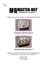
Installation & Operations Manual
Master-Bilt Products
908 Highway 15 North
New Albany, MS 38652
Phone: (800) 684-8988

2
TABLE OF CONTENTS
INTRODUCTION………………………………….…………………………………………………………………… 3
STORE CONDITIONS…………………………….……………….…..……………………………………………... 3
WARNING LABELS AND SAFETY INSTRUCTIONS………..…..………………………………………………. 4
PRE-INSTALLATION INSTRUCTIONS………………………..…..………………………………….………… 5
Inspection for Shipping Damage…………………………………………………………….…………….. 5
INSTALLATION INSTRUCTIONS………………………………………………………………………………….. 5
General Instructions…………………………………………………………………………………………. 5
Mechanical……………………………………………………………………………………………………. 5
Location……………………………………………………………………………………………………….. 5
CABINET CLEANING PROCEDURES…………………………………………………………………………….. 6
SERVICE INSTRUCTIONS………………………………………………………………………………………….. 6
Electrical………………………………………………………………………………………………………. 7
Lighted sign canopy installation…………………………………………………………………………….. 8
Special Service Situations…..……………..………………………………………………………………. 9
Operating Conditions and Pressures……..………………………………………………………………. 9
Temperature Sensor, Defrost Heater, and Fan Motor Replacement………………………………….. 9
Electronic Refrigeration Control..……………………………………………………………………………….. 10
Operations…………………………………………………………………………………………………. 10
Defrost & Manual Defrost.…………...……………………………………………………………………… 10
Temperature Setpoint……………………..………………………………………………………………. 11
List of Parameters……………………………………..………..…………………………………………… 11
Alarm Signals………………………………………………………………………………………………… 11
Electrical Connections………………………………………………………………………………………. 11
Probe Connections………………………………………………………………………………………… 11
SENSOR PROBE TEMP. AND RESISTANCE…………………………………………………...….…………….12
FAN OPERATION & VIBRATION, VOLTAGE CHECK………………………………………………………… 12
FINAL CHECK LIST..………………………………………………………………………………….……………... 12
MASTER-BILT
®
PARTS LIST…….………………………………………………………………………………… 13
SALE AND DISPOSAL………………………………………………………………………………………………. 13
WIRING DIAGRAM …………..………………………………….……………………….………………………..14-15

3
INTRODUCTION
Thank you for purchasing a Master-Bilt
®
cabinet. This manual contains important instructions for installing, using, and
servicing a Master-Bilt
®
FIP case. A parts list is included with this manual. Read all these documents carefully before
installing or servicing your equipment.
STORE CONDITIONS
The Master-Bilt
®
FIP cases are designed to operate in the controlled environment of an air-conditioned store. The
store temperature should be at or below 75°F and a relative humidity of 55% or less. At higher temperature or humidity
conditions, the performance of these cases may be affected and the capacity diminished.
The Master-Bilt
®
FIPshould not be positioned where it is directly exposed to rays of sun or near a direct source of
radiant heat. This will adversely affect the case and will result in poor performance.
NOTICE
Read this manual before installing your cabinet. Keep the manual and refer to it before doing any service on
the equipment. Failure to do so could result in personal injury or damage to the cabinet.
DANGER
Improper or faulty hook-up of electrical components on the refrigeration units can result in severe injury or
death.
All electrical wiring hook-ups must be done in accordance with all applicable local, regional or national
standards.
NOTICE
Installation and service of the refrigeration and electrical components of the cabinet must be performed by a
refrigeration mechanic and/or a licensed electrician.
The portions of this manual covering refrigeration and electrical components contain technical instructions intended
only for persons qualified to perform refrigeration and electrical work.
This manual cannot cover every installation, use or service situation. If you need additional information, call or write us:
Customer Service Department
Master-Bilt Products
Highway 15 North
New Albany, MS 38652
Phone (800) 684-8988
Fax (800) 684-8988

4
CAUTION!
GROUND REQUIRED
FOR SAFE OPERATION
WARNING LABELS AND SAFETY INSTRUCTIONS
This symbol is the safety-alert symbol. When you see this symbol on your cabinet or in this
manual, be alert to the potential for personal injury or damage to your equipment.
Be sure you understand all safety messages and always follow recommended precautions and safe operating
practices.
NOTICE TO EMPLOYERS
You must make sure that everyone who installs, uses or services your cabinet is thoroughly familiar with all
safety information and procedures.
Important safety information is presented in this section and throughout the manual. The following signal words are
used in the warnings and safety messages:
DANGER: Severe injury or death will occur if you ignore the message.
WARNING: Severe injury or death can occur if you ignore the message.
CAUTION: Minor injury or damage to your cabinet can occur if you ignore the message.
NOTICE: This is important installation, operation or service information. If you ignore the
message, you may damage your cabinet.
The warning and safety labels shown throughout this manual are placed on your Master-Bilt
®
Products cabinet
at the factory. Follow all warning label instructions. If any warning or safety labels become lost or damaged,
call your customer service department at (800) 684-8988 for replacements.
This label is located on top of the electrical control This label is attached to the cabinet power cord
label and on the wiring channel.
on models with a power cord.

5
PRE-INSTALLATION INSTRUCTIONS
INSPECTION FOR SHIPPING DAMAGE
You are responsible for filing all freight claims with the delivering truck line. Inspect all cartons and crates for damage
as soon as they arrive. If damage is noted to shipping crates or cartons or if a shortage is found, note this on the bill of
lading (all copies) prior to signing.
If damage is discovered when the cabinet is uncrated, immediately call the delivering truck line and follow up the call
with a written report indicating concealed damage to your shipment. Ask for an immediate inspection of your concealed
damage item. Crating material must be retained to show the inspector from the truck line.
INSTALLATION INSTRUCTIONS
GENERAL INSTRUCTIONS
1. Be sure the equipment is properly installed by competent service people.
2. Keep the equipment clean and sanitary so it will meet your local sanitation codes. Clean the cabinet with a mild
detergent and water, then rinse.
3. Rotate your stock so that older stock does not accumulate. This is especially important for ice
cream. A "First-In, First-Out" rotation practice will keep the products in good salable condition.
4. Do not place product in the case when it is soft or partially thawed. Also, product should not be put in the case for at
least 6 hours after it is started.
5. Stock cases as quickly as possible, exposing only small quantities to store temperatures for short periods of time.
6. When replacing burned out fluorescent tubes, be sure that the electrical power to the lighting circuit is turned off.
MECHANICAL
Remove front grille and check refrigeration lines to see that they are free (not touching each other or compressor).
Spin condenser fan blade to see that it is free.
LOCATION
Remove cabinet from crate base and slide into location. Cabinet must be level from side to side and front to back for
correct draining of coil pan and for self-closing doors to operate correctly.
Check that all service valves (2) are open. Cut compressor hold-
down strap and remove the compressor. The springs are secured
for shipping by either tightening bolts or shipping strap. Remove the
strap or loosen the hold-down bolts so that the compressor floats
freely.
To comply with Sanitation requirements the cabinet must be sealed
to the floor with a N.S.F. listed silicone sealant, mounted on casters,
or with 6” minimum legs. 0” air space is required for the front and
each side. The top and back of the cabinet must be left open for
compliance.
Remove shipping supports from bottom edge and top edge of doors.

6
CABINET CLEANING PROCEDURES
WARNING!
To avoid electrical shock, disconnect main power supplies to the cabinet
before beginning this procedure. May have more than one disconnect switch.
The exterior of the cabinet should simply be wiped clean with a Warm damp cloth daily. This will be sufficient to keep
the merchandiser looking its finest. Do not use a brush, scouring pad, or any abrasive material on the painted
surfaces!
To clean the interior of the cabinet, the condensing unit and power to the cabinet lights should be shut off. Disconnect
all power before cleaning! All product in the cabinet should be removed and stored in an appropriate facility. All
shelving, trays, Pans, etc. should be removed and cleaned separately.
The interior (as well as the exterior) of the cabinet may be cleaned with a germicidal detergent at the manufacturer’s
recommended concentration. Do not use any ammonia-based products as this may damage components in the
cabinet. Again, do not use a brush, scouring pad, or any abrasive material on the painted surfaces. Use a soft brush
or cleaner pad for built-up dirt, stains, or spills. Care should be taken not to unnecessarily soak fan motors, electrical
connections, controls, or any wire raceway. Wipe all surfaces with a damp cloth. A sanitizer should then be thoroughly
sprayed onto the surfaces and again wiped with a damp cloth.
Remove only the necessary mechanical parts to access the condenser coil and compressor housing. Care should
again be taken not to unnessarily soak fan motors, electrical connections, time clock, or any wire raceway. Check the
condenser coil to insure that it is not clogged with dirt, dust, or lint. A dirty or clogged condenser coil will result in
diminished performance of the cabinet. Use compressed air to blow the dirt through the condenser coil. Do not let dust
or dirt accumulate on the fan blades. If dust or dirt is noticeable, simply wipe the fan blades with a damp cloth as with
other surfaces. After cleaning, replace any equipment that was previously removed and start the condensing unit and
return power to the lights and fans.
CLEANING:
As a regular maintenance routine, the condenser coil should be cleaned approx every 6 to 12 months,
depending on store conditions.
Keep the equipment clean and sanitary so it will meet your local sanitation codes. Wipe up all spills, clean with water
and a mild detergent, then rinse with clean water. Wipe the exterior and gasket area as needed.
SERVICE INSTRUCTIONS
ELECTRICAL
WARNING
Before servicing electrical components in the case or the doors or door frames make sure all power to case is
off. Always use a qualified technician.
It is recommended that a separate circuit be run for each cabinet to prevent another appliance blowing the fuse or
HAC&R C/B, causing loss of product. This circuit should be sized according to the amp rating on the cabinet data
label.
NOTICE
For mode
ls with electronic ballast and florescent light only

7
For replacement ballast, use only ballast that complies with UL Type CC rating if unit is equipped with
electronic ballast.
WARNING Before making any change, the technician should disconnect power to the cabinet.
For models with LED lamp without ballast only
The light fixture has been redesigned and only suitable for specified self-ballasted LED
(Part # 23-01929 & 23-01931) mentioned in service manual and wiring diagram. In no case,
any florescent tube light can be used in this fixture.
• These lamp should be installed by licensed electricianas per local code.
• These lamps are to be used in indoor dry and damp location only.
• Not suitable for wet locations
• Risk of fire or electric shock
• These product is intended to be used with only the specific LED lamp. It is dangerous to use any other
lamp which is not specified here.

8
LIGHTED SIGN IN CANOPY INSTALLATION
1. Disconnect the power to the cabinet
2. Slide the finger below the canopy lens as shown and push the lens up till it disengages from the lip of
the canopy.
3. Then slide down to take it out for service
4. While installing the lens please follow the instruction as shown in the pictures.
5. Make sure the top of the lens is securely positioned in the slot between the top retainer and top deck.
6. Once it is inbetween the top slot,push the lens up to make sure it is securely placed in the groove
created by the hem structure of the lip of the the front deck canopy area.

9
SPECIAL SERVICE SITUATION:
A. There are rare occasions when the refrigerant charge must be evacuated from a cabinet in order to perform
service work. In those situation, Master-Bilt recommends that a refrigerant reclaimer be used according to the
EPA guidelines to eliminate the possibility of refrigerant being released to the atmosphere.
B. If moisture or liquid is observed around or under a Master-Bilt
®
cabinet, an immediate investigation should be
made by qualified personnel to determine the source of the moisture or liquid. The investigation made should
determine if the cabinet is malfunctioning or if there is a simple housekeeping problem. Moisture or liquid
around or under a cabinet is a potential slip/fall hazard for persons walking by or working in the general area of
the cabinet. Any cabinet malfunction or housekeeping problem that creates a slip/fall hazard around or under a
cabinet should be corrected immediately.
C.
OPERATING CONDITIONS AND PRESSURES
With room ambient temperature of +80 F and cold cabinet (unit cycling on control):
Suction Pressure 2 to 10 psig
Head Pressure 240 to 260 psig
TEMPERATURE SENSOR, DEFROST HEATER, AND FAN MOTOR REPLACEMENT
WARNING Before making any change, the technician should disconnect power to the cabinet.
To change a temperature sensor (cabinet zone sensor or defrost termination sensor), simply disconnect the sensor
wires from the controller and replace the new sensor in the original position. Use plastic tie to tighten the zone sensor.
Insert the sensor for defrost termination firmly into the evaporator coil, in between the fins. Make sure the sensor wires
do not touch or are not close to any heater rods.
To change defrost heater – remove screws from drain pan and pull down – remove screws from coil mounting straps –
spring straps open – remove heater shield – pull heater out of slots in coil fins.
To change fan motor – disconnect fan motor leads – remove screws from fan guards and motor mounts.

10
MASTER-BILT
®
ELECTRONIC REFRIGERATION CONTROL
Display Lay-out
Compressor When power is first turned on the controller will go through the start-up. After the start-up delay the
compressor comes on. The LED indicator stays on while compressor relay is energized. Display will show actual box
temperature. Picture above is the display layout. The compressor will be cycled off when the actual box temperature
reaches its set point. The COMP indicator will be off..
Fan The fans will run in FTC mode except when a defrost is initiated, or when the evaporator temp is above the 30
o
F.
When in defrost mode the fan is off until the end of the defrost and the 2 minute drip time has passed. There is 2
minutes delay after a defrost before the fan comes on. If the Evaporator temperature is 35
o
F or below the controller
will override the fan delay. FAN LED indicator is on while FAN relay is energized.
Defrost The control uses time defrost with 2 defrost per day. The defrost scheme can be re-set the for special
applications. During defrost the display will show dEF and the defrost LED indicator on. The control begins timing the
defrost when power is turned on. Two defrost per day means it will occur every 12 hours. To have defrost occur at
8am, 2pm, 8pm, and 2am then power up at one of these four times.
MANUAL DEFROST
Defrosting my also be induced manually by keeping the defrost button for 3 seconds. Once defrost has started, the
defrost will go through a defrost and drip time pull down cycle.

11
HOW TO CHANGE THE SETPOINT
HOW TO CHANGE a parameter value
LIST OF PARAMETERS
Here is a list of the parameters the value of which can be changed in the programming mode, as well as their ranges.
Display
Symbol
Parameter
Range
Setting
SP
Temperature Set Point
SPL…SPH
-10°F
HYS
Temperature Differential
1 to 255°F
10°
SPL
Minimum Temperature limit setpoint
-50…SPH
-15°F
SPH
Maximum Temperature limit setpoint
SPH…120°
30°F
AHA
High Temperature alarm
-50…120°
30°F
ALA
Low Temperature Alarm
50…120°
-40F
ATD
Temperature Alarm Delay
0…120min
30min
DFR
Number of Defrost Cycle per 24hr
0…24
4/day
DLI
Defrost Termination Temperature
-50…120°
55°F
DTO
Maximum Defrost Duration
1…120min
30min
ELECTRICAL CONNECTIONS
The controller is provided with screw terminal block to connect cables with a cross section up to 2,5 mm
2
. Before
connecting cables make sure the power supply complies with the control’s requirements. Separate the probe cables
from the power supply cables, from the outputs and the power connections. Do not exceed the maximum current
allowed on each relay, in case of heavier loads use a suitable external relay or contactor’s.
PROBE CONNECTIONS
The probes shall be mounted with the bulb upwards to prevent damages due to casual liquid infiltration. It is
recommended to place the thermostat probe away from air streams to correctly measure the average room
temperature. Place the defrost termination probe among the evaporator fins in the coldest place, where most ice is
formed, far from heaters or from the warmest place during defrost, to prevent premature defrost termination.

12
SENSOR PROBE TEMPERATURE AND RESISTANCE
NTC10K Temperature - Resistance
Temp
(ºC)
Temp
(ºF)
R-low (Kohm)
R-center
(Kohm)
R-high (Kohm)
-30
-22
109.522
113.347
117.294
-25
-13
84.823
87.559
90.374
-20
-4
66.270
68.237
70.255
-15
5
52.229
53.650
55.104
-10
14
41.477
42.506
43.557
-5
23
33.147
33.892
34.651
0
32
26.678
27.219
27.767
5
41
21.630
22.021
22.417
10
50
17.643
17.926
18.210
15
59
14.472
14.674
14.877
20
68
11.938
12.081
12.224
FAN OPERATION AND VIBRATION; VOLTAGE CHECK
Check the operation of the fan blade and also check for vibration noises due to refrigerant lines rattling against one
another. While the cabinet is in operation, check the voltage draw and the amperage draw versus this rating on the
nameplate. Voltage should be checked at the compressor terminals while the compressor is initially starting. The FIP
models are designed to operate at +/- 10% of 115/60/1. This means at time of start-up, the voltage should be between
103 volts and 126.5 volts at the compressor.
FINAL CHECK LIST
A. Check operating pressures.
B. Check electrical requirements of unit to supply voltage.
C. Set temperature control for desired temperature range.
D. Check system for proper defrost settings and operation.
E. Check condensing unit for vibrating or rubbing tubing. Dampen and clamp as required.

13
MASTER-BILT
®
PART LIST
The table below gives Master-Bilt
®
part numbers. Use this chart when ordering replacement parts for your
FIP cabinets. Always Advise Cabinet Serial Number When Ordering Parts
Description
FIP-40
Description
FIP-60
Coil Defrost Heater
17-09407
Coil Defrost Heater
17-09407
Compressor
03-15192
Compressor
03-15192
Condenser Coil
07-13241
Condenser Coil
07-13241
Condenser Fan Blade
15-13093
Condenser Fan Blade
15-13093
Condenser Fan Motor
13-00311
Condenser Fan Motor
13-00311
Cond. Fan Motor Bracket
13-13165
Cond. Fan Motor Bracket
13-13165
Contractor
19-13936 (115V)
19-13634 (220V)
Contractor
19-13936 (115V)
19-13634 (220V)
Front Grille
067-18111
Front Grille
065-18111
Rear Grille
067-18112
Rear Grille
065-18112
Door Frame Heater
17-09654 (115)
Door Frame Heater
17-09655 (115V)
Door Gasket
37-01313
Door Gasket
37-01384
Door Hinge
35-01450
Door Hinge
35-01450
Drain Line Heater
17-00404 (115V)
Drain Line Heater
17-00404(115V), 17-09063(220V)
Drier
09-09171
Drier
09-09171
Door Handle
35-01612
Door Handle
35-01612
Electronic Controller
19-14243 (115V)
19-14242 (220V)
Electronic Controller
19-14243 (115V)
19-14242 (220V)
Box sensor (T1)
19-14244
Box sensor (T1)
19-14244
Evaporator Sensor (T2)
19-14245
Evaporator Sensor (T2)
19-14245
Evaporator Coil
07-13288
Evaporator Coil
07-13288
Evaporator Fan Guard
25-01382
Evaporator Fan Guard
25-01382
Evaporator Fan Motor
13-13286 (115V)
Evaporator Fan Motor
13-13286
Expansion valve
09-09757
Expansion valve
09-09757
Self ballasted LED Lamp
23-01929
Self ballasted LED Lamp
23-01931
Front Glass
31-02470
Front Glass
31-03462
Heater Safety Control
19-01307
Heater Safety Control
19-01307
Lamp Switch (Toggle)
19-13118
Lamp Switch (Toggle)
19-13118
Leg Leveler, each
27-00592
Leg Leveler, each
27-00592
Pilaster 24”
33-01488
Shelf, Lower L.H
33-01399
Pilaster Clips
33-01011
Shelf, Upper L.H.
33-01398
Plastic Drain Assy
11-01759
Power Cord
21-00312
Rocker Switch
23-01673
Rocker Switch
23-01673
Shelf,
33-01721
SALE AND DISPOSAL
OWNER RESPONSIBILITY
If you sell or give away your Master-Bilt
®
cabinet you must make sure that all safety labels and the Installation - Service
Manual are included with it. If you need replacement labels or manuals, Master-Bilt will provide them free. Contact the
customer service department at Master-Bilt at (800) 684-8988.
The customer service department at Master-Bilt should be contacted at the time of sale or disposal of your cabinet so
records may be kept of its new location

14
DESCRIPTION
DATE
MODEL(S)
FIP-40
2/18/14 LAE-AT2
REVISIONS
Replaced flourescent bulb w/ led replacement
A
11/7/16

15
DESCRIPTION
DATE
MODEL(S)
PART NO.
FIP-60065-90001
2/18/14 115V LAE AT2
Replaced flourescent bulb w/ led replacement
A
11/7/16
/