Part Numbers Covered in this Section
318003 318004 318013 319356 319357
320587 320588 320589 320590 328128
328129 328130 328131 328132 328133
328173 328174 328178 328179
These motors have the ability to accept a plug-in
potentiometer for speed adjustment AND the ability to
accept a 0-10V signal for remote control.
There is a 4 second delay between the application of
power and the motor starting.
Operation and Wiring
- Potentiometer and 0-10V Input
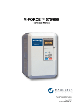
Low Voltage Harness Part Numbers
Type Use with Motor
18 in.
long
36 in.
long
9-pin
318003, 318004, 318013,
319356, 319357, 320587,
320588, 320589, 320590,
328128, 328129, 328130,
328131, 328132, 328133,
328173, 328174, 328178,
328179
385821
(0-10 VDC
only)
386518
(0-5 VCD
and
0-10V DC
compatible)
385822
(0-10 VDC
only)
386519
(0-5 VCD
and
0-10V DC
compatible)
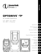
NOTE
The 9-pin connector on the motor contains 6 wires.
The yellow, orange, red and white wires are used for
external control. The other two wires are used for
factory initialization and programming.
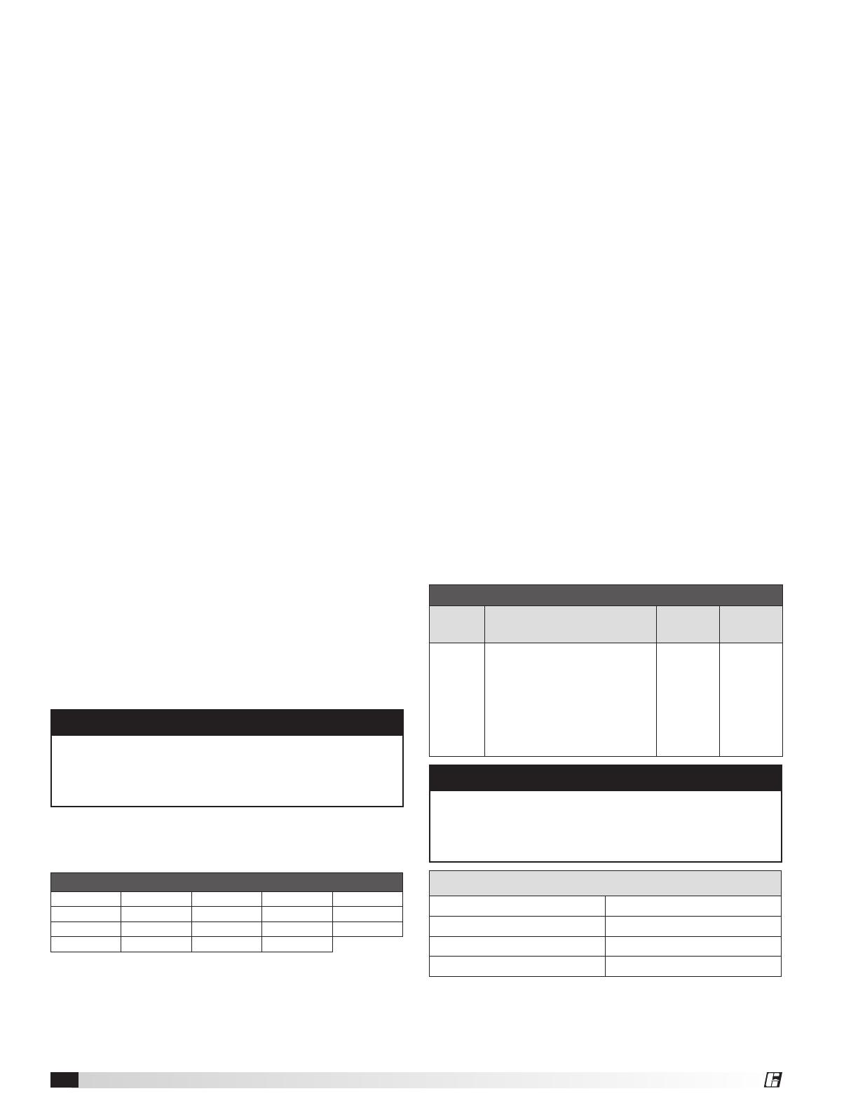
0-10V Analog Input Connection
Red + 0-10 VDC
White Common
Green +0-5 VDC Signal
Black 5 VDC Supply
Troubleshooting
Motor does not operate
1. Verify the motor is wired correctly and all connections
are secure.
Factory Mounted Transformer (Fig. 1, page 2)
A factory mounted transformer is available to supply
24 VDC power to the motor when the 0-10V signal
is by others. This transformer has the capability to
power a remote device if desired. The power available
to a remote device is 400mA at 24 VDC. If the remote
device is powered by a different source, connect the
analog output to the 0-10V and COM terminals of the
transformer. This will pass the signal through to the
motor.
WARNING
Do not connect an external 24V supply to the
transformer's control terminal labeled 24V. If the
external device providing the 0-10V signal is powered
elsewhere, this terminal can remain unused.
Troubleshooting
Motor does not operate
1. Check all wiring connections to ensure they are
correct and secure.
2. Verify that all voltages are present at the motor,
including 24V and 0-10 VDC, if applicable.
3. Make sure that the fan wheel will rotate freely and
there are no foreign objects in the wheel. If fan wheel
does not rotate freely, disconnect power from the
motor and adjust the wheel or housing until the
wheel can freely rotate. Apply power and the motor
should restart.
4. If motor has both the dial on the motor and 0-10VDC
control option, control wiring issues can be tested
by disconnecting the control wires from the motor.
The motor should then operate using the dial on the
motor for speed control.
Motor will not reach maximum speed
1. Make sure dial is rotated full clockwise, if applicable.
2. Make sure motor is receiving 10 VDC, if applicable.
3. There are some motor/fan combinations
where the motor may not reach nameplate
RPM. See Max RPM table on page 11 for the
maximum motor speed for your application.
Motor part numbers 318003, 318004 – The motor is
prewired at the factory and cannot be changed inside
the motor. Connect single-phase power at the voltage
listed on the nameplate.
Motor part numbers 318013, 319356, 319357, 320587,
320588, 320589, 320590, 328128, 328129, 328130,
328131, 328132, 328133, 328173, 328174, 328178,
and 328179 – The motor is prewired at the factory and
can operate on 115v up to 277v. Operating voltage is
changed via voltage red jumper wire.
Voltage jumper – For 115v the red jumper wire on
the side of the motor must be connected (closed).
For 208v-277v operation the red jumper must be
disconnected (open). If disconnected, red jumper
wire has 120 VAC potential. Ensure leads are capped/
covered.
Dial on Motor – A potentiometer (PN 385806) can
be plugged into the 9-pin connector of the motor. To
increase speed, rotate the dial clockwise. To decrease
speed, rotate the dial counterclockwise.
0-10 VDC Signal – From 0-1.9V, the motor will be off,
and will operate in the 2-10V range. A low voltage
wiring harness is needed to supply the 0-10V signal to
the motor. The harness is available from the factory if
conversion is necessary.
0-5 VDC Signal – From 0-0.9V, the motor will be off
and will operate in the 1-5V range. A low voltage
wiring harness is needed to supply the 0-5V signal to
the motor. The harness is available from the factory if
conversion is necessary.
Vari-Green Motor and Controls4