Miniature Aircraft USA X-Cell Furion 450 Assembly Manual
- Category
- Toys & accessories
- Type
- Assembly Manual


X-Cell Furion 450 Assembly Manual
Page 2 of 89 Copyright Miniature Aircraft USA Created: 8/27/2008
This document may not be distributed without permission of Miniature Aircraft USA
For More Information contact:
Miniature Aircraft USA
31713 Long Acres Drive
Sorrento, FL 32776 USA
Phone 352-383-3201
Fax 352-383-3204
Email: [email protected]

X-Cell Furion 450 Assembly Manual
Created: 8/27/2008 Copyright Miniature Aircraft USA Page 3 of 89
This document may not be distributed without permission of Miniature Aircraft USA
Table of Contents
REVISIONS TO THIS MANUAL................................................................................................................................................................................5
ERRATA.........................................................................................................................................................................................................................5
I. KIT INTRODUCTION ..............................................................................................................................................................................................6
R/C HELICOPTER SAFETY..............................................................................................................................................................................................6
GUIDELINES FOR SAFE R/C HELICOPTER FLIGHT............................................................................................................................................................6
X-CELL LIMITED WARRANTY ......................................................................................................................................................................................7
WARRANTY PROCEDURES..............................................................................................................................................................................................7
X-CELL FURION 450 WARRANTY REGISTRATION...........................................................................................................................................................7
II. KIT PREREQUISITES ............................................................................................................................................................................................8
SUPPLIES NEEDED FOR ASSEMBLY.................................................................................................................................................................................8
Adhesives Used........................................................................................................................................................................................................8
TOOLS NEEDED FOR ASSEMBLY.....................................................................................................................................................................................9
ADDITIONAL COMPONENTS NEEDED (AS SHOWN OR COMPATIBLE).................................................................................................................................9
DOCUMENTATION........................................................................................................................................................................................................10
III. KIT ASSEMBLY PROCESS................................................................................................................................................................................11
ASSEMBLY TIPS...........................................................................................................................................................................................................11
FASTENER GUIDE ........................................................................................................................................................................................................11
ASSEMBLY COMPONENTS – UNBAGGED PARTS ............................................................................................................................................................13
LOCATE CARBON FIBER PARTS BAG............................................................................................................................................................................14
Carbon Fiber Parts - Bag #1.................................................................................................................................................................................14
ASSEMBLY STEP #1 – CHASSIS...............................................................................................................................................................................15
1A) Frame Components - Bags #2A, #2B, #2 Hardware.......................................................................................................................................15
1A.1 - Assemble Tail Boom Clamp/Pulleys........................................................................................................................................................................16
1B.1 - Assemble Left Frame Components .........................................................................................................................................................................18
1C.1 – Install Right Frame/Landing Gear ..........................................................................................................................................................................21
1D.1 – Install Pitch/Aileron Servos ......................................................................................................................................................................................23
ASSEMBLY STEP #2 – PRIMARY DRIVE ...................................................................................................................................................................24
2A) Drive Train Components - Bag #3A, #3 Hardware.........................................................................................................................................24
2A.1 - Assemble T/R Pulley .....................................................................................................................................................................................................25
2B.1 - Assemble Main Gear .....................................................................................................................................................................................................26
2C.1 – Install Drive System ....................................................................................................................................................................................................27
2D.1 – Install Motor....................................................................................................................................................................................................................28
LOCATE LONG PARTS BAG ..........................................................................................................................................................................................29
Long Parts - Bag #4...............................................................................................................................................................................................29
ASSEMBLY STEP #3 – TAIL ROTOR/TAIL BOOM.....................................................................................................................................................30
3A) Tail Rotor Components - Bag #5A, 5B, 5C, #5 Hardware..............................................................................................................................30
3A.1 - Assemble T/R Fin ...........................................................................................................................................................................................................31
3A.2 – Assemble/Install T/R Bellcrank................................................................................................................................................................................32
3A.3 – Assemble/Install Tail Boom ......................................................................................................................................................................................33
3A.4 – Assemble T/R Transmission......................................................................................................................................................................................34
3A.5 – Set T/R Belt Tension ....................................................................................................................................................................................................35
3A.6 – Assemble T/R Pitch Change Mechanism ..............................................................................................................................................................36
3A.7 – Assemble T/R Hub ........................................................................................................................................................................................................38
3A.8 – Install T/R Pitch Change Mechanism.....................................................................................................................................................................40
3A.9 – Install Tail Rotor Assembly........................................................................................................................................................................................40
3B) Tail Rotor Control - Bag #6A, #6 Hardware...................................................................................................................................................41
3B.1 Install T/R Servo................................................................................................................................................................................................................41
3B.2 Assemble T/R Pushrod ....................................................................................................................................................................................................43
3B.3 Assemble/Install Tail Boom Supports.......................................................................................................................................................................44
ASSEMBLY STEP #4 – CONTROL SYSTEMS .............................................................................................................................................................46
4A) Electronics Installation/Main Control Components - Bag #7A, #7B, #7 Hardware .......................................................................................46
4A.1 Install Elevator Servo.............................................................................................................................................................................................47
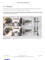
4A.2 Install Electronics.....................................................................................................................................................................................................47
4A.3 Install Servo Arms...................................................................................................................................................................................................50
4A.4 Assemble Cyclic Control Rods.............................................................................................................................................................................51

X-Cell Furion 450 Assembly Manual
Page 4 of 89 Copyright Miniature Aircraft USA Created: 8/27/2008
This document may not be distributed without permission of Miniature Aircraft USA
4A.5 Assemble Swashplate.............................................................................................................................................................................................52
4A.6 Install Swashplate/Control Rods .......................................................................................................................................................................53
4A.7 Assemble Washout Mixer......................................................................................................................................................................................54
ASSEMBLY STEP #5 – ROTOR HEAD .......................................................................................................................................................................56
5A) Rotor Head Components - Bag #8A, #8B, #8C, #8 Hardware........................................................................................................................56
5A.1 Assemble Bell Mixers..............................................................................................................................................................................................57
5A.2 Assemble Main Rotor Block..................................................................................................................................................................................58
5A.3 Assemble Main Blade Grips..................................................................................................................................................................................59
5A.4 Assemble Flybar Components ............................................................................................................................................................................62
5A.5 Install Rotor Head....................................................................................................................................................................................................65
5A.6 Assemble/Install Rotor Head Control Rods ...................................................................................................................................................67
ASSEMBLY STEP #6 – COMPLETE MODEL ASSEMBLY .............................................................................................................................................68
6A) Canopy Components - Bag #9A, #9 Hardware...............................................................................................................................................68
6A.1 Assemble/Install Canopy ......................................................................................................................................................................................68
6A.2 Install Decals .............................................................................................................................................................................................................70
6A.3 Install Rotor Blades.................................................................................................................................................................................................71
6A.4 Install Battery............................................................................................................................................................................................................71
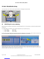
IV. BASIC MODEL/RADIO SETUP .........................................................................................................................................................................72
A) INITIAL SETUP FOR SERVO CENTERING ............................................................................................................................................................72
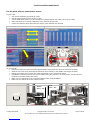
B) SETUP FOR COLLECTIVE, CYCLIC AND RUDDER ..............................................................................................................................................75
B.1 Setting Swashplate Movements.................................................................................................................................................................75
B.1.1 Collective Movements.........................................................................................................................................................................................................75
B.1.2 Cyclic Movements...............................................................................................................................................................................................................77
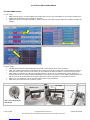
B.1.3 Swashplate – Center Level..................................................................................................................................................................................................78
B.1.3 Swashplate – Extreme Throws Level..................................................................................................................................................................................79
B.2 Setting Blade Limits..................................................................................................................................................................................80
B.2.1 Install Flybar Lock/Blade Gauge.........................................................................................................................................................................................80
B.2.2 Pitch Curve Setup ................................................................................................................................................................................................................80
B.2.3 Cyclic Throw Setup.............................................................................................................................................................................................................82
B.3 Rudder Setup ............................................................................................................................................................................................83
B.4 Exponential...............................................................................................................................................................................................84
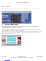
C) SETUP FOR SPEED CONTROLLER .....................................................................................................................................................................84
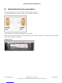
D) BATTERY/MOTOR/PINION RECOMMENDATIONS..............................................................................................................................................85
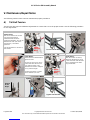
V. MAINTENANCE/REPAIR NOTES......................................................................................................................................................................86
A) TAIL BELT TENSION .......................................................................................................................................................................................86
B) T/R GRIP/BEARING/HUB REMOVAL................................................................................................................................................................87
C) MAIN BLADE GRIP/BLADE AXLE REMOVAL ...................................................................................................................................................87

X-Cell Furion 450 Assembly Manual
Created: 8/27/2008 Copyright Miniature Aircraft USA Page 5 of 89
This document may not be distributed without permission of Miniature Aircraft USA
Revisions to this Manual
R1.0
• 07/01/08 – Initial Release
R1.1
• 07/05/08 – 3B.1.a added note
4A.5.c changed part #130-076 to the correct #130-074
4A.5.g changed part #130-016 to the correct #130-070
4A.7.j-k changed part #130-150 to the correct #130-030
• 07/12/08 - IV.C added warning about throttle reversing
4A.1.d added warning about t/r belt routing
• 08/10/08 - 4A.2.f-h renumbered part #130-450 to #130-460
For the most current version of this manual, please refer to www.miniatureaircraftusa.com, visit the
Furion helicopter kit and download the assembly manual
Errata
R1.0
• The finish on some metal parts and fasteners in the production kit may differ from that shown in
this manual. This will not result in any change to the assembly process
• Some square head socket bolts shown in the manual were replaced with button head socket bolts
in the production kit. The threaded dimensions are identical.

X-Cell Furion 450 Assembly Manual
Page 6 of 89 Copyright Miniature Aircraft USA Created: 8/27/2008
This document may not be distributed without permission of Miniature Aircraft USA
I. Kit Introduction
R/C Helicopter Safety
A radio controlled model helicopter is a technically complex device that must be built and operated with
care. It is also a fascinating and challenging part of the R/C sport, the mastery of which is very rewarding.
A model helicopter must be built exactly in accordance with the building instructions. The kit manufacturer
has spent much time and effort refining his product to make it reliable in operation and easy to build. The
essentially bolt together construction can proceed quite rapidly, giving the builder a strong sense of
accomplishment that encourages hasty progress from one construction phase to the next, so that the
completed model can be more quickly seen and enjoyed. It is essential to recognize and guard against this
tendency. Follow building instructions exactly. Vibration and stress levels are high and all fasteners and
attachments must be secure for safe operation.
Note that this is the first use of the word SAFETY in these comments. Previously the kit manufacturer’s
efforts to ensure reliable operation were mentioned. That is ALL that he can do. Safe operation is the
responsibility of the builder/flyer and starts with careful construction and continues with selection and
installation of reliable radio equipment and engine.
The need for safety is nowhere greater than at the flying field. A number of guidelines for safe flight have
been developed by experienced flyers and are set down here. It is urged that they be read, understood
and followed.
Guidelines for Safe R/C Helicopter Flight
• Fly only at approved flying fields and obey field regulations.
• Follow frequency control procedures. Interference can be dangerous to all.
• Know your radio. Check all transmitter functions before each flight.
• Be aware that rotating blades are very dangerous and can cause serious injury.
• Never fly near or above spectators or other modelers.
• If a beginner, get help trimming the model first and flight training later.
• Don’t “track” the main blades by holding the tail boom. This is a temptation to builders who cannot
hover yet and is very dangerous.
• Follow all recommended maintenance procedures for model, radio and engine.
WARNING!
This helicopter is not a toy, but a complex flying machine that must be assembled with care by a
responsible individual. Failure to exert care in assembly, or radio or accessory installation, may result in a
model incapable of safe flight or ground operation. Rotating components are an ever present danger and
source of injury to operators and spectators. Since the manufacturer and his agents have no control over
the proper assembly and operation of his products, no responsibility or liability can be assumed for their
use.

X-Cell Furion 450 Assembly Manual
Created: 8/27/2008 Copyright Miniature Aircraft USA Page 7 of 89
This document may not be distributed without permission of Miniature Aircraft USA
X-CELL Limited Warranty
The warranty covers defects in material or workmanship or missing components to the original purchaser
for 30 days from the date of purchase. Miniature Aircraft, USA will replace or repair, at our discretion, the
defective or missing component. Defective components must be returned to us prior to replacement.
Any part, which has been improperly installed, abused, crash damaged or altered by unauthorized
agencies, is not covered. Under no circumstances will the buyer be entitled to consequential or incidental
damages. The components used in this kit are made form special materials designed for special
applications and design strengths. We recommend that all replacement parts be original parts
manufactured by Miniature Aircraft, USA, to ensure proper and safe operation of your model. Any part
used which was manufactured by any firm other than Miniature Aircraft, USA, VOIDS all warrantees of this
product by Miniature Aircraft, USA.
Warranty Procedures
Mail all warranty information within 15 days of original purchase date. If service is required, send the
component in question (if not missing) together with a photocopy of your bill of sale and an accurate
description of the problem and part. Ship components fully insured and prepaid. Miniature Aircraft, USA is
not responsible for any shipping damages. We will, at our discretion, notify you of any costs involved, or
ship it COD. You are required to pay all postage, shipping and insurance charges.
X-Cell Furion 450 Warranty Registration
Please print or type, filling in the information listed below and mail immediately
Model No:____________ Serial No:____________ Price paid:___________________
Owners name:______________________________ Age_______________________
Address:____________________________________ Phone:___________________
City:_______________________ State:____________ Zip:___________________
Purchased from: ________________________________________________________
Dealer’s address ________________________________________________________
Comments: ____________________________________________________________
______________________________________________________________________
_________________________________________________________________________
_________________________________________________________________________
_________________________________________________________________________
MINIATURE AIRCRAFT USA
31713 Long Acres Drive
Sorrento, FL 32776 USA
Phone (352) 383-3201
FAX (352) 383-3204

X-Cell Furion 450 Assembly Manual
Page 8 of 89 Copyright Miniature Aircraft USA Created: 8/27/2008
This document may not be distributed without permission of Miniature Aircraft USA
II. Kit Prerequisites
In order to assemble this kit, you will need a number of additional supplies and tools to ensure the best
final result. They are as follows:
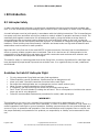
Supplies Needed for Assembly
Blue Thread
Lock Green
Thread Lock Oil Grease
Adhesives Used
Slow
Cyanoacrylate

X-Cell Furion 450 Assembly Manual
Created: 8/27/2008 Copyright Miniature Aircraft USA Page 9 of 89
This document may not be distributed without permission of Miniature Aircraft USA
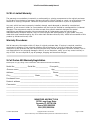
Tools Needed for Assembly
1.5mm allen driver
2.5mm allen driver
M5 Nut Driver
Needle Nose Pliers
Flat Screwdriver 2.5mm
Phillips Screwdriver #0
Phillips Screwdriver #1
Ball Link Pliers
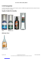
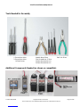
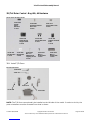
Additional Components Needed (as shown or compatible)
Gyro – Heading Hold
Gyro Servo
1 each
Cyclic
Servos
3
each
Battery
LiPo 2500 mah
3S1P

X-Cell Furion 450 Assembly Manual
Page 10 of 89 Copyright Miniature Aircraft USA Created: 8/27/2008
This document may not be distributed without permission of Miniature Aircraft USA
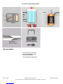
Documentation
The most recent version of all
of the documentation can be
found on the website:
www.miniatureaircraftusa.com
Receiver
Minimum
45 amp
ESC
With
BEC
Or a
separate
BEC is
required
Motor
Rotor Blades
SAB 320-325mm Paddle/Pitch gauge tools

X-Cell Furion 450 Assembly Manual
Created: 8/27/2008 Copyright Miniature Aircraft USA Page 11 of 89
This document may not be distributed without permission of Miniature Aircraft USA
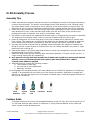
III. Kit Assembly Process
Assembly Tips
1. Please note that this assembly manual consists of a photographic journal of the steps necessary to
construct this helicopter. The builder is encouraged to pay close attention to the "building notes"
and other details noted in the pictures and to carefully review all the photo’s in a given step. The
placement of a given part may be better understood when viewing another view of the assembly.
2. Follow the order of assembly. The instructions have been organized into major sections and have
been developed in such a way that each step builds upon the work done in the previous step.
Changing the order of assembly may result in unnecessary steps
3. The photos in this manual are organized within each step to correspond with the order of assembly.
The sequence of the photos within a step is from top to bottom and from left to right.
4. Clean all metal parts: All of the steel parts in this kit are coated with a lubricant to prevent them
from rusting. This coating can interfere with the adhesives and thread locks needed for assembly.
Use a solvent such as alcohol or acetone to clean the various metal parts, especially threads
5. Use only the formula of thread lock as indicated. Model helicopters are subject to vibration and
failing to use the correct formula of thread lock on any non-locking assembly may result in a part
becoming loose or falling off.
6. Sand sharp edges on any frame plate that Velcro® or wires may rub against to prevent them from
being damaged over time by vibration
7. Make sure every bearing runs smoothly after component assembly. If it does not find out why. A
rough running bearing will fail prematurely.
8. As a general rule any bolt that threads into a metal part should have thread lock applied
and any screw or bolt that threads into a plastic part should have thick (ONLY)
Cyanoacrylate adhesive applied
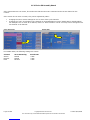
9. Assembly sections contain the following content:
a. The contents of each bag
b. An overview of part relationships
c. Assembly overview
10. Photographs will contain assembly icons that indicate use of thread lock, adhesive or lubricant as
needed. If an assembly has more than one of the same part number, application of thread lock,
adhesive or lubricant will apply to all of the same numbered parts in that photograph Examples of
the icons are as follows:
Thick
Adhesive
Blue
Thread
Lock
Green
Thread
Lock
Lubricant
Grease
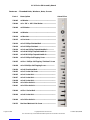
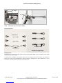
Fastener Guide
This page contains a list of all of the threaded fasteners in this kit. They will print at actual size. If
it is not clear what the part number of a fastener is, simply find the fastener on the chart and
match its part number and description

X-Cell Furion 450 Assembly Manual
Page 12 of 89 Copyright Miniature Aircraft USA Created: 8/27/2008
This document may not be distributed without permission of Miniature Aircraft USA
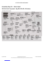
Fasteners – Threaded Bolts, Washers, Nuts, Screws
Part # Description Actual Size
130-002 m2 Washer -------------------------------------------------------
130-004 m2 x .150" x .020" Shim Washer --------------------------
130-006 m2.5 Washer -----------------------------------------------------
130-008 m3 Washer -------------------------------------------------------
130-010 m2 Hex Nut -------------------------------------------------------
130-012 m3 Locknuts -----------------------------------------------------
130-014 m2 x 3 Phillips Flat Head Bolt -----------------------------
130-016 m2 x 4 Phillips Flat Head ------------------------------------
130-019 m2 x 6 mm Phillips Tapered Head Bolt -------------
130-020 m2 x 8.00 Phillips Tapered Head Bolt ------------------
130-022 m2 x 8.50 Phillips Tapered Head Bolt ------------------
130-024 m2 x 3 Phillips Self-Tapping Screw ---------------------
130-025 m2.2 x 6 Phillips Self-Tapping "Flat Head" Screw
130-028 m2 x 13 Phillips Self-Tapping Screw -----------------
130-030 m2 x 8 Shouldered Bolt --------------------------------------
130-032 m3 x 3 Socket Set Screw ------------------------------------
130-035 m2 x 4 Socket Bolt --------------------------------------------
130-037 m2 x 6 Socket Bolt --------------------------------------------
130-038 m2 x 8 Socket Bolt --------------------------------------------
130-040 m2 x 10 Socket Bolt -------------------------------------------
130-041 m2 x 12 Socket Bolt -------------------------------------------
130-044 m2.5 x 6 Socket Bolt ------------------------------------------
130-046 m3 x 8 Socket Bolt --------------------------------------------
130-049 m3 x 14 Socket Bolt -------------------------------------------
130-153 Machined Washout Link Screw ---------------------------

X-Cell Furion 450 Assembly Manual
Created: 8/27/2008 Copyright Miniature Aircraft USA Page 13 of 89
This document may not be distributed without permission of Miniature Aircraft USA
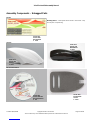
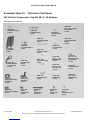
Assembly Components – Unbagged Parts
Decals
Building Notes – These parts will be found in the kit box. They
are not part of a parts bag.
Canopy
Kit Documentation
#130-251
Furion 450
Canopy
1 each
#130-253
Furion 450
Decal Sheet
1 each
#130-252
Furion 450
Windshield
1 each
#130-405
Furion 450 Kit
Documentation
1 CD
#130-400
Foam Blade
Guard
1 each

X-Cell Furion 450 Assembly Manual
Page 14 of 89 Copyright Miniature Aircraft USA Created: 8/27/2008
This document may not be distributed without permission of Miniature Aircraft USA
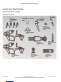
Locate Carbon Fiber Parts Bag
Carbon Fiber Parts - Bag #1
This Bag Should Contain:
#130-242
C/F Main Frames
2 each
#130-122
C/F Main Blade
Mounting Plates
4 each
#130-243
Battery Plate
1 each
#130-239
C/F Anti-rotation
Guide
1 each
#130-280
C/F Rudder
Servo
Plate
1 each
#130-163
C/F Swashplate Retaining
Ring
1 each
#130-208
C/F Gyro Plate
1 each
#130-225
C/F Base Plate
1 each
#130-295
C/F Horizontal Fin
1 each
#130-358
C/F Inner Tail
Plate w/bearing
1 each
#130-360
C/F Tail Fin
w/bearing
1 each

X-Cell Furion 450 Assembly Manual
Created: 8/27/2008 Copyright Miniature Aircraft USA Page 15 of 89
This document may not be distributed without permission of Miniature Aircraft USA
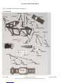
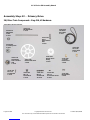
Assembly Step #1 – Chassis
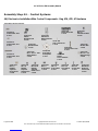
1A) Frame Components - Bags #2A, #2B, #2 Hardware
These Bags Should Contain:
#130-245
Plastic Landing
Gear
1 each
#130-052
M2 x 5 x 2.5
Ball Bearings
2 each
#130-205
Plastic Boom Mounts
2 each
#130-207
Knurled Threaded
Spacers
4 each
#130-210
Tail Rotor
Belt Pulleys
2 each
#130-215
Pulley Spacers
2 each
#130-236
Upper Mainshaft Block
w/Bearing
1 each
#130-238
Lower Servo Mount
1 each
#130-237
Upper Servo Mount
1 each
#130-241
Lower Mainshaft Block
w/Bearing
1 each
#130-220
Canopy
Mounts
2 each
#130-230
Frame Spacers
5 each
#130-002
M2 Washers
6 each
#130-016
M2 x 4
Phillips Flat Head Bolt
4 each
#130-025
M2 x 6.5 Phillips
Screw
2 each
#130-038
M2 x 8
Socket Bolt
6 each
#130-037
M2 x 6
Socket Bolt
10 each
#130-035
M2 x 4
Socket Bolt
40 each

X-Cell Furion 450 Assembly Manual
Page 16 of 89 Copyright Miniature Aircraft USA Created: 8/27/2008
This document may not be distributed without permission of Miniature Aircraft USA
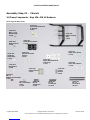
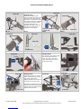
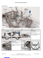
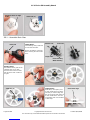
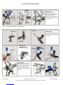
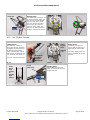
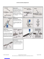
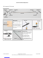
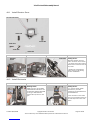
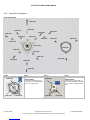
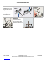
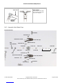
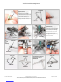
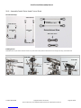
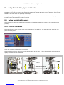
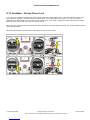
1A.1 - Assemble Tail Boom Clamp/Pulleys
Parts Relationship
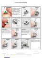
1A.1.a 1A.1.b 1A.1.c 1A.1.d
1A.1.e 1A.1.f 1A.1.g 1A.1.h
Building Notes:
Don’t push the two halves
completely together, leave a
small gap as the tail boom will
be inserted into this later
Note the location of the
protrusions on the blocks
Building Notes:
Note when building the gyro
plate that one side has a milled
section on it. The pulleys mount
on the side of the plate with the
milled flat.
#130-205
#130-205
#130-207(4)
#130-208
#130-025
#130-025
#130-035
#130-035
#130-215
#130-210
#130-052
#130-037
#130-205
#130-207(4) Knurled End
Front
#130-205
Push halves together
Align posts and holes
Note protrusions
#130-208
#130-035 #130-215
Milled Flat

X-Cell Furion 450 Assembly Manual
Created: 8/27/2008 Copyright Miniature Aircraft USA Page 17 of 89
This document may not be distributed without permission of Miniature Aircraft USA
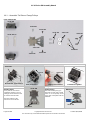
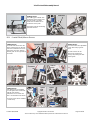
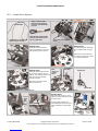
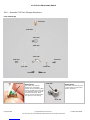
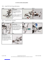
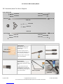
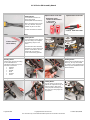
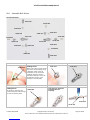
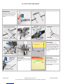
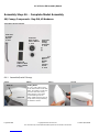
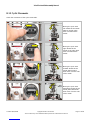
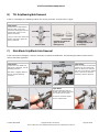
1A.1.i 1A.1.j 1A.1.k 1A.1.l
Building Notes:
Apply a thin coat of green thread
lock on the bearings using a
toothpick. Place a drop of
thread lock on the end of the
toothpick and then smear it
around the bearings. Wipe away
any excess and be careful not to
get any in the bearing
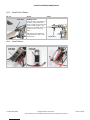
1A.1.m 1A.1.n 1A.1.o 1A.1.p
Building Notes:
Note that each pulley has a
flanged side.
Use an allen driver to push a
bearing into each pulley and
seat against the flange
Set aside allow the thread lock
to dry before installing the
pulleys.
Building Notes:
Do not over tighten bolts. Make
sure pulleys spin freely
Be careful not to get any thread
lock in the bearings.
1A.1.q 1A.1.r
#1
30
-
03
7
#130-052
#130-210
Note
Flange
Inside
#130-052
Use allen driver to
seat bearing against
inside flan
g
e in
p
ulle
y
#130-037
#130-025

X-Cell Furion 450 Assembly Manual
Page 18 of 89 Copyright Miniature Aircraft USA Created: 8/27/2008
This document may not be distributed without permission of Miniature Aircraft USA
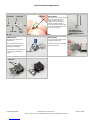
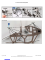
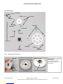
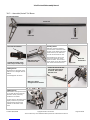
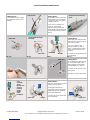
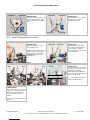
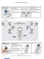
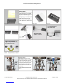
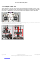
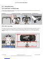
1B.1 - Assemble Left Frame Components
Parts Relationship
#130-220
#130-035
#130-035
#130-242
#130-243
#130-230
#130-035
#130-016
#130-037
#130-236
#130-239
#130-241
#130-225
#130-230
#130-035 #130-035
#130-035
#130-237
#130-002
#130-037
#130-238
#130-016
#130-002
#130-035
#130-035
#130-037

X-Cell Furion 450 Assembly Manual
Created: 8/27/2008 Copyright Miniature Aircraft USA Page 19 of 89
This document may not be distributed without permission of Miniature Aircraft USA
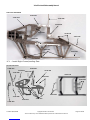
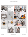
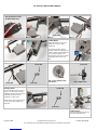
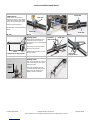
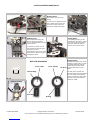
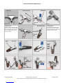
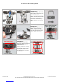
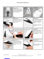
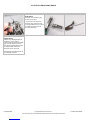
1B.1.a 1B.1.b 1B.1.c 1B.1.d
Building Notes:
Note that the bottom plate
contains 4 PEM nuts. One side of
each PEM nut is wider than the
other side. The side of the lower
plate which shows the wide PEM
is the TOP of the plate. Install
the frame spacers on the
BOTTOM of the plate as shown.
The flat side of the spacer is
against the carbon plate.
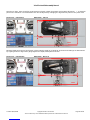
1B.1.e 1B.1.f 1B.1.g 1B.1.h
1B.1.i 1B.1.j 1B.1.k 1B.1.l
Building Notes:
T
he tail boom block plate installs
into the left frame from the
inside. The tab on the lower
pulley plate slides into the left
frame tab as shown
1B.1.m 1B.1.n 1B.1.o 1B.1.p
Building Notes:
Install frame blocks on inside of
frame using bolts seen on bolt
map which follows while
applying thread lock (except on
the lower servo mount bolts)
Note that the protrusions on the
bearing blocks faces downwards
and the upper and lower bearing
flanges face each other.
#130-230
#130-225
#130-035
#130
-
236
#1
30
-22
0
Insert tab into
frame slot
#1
30
-
035
#130-242
#130
-
016
#130-239
#130-238
#130-016
(
2
)
#130-230
#130-035
#130-016
#130-243
Wide side of PEM nuts on
opposite side
#130
-
035
Slot/Tab #130-241
#130-238
#130-035
#130-002

X-Cell Furion 450 Assembly Manual
Page 20 of 89 Copyright Miniature Aircraft USA Created: 8/27/2008
This document may not be distributed without permission of Miniature Aircraft USA
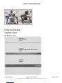
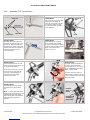
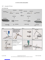
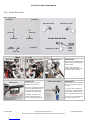
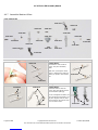
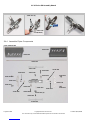
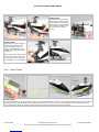
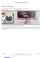
1B.1.q 1B.1.r 1B.1.s 1B.1.t
Left Frame Map
#130-035
#130-035
#130-035
Do Not
Tighten this
bolt yet
#130-035
Do Not
Tighten
Yet
#130-225
#130-243
Protrusions
face down
#130-035
#130-002
No Bolt
Page is loading ...
Page is loading ...
Page is loading ...
Page is loading ...
Page is loading ...
Page is loading ...
Page is loading ...
Page is loading ...
Page is loading ...
Page is loading ...
Page is loading ...
Page is loading ...
Page is loading ...
Page is loading ...
Page is loading ...
Page is loading ...
Page is loading ...
Page is loading ...
Page is loading ...
Page is loading ...
Page is loading ...
Page is loading ...
Page is loading ...
Page is loading ...
Page is loading ...
Page is loading ...
Page is loading ...
Page is loading ...
Page is loading ...
Page is loading ...
Page is loading ...
Page is loading ...
Page is loading ...
Page is loading ...
Page is loading ...
Page is loading ...
Page is loading ...
Page is loading ...
Page is loading ...
Page is loading ...
Page is loading ...
Page is loading ...
Page is loading ...
Page is loading ...
Page is loading ...
Page is loading ...
Page is loading ...
Page is loading ...
Page is loading ...
Page is loading ...
Page is loading ...
Page is loading ...
Page is loading ...
Page is loading ...
Page is loading ...
Page is loading ...
Page is loading ...
Page is loading ...
Page is loading ...
Page is loading ...
Page is loading ...
Page is loading ...
Page is loading ...
Page is loading ...
Page is loading ...
Page is loading ...
Page is loading ...
Page is loading ...
Page is loading ...
-
 1
1
-
 2
2
-
 3
3
-
 4
4
-
 5
5
-
 6
6
-
 7
7
-
 8
8
-
 9
9
-
 10
10
-
 11
11
-
 12
12
-
 13
13
-
 14
14
-
 15
15
-
 16
16
-
 17
17
-
 18
18
-
 19
19
-
 20
20
-
 21
21
-
 22
22
-
 23
23
-
 24
24
-
 25
25
-
 26
26
-
 27
27
-
 28
28
-
 29
29
-
 30
30
-
 31
31
-
 32
32
-
 33
33
-
 34
34
-
 35
35
-
 36
36
-
 37
37
-
 38
38
-
 39
39
-
 40
40
-
 41
41
-
 42
42
-
 43
43
-
 44
44
-
 45
45
-
 46
46
-
 47
47
-
 48
48
-
 49
49
-
 50
50
-
 51
51
-
 52
52
-
 53
53
-
 54
54
-
 55
55
-
 56
56
-
 57
57
-
 58
58
-
 59
59
-
 60
60
-
 61
61
-
 62
62
-
 63
63
-
 64
64
-
 65
65
-
 66
66
-
 67
67
-
 68
68
-
 69
69
-
 70
70
-
 71
71
-
 72
72
-
 73
73
-
 74
74
-
 75
75
-
 76
76
-
 77
77
-
 78
78
-
 79
79
-
 80
80
-
 81
81
-
 82
82
-
 83
83
-
 84
84
-
 85
85
-
 86
86
-
 87
87
-
 88
88
-
 89
89


Miniature Aircraft USA X-Cell Furion 450 Assembly Manual
- Category
- Toys & accessories
- Type
- Assembly Manual
Ask a question and I''ll find the answer in the document
Finding information in a document is now easier with AI
Related papers

Other documents
-
Kmart 43313099 User manual
-
Lego 75330 User manual
-
Game Of Bricks Light Kit User manual
-
-
Game Of Bricks 76397 User manual
-
GAME OF BAICKS 75304 User manual
-
 XCell Fury Extreme Assembly Manual
-
 RJX Hobby X-TREME 50 Assembly Instructions Manual
-
Sharper Image Frost Free Windshield Covers Operating instructions
-
Infinity S601 Profile User manual

