Page is loading ...

Page 1
9/15
BH20030, Rev 10

Page 2
Model DA66B is a hydraulic surge brake actuator for trailers with two or four wheels.
When brakes are applied on the towing vehicle, forward inertia of trailer toward tow-
ing vehicle applies brakes on trailer in direct relation to manner brakes are applied
on towing vehicle. Brake towing vehicle hard and brakes on trailer are applied hard.
Master cylinder push rod spring assembly protects system from hydraulic pressure
overload.
DEMCO MODEL DA66B ACTUATOR
• Review following instructions before installation and use of hydraulic brake
actuator.
• Dealers or distributors must review these instructions with ultimate user.
• Failure to follow these instructions, or failure to properly maintain braking
system after installation, can result in loss of braking action.
WARNING: To Prevent Serious Injury or Death
Table of Contents
General information ............................................................................................................. 2
Safety, Signal Words ........................................................................................................... 3
Equipment Safety Guidelines .............................................................................................. 3
Remember .......................................................................................................................... 3
Safety Sign Locations ......................................................................................................... 4
Safety Sign Care ................................................................................................................. 4
Before Operation ................................................................................................................. 5
During Operation ................................................................................................................. 5
Following Operation ............................................................................................................ 6
Highway and Transport Operations ..................................................................................... 6
Performing Maintenance ....................................................................................................6-7
Bolt Torque .......................................................................................................................... 7
DA66B Brake Actuator Parts Breakdown and Parts List ..................................................... 8
Repair Kit Parts List ............................................................................................................ 9
Actuator Installation and Maintenance .............................................................................10-11
Actuator Trouble Shooting Guide ....................................................................................... 11
WARRANTY POLICY & REGISTRATION
Go online to www.demco-products.com to review Demco warranty policies and register your Demco product.

Page 3
SAFETY
TAKE NOTE! THIS SAFETY ALERT SYMBOL FOUND THROUGHOUT THIS MANUAL IS USED TO CALL
YOUR ATTENTION TO INSTRUCTIONS INVOLVING YOUR PERSONAL SAFETY AND SAFETY OF
OTHERS. FAILURE TO FOLLOW THESE INSTRUCTIONS CAN RESULT IN INJURY OR DEATH.
THIS SYMBOL MEANS
ATTENTION
BECOME ALERT
YOUR SAFETY IS INVOLVED!
SIGNAL WORDS
Note use following signal words DANGER, WARNING, and
CAUTION with safety messages. Appropriate signal word
for each has been selected using following guidelines:
DANGER:
Indicates an imminently hazardous situation that, if not
avoided, will result in serious injury or death. This signal
word is to be limited to most extreme situations typically for
machine components which, for functional purposes, cannot
be guarded.
WARNING:
Indicates a potentially hazardous situation that, if not avoided,
could result in serious injury or death, and includes hazards
that are exposed when guards are removed. It may also be
used to alert against unsafe practices.
CAUTION:
Indicates a potentially hazardous situation that, if not avoided,
may result in minor or moderate injury. It may also be used
to alert against unsafe practices.
If you have questions not answered in this manual, require additional copies, or if your manual is damaged, please
contact your dealer or Demco, P.O. Box 189, 4010 320th Street, Boyden, IA 51234
ph: (712) 725-2311Toll Free: 1-800-543-3626 Fax: (712) 725-2380 http://www.demco-products.com
EQUIPMENT SAFETY GUIDELINES
Every year many accidents occur which could have been avoided by a few seconds of thought and a more careful
approach to handling equipment. You the operator, can avoid many accidents by observing and following precautions
in this section. To avoid personal injury, study the following precautions and insist those working with you, or you
yourself, follow them.
In order to provide a better view, certain illustrations in this manual may show an assembly with a safety shield removed.
However, equipment should never be operated in this condition. Keep all shields in place. If shield removal becomes
necessary for repairs, replace shield prior to use.
Replace any caution, warning, danger or instruction safety decal that is not readable or is missing. Location of such
decals is indicated in this booklet.
Do not attempt to operate this equipment under the influence of alcohol or drugs.
Review safety instructions with all users.
Operator should be a responsible adult. DO NOT ALLOW PERSONS TO OPERATE OR ASSEMBLE THIS UNIT
UNTIL THEY HAVE DEVELOPED A THOROUGH UNDERSTANDING OF SAFETY PRECAUTIONS AND HOW
IT WORKS.
Do not paint over, remove, or deface any safety signs or warning decals on your equipment. Observe all safety signs
and practice instructions on them.
Never exceed limits of a piece of machinery. If its ability to do a job, or to do so safely is in question-DON’T TRY IT.
REMEMBER
Your best assurance against accidents is a careful and responsible operator. If there is any portion of this manual
or function you do not understand, contact your local authorized dealer or manufacturer.

Page 4
SAFETY SIGN CARE
• Keepsafetysignscleanandlegibleatalltimes.
• Replacesafetysignsthataremissingorhavebecomeillegible.
• Replacementpartsthatdisplayedasafetysignshouldalsodisplaysafetysign.
• Safetysignsareavailablefromyourdistributor,dealerpartsdepartment,orfactory.
How to install safety signs:
• Besurethatinstallationareaiscleananddry.
• Decideonexactpositionbeforeyouremovebackingpaper.
• Removesmallestportionofsplitbackingpaper.
• Aligndecaloverspeciedareaandcarefullypresssmallportionwithexposedstickybackinginplace.
• Slowlypeelbackremainingpaperandcarefullysmoothremainingportionofdecalintoplace.
• Smallairpocketscanbepiercedwithapinandsmoothedoutusingpieceofdecalbackingpaper.
SAFETY SIGN LOCATIONS
Types of safety sign and locations on equipment are shown in illustration below. Good safety
requires that you familiarize yourself with various safety signs, type of warning, and area or
particular function related to that area, that requires your SAFETY AWARENESS.
This decal is located in the
position shown on both sides of
the actuator. The replacement
part number for two decals is
BH21004.
Preset
Fasteners
DO NOT adjust
without
factory
specifications.
Preset
Fasteners
DO NOT adjust
without
factory
specifications.
DRUM BRAKES
DISC BRAKES
ATTENTION
This brake actuator is
specially designed for
use with disc brakes
ONLY.
Any replacement of
this unit MUST be of
the same design.
REV 1 BD21001
ordered 01-22-01 with no changes
ordered 04-02-01 with no changes
ordered 10-02-02 with no changes
ordered 05-20-04 with no changes
ordered 09-20-04 with no changes
this file was ordered 03-03-05
this file was ordered 05-24-05
this file was ordered 08-09-05
this file was ordered 09-06-05
this decal was ordered 11-09-05
decal was ordered 11- 28-05
decal was ordered 02-20-06
decal was ordered 04-05-06
decal was ordered 06-12-06
this decal was ordered 08-07-06
ordered 09-27-06
ordered 11-06-07
ordered 07-08-08
This decal is located in the
position shown on both
sides of the actuator. The
replacement part number
for one decal is BD21001.

Page 5
BEFORE OPERATION:
• Carefullystudyandunderstandthismanual.
• Alwayswearprotectiveclothingandsubstantialshoes.
• Giveequipmentavisualinspectionforanyloosebolts,wornparts,orcrackedwelds,andmakenecessary
repairs. Follow maintenance safety instructions included in this manual.
• Besuretherearenotoolslyingonorinequipment.
• Donotuseequipmentuntilyouaresurethatareaisclear,especiallyaroundchildrenandanimals.
• Don’thurrylearningprocessortakeequipmentforgranted.Easeintoitandbecomefamiliarwithyournew
equipment.
• Practiceoperationofyourequipmentanditsattachments.Completelyfamiliarizeyourselfandotheroperators
with its operation before using.
• Makesurethatbrakesareevenlyadjusted.
• Makesuretowratingonvehicleishighenoughforwhatitistowing.
• Donotallowanyonetostandbetweentongueorhitchandtowingvehiclewhenbackinguptoequipment.
• Securelyattachtotowingvehicle.Useappropriatelysizedhitchballand/orhitchpinwithamechanicalretainer
and attach safety chains.
• Crisscrosschainsundertongueandsecuretodrawbarcage,mountingloops,orbumperframe.
DURING OPERATION
• SAFETY CHAINS If equipment is going to be transported on a public highway, safety chains should be
obtained and installed. Always follow state and local regulations regarding safety chains and auxiliary
lighting when towing equipment on a public highway. Be sure to check with local law enforcement
agencies for your own particular regulations. Only safety chains (not an elastic or nylon/plastic tow
straps) should be used to retain connection between towing and towed equipment in event of separation
of primary attaching system.
• Installsafetychainsbycrisscrossingchainsundertongueandsecuretodrawbarcage,mountingloops,or
bumper frame.
• When attaching the emergency cable Allow adequate slack to keep from activating brakes due to
interference from parts of the coupler or other attachments on the towing vehicle. Each vehicle tongue
configuration is different and therefore each should be handled individually to keep the routing free
from entanglements and securely attached to perform as designed in case of emergency disconnection
from the towing vehicle.
• Bewareofbystanders,PARTICULARLY CHILDREN! Always look around to make sure it is safe to start
engine of towing vehicle or move equipment. This is particularly important with higher noise levels, as you may
not hear people shouting.
• NO PASSENGERS ALLOWED- Do not carry passengers anywhere on or in equipment.
• Donotclean,lubricate,oradjustyourequipmentwhileitismoving.
• Whenhaltingoperation,evenperiodically,settowingvehiclesparkingbrake,shutoffengine,and remove the
ignition key.
• Beextracarefulwhenusingoninclines.
• MANEUVER TOWING UNIT AT SAFE SPEEDS.
• Avoidloosegravel,rocks,andholes,theycanbedangerousforequipmentoperationormovement.
• Allowforoveralllengthwhenmakingturns.
• Keepallbystandersandpetsclearofworkarea.
• Operatetowingvehiclefromoperatorsseatonly.
• Neverleaverunningequipmentattachmentsunattended.
• Asaprecaution,alwaysrecheckhardwareonequipmentfollowingevery100hoursor50miles.Correctall
problems. Follow maintenance safety procedures.

Page 6
FOLLOWING OPERATION
• Followingoperation,orwhenunhitching,stoptowingvehicle,setbrakes,shutofftheengineandremove ignition
key.
• Storeunitinanareaawayfromhumanactivity.
• Donotpermitchildrentoplayonoraroundstoredunit.
• Makesureallparkedunitsareonahard,levelsurfaceandengageallsafetydevices.
• Wheelchocksmaybeneededtopreventunitfromrolling.
HIGHWAY AND TRANSPORT OPERATIONS
• Adoptsafedrivingpractices:
- Always drive at a safe speed relative to local conditions and ensure that your speed is low enough for an
emergency stop.
- Reduce speed prior to turns to avoid risk of overturning.
- Always keep towing vehicle in gear to provide engine braking when going downhill. Do not coast.
- Do not drink and drive!
• Complywithstateandlocallawsgoverninghighwaysafetyonpublicroads.
• Useapprovedaccessorylighting,agsandnecessarywarningdevicestoprotectoperatorsofothervehicleson
highway during transport. Various safety lights and devices are available from your dealer.
• Locallawsshouldbecheckedforallhighwaylightingandmarkingrequirements.
• Planyourroutetoavoidheavytrafc.
• Beasafeandcourteousdriver.Alwaysyieldtooncomingtrafcinallsituations,includingnarrowbridges,
intersections, etc.
• Beobservantofbridgeloadingratings.Donotcrossbridgesratedlowerthanthegrossweightatwhichyouare
operating.
• Watchforobstructionsoverheadandsidetosidewhiletransporting.
• Alwaysoperateequipmentinapositiontoprovidemaximumvisibilityatalltimes.Makeallowancesforincreased
length and weight of equipment when making turns and/or stopping.
• Goodmaintenanceisyourresponsibility.Poormaintenanceisaninvitationtotrouble.
• Makesurethereisplentyofventilation.Neveroperateengineoftowingvehicleinaclosedbuilding.Exhaust
fumes may cause asphyxiation.
• Beforeworkingonthisunit,stoptowingvehicle,setparkingbrakes,shutoffengineandremove ignition key.
• Becertainallmovingpartsandattachmentshavecometoacompletestopbefore
attempting to perform maintenance.
• Always use safety supports and block wheels. Never use a jack to support unit.
PERFORMING MAINTENANCE

Page 7
• Alwaysusepropertoolsorequipmentforjobathand.
• Useextremecautionwhenmakingadjustments.
• Followtorquechartinthismanualwhentighteningboltsandnuts.
• Openingsinskinandminorcutsaresusceptibletoinfectionfrombrakeuid.
Without immediate medical treatment, serious infection and reactions can occur.
• Replaceall shields and guards after servicing and before moving.
• Afterservicing,besurealltools,partsandserviceequipmentareremoved.
• Donotallowgreaseoroiltobuildupontheactuator.
• Whenreplacingbolts,refertoownersmanual.
• Refertobolttorquechartforheadidenticationmarking.
• Wherereplacementpartsarenecessaryforperiodicmaintenanceandservicing,genuinefactoryreplacementparts
mustbeusedtorestoreyourequipmenttooriginalspecications.Manufacturerwillnotclaimresponsibilityforuseof
unapproved parts or accessories and other damages as a result of their use.
• Ifequipmenthasbeenalteredinanywayfromoriginaldesign,manufacturerdoesnotacceptanyliabilityfor
injury or warranty.
• Areextinguisherandrstaidkitshouldbekeptreadilyaccessiblewhileperformingmaintenanceonthis
equipment
Torque Specifications
Tightenallboltstotorquesspeciedinchartunlessotherwisenoted.Checktightnessofboltsperiodically,usingbolt
chart as guide. Replace hardware with same grade bolt.
NOTE:Unlessotherwisespecied,high-strengthGrade5hexboltsareusedthroughoutassemblyofequipment.
Torqueguresindicatedarevalidfornon-greasedornon-oiledthreadsandheadsunlessotherwisespecied.
Therefore,donotgreaseoroilboltsorcapscrewsunlessotherwisespeciedinthismanual.Whenusinglocking
elements, increase torque values by 5%.
*GRADEorCLASSvalueforboltsandcapscrewsareidentiedbytheirheadmarkings.
GRADE 2 GRADE 5 GRADE 8
“A” lb-ft (N.m) lb-ft (N.m) lb-ft (N.m)
1/4” 6 (8) 9 (12) 12 (16)
5/16” 10 (13) 18 (25) 25 (35)
3/8” 20 (27) 30 (40) 45 (60)
7/16” 30 (40) 50 (70) 80 (110)
1/2” 45 (60) 75 (100) 115 (155)
9/16” 70 (95) 115 (155) 165 (220)
5/8” 95 (130) 150 (200) 225 (300)
3/4” 165 (225) 290 (390) 400 (540)
7/8” 170 (230) 420 (570) 650 (880)
1” 225 (300) 630 (850) 970 (1310)
Bolt Torque for Standard bolts *
CLASS 8.8 CLASS 9.8 CLASS 10.9
“A” lb-ft (N.m) lb-ft (N.m) lb-ft (N.m)
6 9 (13) 10 (14) 13 (17)
7 15 (21) 18 (24) 21 (29)
8 23 (31) 25 (34) 31 (42)
10 45 (61) 50 (68) 61 (83)
12 78 (106) 88 (118) 106 (144)
14 125 (169) 140 (189) 170 (230)
16 194 (263) 216 (293) 263 (357)
18 268 (363) -- -- 364 (493)
20 378 (513) -- -- 515 (689)
22 516 (699) -- -- 702 (952)
24 654 (886) -- -- 890 (1206)
Bolt Torque for Metric bolts *
GRADE-2
CLASS 8.8
CLASS 10.9
GRADE-5 GRADE-8
CLASS 9.8
8.8 9.8 10.9
A

Page 8
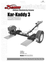
8605001 DRUM BRAKE
8605101 DISC BRAKE
ACTUATOR PARTS
REF
NO. PART NO. QTY DESCRIPTION
1. 12190-95 1 6000# 2” Lever Lock Coupler
2. SB23278 2 Roller
3. 12151 2 Front Roller Spacer
4. 02166 13/8”-16UNCX2-3/4”HexHeadBolt(gr.5)
5. 07176 13/8”-16UNCStoverLockNut
6. 05684 21/2”-13UNCx4-7/16”HexHeadBolt(gr.5)
7. 02178 21/2”-13UNCNylonInsertLockNut
8. 12193 1 Push Rod Assembly
9. 05692 1 Dampener/ Shock
10. 12103 2 Rear Roller Spacer
11. *05951 1 Emergency Lever
12. 12187 1 Front Cover Composite Black
13. *12200 1 28” Cable
14. 05960 25/16”-18UNCx1/2”Self-TappingScrew
15. 05424 2 5/16” External Tooth Lock Washer
16. *05693-95 1 Emergency Lever Spring
17. 03876 1Master Cylinder Cap w/ Diaphragm & O-ring
18. **00618 41/4-20UNCx2.00”HexHeadBolt
19. **00057 4 1/4” Spring Lock Washer
Please order replacement parts by PART NO. & DESCRIPTION
24
12
1
2
3
27
10
6
6
8
23
26
26
21
17
19
18
18
14
15
16
11
13
7
9
7
20
22
4
Do not tighten these bolts. They are
factory torqued and must remain loose
enough to allow free coupler movement.
25
29
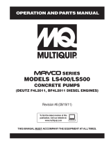
REF
NO. PART NO. QTY DESCRIPTION
20. 12191-95 1 Outer Case
21. **09153 1 Replacement Master Cyl. Gasket ONLY
22. **10616 1Master Cylinder (Not sold separately) Drum
-5650 - Master Cylinder Drum Kit (incl. items w/**)
-**11190 1Master Cylinder (Not sold separately) Disc
-5672 - Master Cylinder Disc Kit (incl. items w/**)
23. 05679 1.125FullOriceDrum
-11993 1Inline Blocking Solenoid Disc
24. **05687 1 Master Cylinder Protective Boot
25. BH21004 1 Safety Decal (See Page 6)
26. **00062 41/4-20UNCNut
27. 12557 1 Threaded Cap For Master Cylinder
28. 12267-95 1Solenoid Cover Disc
29. BD21001 2 Disc Brakes Decal (See Page 6)
30. 07283 110mm Flat Washer Disc
31. 02384 4 1/2” x 14GA NR Zinc Machine Washer
Please order replacement parts by PART NO. & DESCRIPTION
ACTUATOR PARTS LIST
Disc Brake
17
24
18
18
26
22
26
21
19
23
27
28
30
31

Page 9
5696
Coupler Repair Kit
for
6000 lb.
coupler
not included
REPAIR KIT PARTS LIST
5398 Master Cylinder Repair Kit for
Drum Brakes
(gasket 09153 included)
24
REF
NO. PART NO. QTY DESCRIPTION
-5398 - Master Cylinder Repair Kit w/gasket
-5400 - Emergency Lever Replace Kit ( incl. items w/*)
-5482 - Master Cylinder Repair Kit w/gasket
-5696 - Coupler Repair Kit (lever lock)
Please order replacement parts by PART NO. & DESCRIPTION
5482 Master Cylinder Repair Kit for
Disc Brakes
(gasket 09153 included)
24

Page 10
DEMCO MODEL DA66B BRAKE ACTUATOR
• Reviewallofthefollowinginstructionsbeforeinstallationanduseofhydraulicbrakeactuator.
• DealersorDistributorsmustreviewtheseinstructionswithultimateuser.
• Failuretofollowtheseinstructions,orfailuretoproperlymaintainbrakingsystemafterinstallation,can
result in loss of braking action which could cause severe property damage, personal injury or death.
To Prevent Serious Injury Or Death:
To avoid personal injury or death Do not weld on the outer case without disassem-
bling actuator. The excessive heat may cause the actuator not to function properly
To avoid personal injury or death, do not exceed lowest of (1) the rated capacity of
Model DA66B actuator, or (2) rated capacity of ball and hitch being used, or (3) trailer’s
Gross Vehicle Weight Rating (GVWR).
Model DA66B brake actuator has a maximum load rating of 6000 lbs. GVWR and 600
lbs. tongue load.
WARNING
WARNING
CAUTION
SPECIALNOTE–WHENPRESSUREBLEEDINGBRAKESITISSTILLNECESSARYTOSHORT
STROKETHEMASTERCYLINDERSEVERALTIMESTOELIMINATETRAPPEDAIRBUBBLES.
Elevate tongue on trailer 4-6 inches
Refer to actuator parts breakdown page to locate referenced part numbers associated with procedures below:
Visually inspect actuator to ensure the inner coupler (#1) is fully extended.
*Failure to perform this function will prevent proper and complete bleeding of system*
Loosen or remove two 5/16” bolts (#14) that hold the lever guide and flat emergency lever spring (#16). •
Removemastercylinderllcap(#17).
Usingshortstrokes,pullforwardonemergencylever(#11),pumpingmastercylinderuntilbrakeuidinmaster•
cylinder reservoir (#22) stops bubbling.
Attach a bleeder hose to a bleeder valve on one of the wheels (starting at wheel farthest from master cylinder) •
andsubmergeotherendintoatransparentcontainerpartiallylledwithbrakeuidtopreventpossiblesplash-
ing from container.
Loosen bleeder valve one turn and while watching fluid in container, use emergency lever (#11) to pump fluid •
as long as bubbles continue to leave submerged hose. When bubbles stop, close bleeder valve, move to next
wheelandrepeatuntilallbrakesarebled.(Note:Checkmastercylinderoften(every4-5strokes)andrell
above half full as needed )
Rellmastercylinderandsecurelyattachcap(#17).Reinstallemergencyleverspring,leverguide,lock•
washers and 5/16” hex head bolts. When tightening the bolts, make sure the lever moves freely in the groove
in the guide.
Test brakes by pulling emergency lever (#11) forward until it locks into position. Lever will be pointing approxi-
mately straight up. Attempt to rotate wheels in a forward direction. If any wheel rotates, brakes assemblies must
be adjusted.
Jackuptrailerandsecureonadequatecapacityjackstands.Followtrailermanufacturer’srecommendationsfor
lifting and supporting the unit. Make sure the wheel and drum rotates freely.
Remove the adjusting hole cover from the adjusting slot on the bottom of the brake backing plate.
With a screwdriver or standard adjusting tool, rotate the star wheel of the adjuster assembly to expand the brake
shoes.Adjustthebrakeshoesoutuntilthepressureoftheliningsagainstthedrummakesthewheelverydifcult
to turn in forward direction.
Back off the adjuster wheel 15-20 clicks. The wheel should turn freely with a possible, slight lining drag.
Replace the adjusting hole cover and lower the wheel to the ground. Repeat the above procedure on all brakes.
For best results, the brakes should all be set at the same clearance.
*Retest the brakes by locking the emergency lever on and attempt to rotate tires in a forward direction, if
any wheel turns there might be trapped air in the system yet.

Page 11
Actuator Trouble Shooting Guide
Symptoms Possible Solutions
Brakes Locking Up
Emergency lever partially pulled Release emergency lever.
(Lever must be in green zone).
(Emergency cable must have slack)
Debrisinmastercylinderorice Clean/ushorreplaceorice
Debris/rust in master cylinder Clean/flush or replace master cylinder
Pinched brake line or hose Replace brake line or hose.
Brake cluster hanging up Inspect wheel cylinder for rust and proper function
Check for broken springs
Check shoe adjustment (too tight)
Cluster mounting bracket bent
Trailer must be level or parallel with ground
Master Cylinder Not Priming
Master cylinder lever will not pump fluid Slide tube must be completely extended
Check fluid level.
Mastercylinderoriceplugged Clean/ushorreplacemastercylinder
Brakeuiddoesnotcomeoutoforice Clean/ushorreplaceorice
Brake fluid does not come out of brake line Inspect line/hoses for blockages.
Air in brake lines Check all line connections for air leaks
Check fluid level and bleed brakes
Leaking Master Cylinder
Brake fluid leaking out of push rod area Repair or replace master cylinder.
Brake fluid leaks out of gasket area Damaged gasket. Replace gasket.
Tighten master cylinder bolts in an alternating sequence
(10 inch lbs. torque)
Brake fluid leaks out of gasket area Master cylinder tightened unevenly.
Replace gasket and tighten bolts alternating sequence.
Donotoverllmastercylinder
Brakeuidleaksaroundorice Whenattachingmainbrakelinetoorice,useline
wrench and back-up wrench to prevent over-tightening
or damage to threads in master cylinder.
Brake Testing
Jack trailer wheels up off ground.
Spin wheel/wheels. Wheels should spin freely.
Pull emergency lever on as far forward as possible,
wheels should not turn by hand. Release emergency lever.
Wheels should spin forward without resistance.
SERVICING THE EMERGENCY LEVER
If emergency lever (#11) of actuator is applied, it can be disengaged by using a screwdriver to lift upward on front of flat
emergency lever spring (#16) while pulling lever forward until released. A thorough inspection of emergency lever,
emergency lever spring, and safety cable is required. Damaged parts must be replaced as follows:
A. Remove Cable (#13) from emergency lever (#11) and flat emergency lever spring (#16), then pull lever out of actuator
outer case (#20) through cross-slot in top.
B. Install new emergency lever through cross-slot in top of outer case. Attach new emergency lever spring.
C. Bolt emergency cable to emergency lever using bolt & locknut, leave loose to allow fork to pivot on lever.
D. Add adequate brake fluid to master cylinder and bleed brake system per instructions 4-6 in installation section.

Page 12
P.O. BOX 189
4010 320th St., BOYDEN, IA. 51234
PH: (712) 725-2311
FAX: (712) 725-2380
TOLL FREE: 1-800-54DEMCO (1-800-543-3626)
www.demco-products.com
Go online to www.demco-products.com for Demco
warranty policies & product registration.
/