Demco 91 User manual

Category
Motor vehicle electronics
Type
User manual

This manual is also suitable for

Page 1
DOING OUR BEST TO PROVIDE YOU THE BEST
ASSEMBLY
CALIBRATION
OPERATION
REPLACEMENT PARTS
READ complete manual CAREFULLY
BEFORE attempting operation.
1-04
BH20023, Rev 1
DEMCO Dethmers Mfg. Co. 4010 320th St. P.O. Box 189 Boyden, IA 51234
PH: (712) 725-2311 Toll Free: 1-800-543-3626 FAX: 1-800-845-6420
www.demco-products.com
OWNER/OPERATOR MANUAL
BRAKE ACTUATORS
MODEL 91
Page 2
Model DA91 is a heavy duty surge brake actuator for trailers with two or four wheels.
When brakes are applied on the towing vehicle, forward inertia of trailer toward towing
vehicle applies brakes on trailer in direct relation to manner brakes are applied on
towing vehicle. Brake towing vehicle hard and brakes on trailer are applied hard.
Master cylinder push rod spring assembly protects system from hydraulic pressure
overload.
DEMCO MODEL DA91 ACTUATOR
Review following instructions before installation and use of hydraulic brake
actuator.
Dealers or distributors must review these instructions with ultimate user.
Failure to follow these instructions, or failure to properly maintain braking
system after installation, can result in loss of braking action.
WARNING: To Prevent Serious Injury or Death
Table of Contents
General Information ............................................................................................................2
Safety Sign Locations.........................................................................................................3
Bolt Torque ..........................................................................................................................4
Bolt/Weight Rating Warning .................................................................................................5
Actuator Installation and Maintenance .............................................................................. 6-7
Demco Brake Products Limited Warranty ............................................................................8
Demco Brake Products Limited Warranty Cont....................................................................9
Actuator Parts Breakdown and Parts List...........................................................................10
Hitch Configurations...........................................................................................................11
Page 3
BRAKES ON
DO NOT TOW
BRAKES OFF
TOWABLE
BH21003
SAFETY SIGN LOCATIONS
Types of safety sign and locations on equipment are shown in illustration below. Good safety
requires that you familiarize yourself with various safety signs, type of warning, and area or
particular function related to that area, that requires your SAFETY AWARENESS.
Replacement Part #BH21003 Qty. 1
This decal is positioned as shown
Page 4
Tighten all bolts to torques specified in chart unless otherwise noted. Check tightness of bolts
periodically, using bolt chart as guide. Replace hardware with same grade bolt.
NOTE: Unless otherwise specified, high-strength Grade 5 hex bolts are used throughout assembly
of equipment.
Bolt Torque for Standard bolts *
GRADE 2 GRADE 5 GRADE 8
A lb-ft (N.m) lb-ft (N.m) lb-ft (N.m)
1/4 6 (8) 9 (12) 12 (16)
5/16 10 (13) 18 (25) 25 (35)
3/8 20 (27) 30 (40) 45 (60)
7/16 30 (40) 50 (70) 80 (110)
1/2 45 (60) 75 (100) 115 (155)
9/16 70 (95) 115 (155) 165 (220)
5/8 95 (130) 150 (200) 225 (300)
3/4 165 (225) 290 (390) 400 (540)
7/8 170 (230) 420 (570) 650 (880)
1 225 (300) 630 (850) 970 (1310)
Torque figures indicated are valid for
non-greased or non-oiled threads and
heads unless otherwise specified.
Therefore, do not grease or oil bolts or
capscrews unless otherwise specified
in this manual. When using locking
elements, increase torque values
by 5%.
* GRADE or CLASS value for bolts
and capscrews are identified by their
head markings.
Torque Specifications
CLASS 8.8 CLASS 9.8 CLASS 10.9
A lb-ft (N.m) lb-ft (N.m) lb-ft (N.m)
6 9 (13) 10 (14) 13 (17)
7 15 (21) 18 (24) 21 (29)
8 23 (31) 25 (34) 31 (42)
10 45 (61) 50 (68) 61 (83)
12 78 (106) 88 (118) 106 (144)
14 125 (169) 140 (189) 170 (230)
16 194 (263) 216 (293) 263 (357)
18 268 (363) -- -- 364 (493)
20 378 (513) -- -- 515 (689)
22 516 (699) -- -- 702 (952)
24 654 (886) -- -- 890 (1206)
Bolt Torque for Metric bolts *
GRADE-2 GRADE-5 GRADE-8
8.8
10.9
9.8
CLASS 8.8 CLASS 9.8 CLASS 10.9
Page 5
WELDING
The weight rating of the coupler is dependent on
the correct bolts being used. You must use the
bolts provided with the product. If you are miss-
ing bolts, refer to your Operatorís Manual and ob-
tain replacements from Demco, or use the exact
size, grade, and number of bolts as specified. Us-
ing the wrong size, grade, or number of bolts will
reduce the weight rating of the coupler and could
cause separation of your towing equipment from
the towing vehicle. If you have questions about
the correct bolts for your application call Demco
at any of the following telephone numbers:
(712) 725-2311
(712) 725-2302
1-800-543-3626
FAX: 1-800-845-6420
WARNING: TO AVOID PERSONAL INJURY OR PROPERTY
DAMAGE, OBSERVE THE FOLLOWING INSTRUCTIONS:
!
Tack Actuator down on the
four corners then weld in a
criss cross pattern using 2î
to 2-1/2î welds with 2î
spaces between welds
(when welding down to a
flat area of the tongue)
Do not weld in the
circled area
Do not weld in the
circled area
Keep braces and welds
back to allow access to
shock pin holes
Keep braces
and welds
back to allow
access to
shock pin hole
Use gussets to sup-
port the back of the
actuator if welding in
position shown
Keep gussets
on rear of ac-
tuator to lower
half to avoid
circled area
Weld as shown
NOTE: disassembly of the actuator before welding is recommended
Page 6
DEMCO MODEL DA91 BRAKE ACTUATOR
INSTALLATION
(SEE PAGE 10 FOR BREAKDOWN AND REFERENCE NUMBERS)
Model DA91 is completely assembled and ready to bolt or weld into place.
1. Standard DA91 actuators come with a variety of mounting channels. (see Page 11)
2. Connect and tighten all brake lines.
3. Fill master cylinder (#21) with DOT 3 or 4 brake fluid.
4. Bleed brake system using a pressure-type brake bleeder or manually, as follows:
a. Remove two 5/16" hex head bolts (#13) and lock washers (#8) that hold lever guide
(#23) and flat emergency lever spring (#12). Remove lever guide and emergency lever spring.
Using short strokes, pull forward on emergency lever (#16), pumping master cylinder until
brake fluid within master cylinder stops bubbling.
b. Attach a bleeder hose to bleeder valve on one of the wheels and submerge other end of hose
into a transparent container partially filled with brake fluid. Loosen bleeder valve one turn
and, watching hose in transparent container, use emergency leverto pump master cylinder
as long as air bubbles continue to leave the hose. When bubbles stop, close bleeder valve,
move to next wheel, and repeat process until all brakes have been bled. (Note: Check fluid level
in master cylinder frequently while bleeding brakes (every 4 or 5 strokes). Refill as necessary
to keep level above half full.)
Review all of the following instructions before installation and use of hydraulic brake
actuator.
Dealers or Distributors must review these instructions with ultimate user.
Failure to follow these instructions, or failure to properly maintain braking system after
installation, can result in loss of braking action which could cause severe property damage,
personal injury or death.
To Prevent Serious Injury Or Death:
Model DA91 brake actuator has a maximum load rating of 8,000 lbs.
GVWR and 750 lbs. tongue load.
To avoid personal injury or death, do not exceed lowest of (1) the rated
capacity of Model DA91 actuator, or (2) rated capacity of ball, hitch, and
coupler being used, or (3) trailer's Gross Vehicle Weight Rating (GVWR).
Model DA91 brake actuator has a maximum tongue load equal to 10% of
the maximum load rating.
WARNING
WARNING
Page 7
MAINTENANCE
1. Frequently check brake fluid level. (Fluid must be approved, clean, and uncontaminated.)
2. Make sure actuator mounting bolts are secure.
3. Inspect actuator, replace bent, worn, or damaged parts.
4. Be constantly aware of systems braking quality, make periodic checks as described in brakes ownerís
manual. Consult certified brake specialist to make necessary adjustments or repairs. Failure to do so
could result in loss of braking.
SERVICING THE EMERGENCY LEVER
(SEE PAGE 10 FOR BREAKDOWN AND REFERENCE NUMBERS)
If emergency lever (#16) of actuator is applied, it can be disengaged by using a screwdriver to lift
upward on front of flat emergency lever spring (#12) while pulling lever forward until released.
A thorough inspection of emergency lever, emergency lever spring, and cable with S-hooks is required.
Damaged parts must be replaced as follows:
a. Remove master cylinder (#21) and push rod assembly (#18). Be careful not to get dirt into
master cylinder. (A new Master Cylinder Gasket (#20) should be used when reinstalling.)
b. Remove Cable S-hook (#10) from emergency lever (#16), emergency lever guide (#23) and flat
emergency lever spring (#12), then pull lever out of actuator outer case (#7) through cross-slot
intop.
c. Install new emergency lever through cross-slot in top of outer case. Attach new emergency lever
spring and emergency lever guide.
d. Insert S-hook on emergency cable (#10) into hole in emergency lever(#16) and squeeze shut.
e. Add adequate brake fluid to master cylinder and bleed brake system per instructions 4-6 in installation
section.
5. Once bleeding is completed, refill master cylinder and attach cap (#17) securely. Replace
emergency lever spring, lever guide, lock washers and 5/16" hex head bolts.
6. Test brakes by pulling emergency lever (#16) forward until it locks into its second notch
position. (Lever should be approximately straight up.) Attempt to rotate wheels in a forward
direction. If any wheels rotate, brakes must be adjusted. To adjust brakes, release
emergency lever from locked position, set each wheelís brake adjustment up 2 or 3 notches
(per instructions in appropriate brake cluster manual). Repeat test procedure as necessary.
Page 8
1. Extent and Duration of this Warranty:
Your Demco brake product is warranted to be free from defects in materials and workmanship under normal use
and service for a period of one year after date of purchase by original owner when properly installed, used and
maintained by purchaser.
When this Demco brake product is used as part of complete Demco braking system (actuators, brake lines, and
back plates), Demco warrants system to be free from defects in materials and workmanship for two years when
properly installed, used, and maintained by purchaser.
Any part of Demco brake system found to be defective in materials or workmanship will be repaired or replaced at
manufacturers option without charge for parts or labor to original owner.
2. Manufacturer and Warrantor of Trailer:
Dethmers Manufacturing Co.
4010 320th Street
P.O. Box 189
Boyden, IA 51234
(712) 725-2311
3. Repair or Replacement Procedure:
If your Demco brake product develops a defect during warranty period, promptly notify Dethmers Manufacturing
Co. customer service department. Until such notice is received, warrantor will not be responsible for any repair or
replacement.
Upon receipt of timely notice from you, warrantor will have a choice of options in replacing any part it determines
to be defective:
a) Warrantor may require you at your own expense to deliver or ship part to its factory or authorized
dealer. Any defective part will be repaired or replaced and returned to you or your authorized dealer
free of charge. Any part returned to warrantor and found not to be defective will be returned to you
freight collect with explanation.
b) Warrantor may ship a new part to dealer to be exchanged free of charge for defective
part returned by you.
c) Warrantor may ship or deliver a replacement part to you at your address.
4. Limitations on Warranty Coverage:
Coverage under this warranty will be effective only when a copy of original invoice, showing date and location of
purchase, accompanies any claim for warranty.
Warrantor has no liability whatsoever and this warranty is null and void if any Demco brake product has been
misassembled or subjected to damage or neglect, negligence, misuse, accident or operated in any way contrary
to operating and maintenance instructions as specified in Demco owners manual for that product.
This warranty does not cover any product that has been altered or modified so as to affect the productís
operation, performance or durability, or that has been modified to change intended use of product.
In addition, warranty does not extend to repairs made necessary by abnormal use, damage, unreasonable
use including failure to provide reasonable and necessary maintenance, or by use of parts, accessories or
other equipment which are incompatible with Demco brake products or affect its operation, performance
or durability.
DEMCO BRAKE PRODUCTS - LIMITED WARRANTY
Page 9
DEMCO BRAKE PRODUCTS - LIMITED WARRANTY CONTINUED
DISCLAIMER
This warranty does not cover:
a) normal wear and tear.
b) road film or gravel damage to paint.
c) paint.
d) rust damage.
e) any Demco brake product that has been loaded in excess of load capacity stated on identifica-
tion label.
f) Accessory parts, materials or components.
Warrantor has a policy of continuous product improvement. We reserve the right to change or
improve design of any Demco brake product, including but not limited to state of the art changes,
without assuming any obligation to modify any product previously manufactured.
Warrantor assumes no responsibility to owner for loss of use of product, loss of time, inconve-
nience or other damage consequential or otherwise, including, but not limited to expense forgaso-
line, expense of transporting product to dealer and expense of returning product, mechanics travel
time, telephone, telegram, fax, overnight delivery, or postage charges, road service/towing
charges, rental during time warranty repairs are being performed, travel, lodging, loss or damage
to personal property or loss of revenue or earnings.
5. Limitations of Implied Warranties:
All implied warranties, if any, expire and terminate upon expiration of this warranty. Some states
do not allow limitation on how long an implied warranty lasts, so this limitation may not apply to
you.
6. Limitation of Consequential Damages:
Warrantorís responsibility under this warranty extends solely to repair or replacement of your
Demco brake product and its component parts. Warrantor does not assume responsibility for, nor
shall it be liable for, any special, incidental or consequential damages. Some states do not allow
exclusion or limitation of incidental or consequential damages, so above exclusion or limitation
may not apply to you.
7. Purchasers Rights:
This warranty gives you specific legal rights, and you may also have other rights which vary from
state to state.
8. Exclusive Warranty:
This is the only express warranty made by Dethmers Manufacturing Co. on your Demco product
and no agent, employee, or other person is allowed to change or add to this warranty.This war
ranty extends solely to repair or replacement of your Demco brake product and its component
parts. Warrantor does not assume any liability or responsibility not expressly covered by this
limited warranty.This warranty supersedes all prior warranties, written or implied.
No other express warranty has been made or will be made on behalf of warrantor with respect to
Demco brake product or its instruction, operation, repair or replacement.Warrantor shall not be
responsible for damage, loss or damage to personal property, whether direct or indirect, and
whether arising in contract or tort.
Page 10
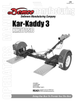
ACTUATOR PARTS BREAKDOWN
5221
Coupler Repair Kit
2î Ball Coupler RATED
AT 6000#
not included
29
REF.
NO. PART NO. QTY. DESCRIPTION
Model 91 ACTUATOR PARTS LIST
1. 05432 1 6000# 2" Ball Coupler (zinc plated)
2. 01896 3 1/2"-13UNC x 4" Hex Head Bolt (gr.5)
3. 02178 3 1/2"-13UNC Nylon Insert Lock Nut
4. 05441-95 1 Front Shock Pin 5/8" dia x 3 (straight tube)
- 05426 1 Front Shock Pin (drop tube actuators)
5. 11078-?? 1 Straight Tube Actuator Slider
- 11079-?? 1 Drop Tube Actuator Slider
6. SB12426 1 Damper/ Shock
7. 11164-?? 1 3 Bolt Mount Outer Case
8. 05424 2 5/16" External Tooth Lock Washer
9. 02363 2 5/32" x 1 1/4 Cotter Pin(Qty 3 w/drop tube)
**10. 05408 1 3/32" Cable with hooks
11. SB10555 - Replacement S-Hooks ONLY
**12. 05693-?? 1 Emergency Lever Spring
13. 05961 2 5/16"-18UNC x 5/8" Hex Head Bolt (gr.5)
14. 00618 4 1/4-20UNC x 2" Hex Head Bolt (gr.5)
15. 00057 4 1/4" Lock Washer
**16. 05951-?? 1 Emergency Lever Assembly
17. 03876 1 Master Cylinder Cap w/ Diaphragm & O-ring
- 05849 1 O-Ring Only (not shown)
18. 05977 1 Push Rod Assembly
19. 00062 4 1/4-20 UNC Hex Nut
20. 09153 - Plastic Master Cyl. Gasket ONLY
21. 10616 1 Master Cylinder (drum brakes)
- 11190 - Master Cylinder (discbrakes)
22. SB12098 1 .018 Connector Orifice (Drum Brakes)
- 05679 1 Inverted Flare Adapter (Disc Brakes)
23. 03866-?? 1 Lever Guide
24. 05687 1 Master Cylinder Protective Boot
25. 05986-?? 1 Connecting Pin
26. 10965 1 Upper Slider
27. 10966 1 Lower Slider
28. 10967 2 Side Spacers
- 5401 - Lever Replacement Kit (incl. items w/**)
- 5650 - Master Cyl. Replacement Kit (drum)
- 5672 - Master Cyl Replacement Kit (disc)
- 5221 - Coupler Repair Kit
29. 02920 - Thumb Lock ONLY
5398 Master Cylinder
Repair Kit (drum)
(gasket 09153 included)
23
**16
22
20
21
19
17
24
13
14
11
9
**10
6
4
3
2
7
5
15
1
8
REF. PART
NO. NO. QTY. DESCRIPTION
KIT #5404 PARTS LIST
30. 04594 - EPDM Black Tubing
31. 05561 1 Solenoid Valve
32. 09153 1 Master Cylinder Gasket (not shown)
33. 10373 1 Brass Fitting Str. .2 HB x 10-32 NF
34. 10374 2 Crimp Clamp
35. 10375 1 Straight Nipple 1/8 MPT x 1/8 MPT
36. 10376 1 Brass Elbow 1/8 MPT x .2 HB
Drill the hole using a 5/32î bit. Hole location
is .900î right of top left corner and .900î down
from top of master cylinder. Tap hole with 10-32 NF tap
30
31
33
34
35
36
34
Please order replacement parts by PART NO. and DESCRIPTION
Remove Fitting (#22)
from Master Cylinder
and relocate to this hole
2
8
9
14
15
18
19
25
26
27
28
28
**12
5482 Master Cylinder
Repair Kit (disc)
(gasket 09153 included)
5
Optional Drop Tube
Slider
See Page 19 for additional Slider
Tube and Outer Case options
4
9
Note: -?? = -30 Black -91 Yellow Chromate
-95 Plated -97 Primed Red
Indicate color when ordering parts
(OPTIONAL) FREE BACKING
SOLENOID KIT PARTS BREAK-
DOWN 5404 (FIELD INSTALL)
5629 (FACTORY INSTALL)
Page 11
45
43
43
51
44
47
46
54
53
52
44
48
56
56
54
54
54
55
REF.
NO. PART NO. QTY. DESCRIPTION
PARTS LIST
37. 11101-?? 1 Outer Case w/ no mounts
38. 11171-?? 1 Outer Case w/ plate
39. 11163-?? 1 Outer Case w/ 50 mount
40. 11168-?? 1 Outer Case w/ 3 hole mount
41. 11170-?? 1 Outer Case w/ universal holes
42. 11169-?? 1 Outer Case w/ 2 hole mount
43. 02587 2 5/8"-11UNC Nylon Insert Lock Nut
44. 02434 2 5/8"-11UNC x 4 1/2" Hex Head Bolt (Gr. 5)
45. 11076-?? 1 Channel Down Slider
46. 11077-?? 1 Channel Up Slider
47. 09557-?? 1 Pintle Ring (10 Ton Capacity)
48. 05593-?? 1 Clevis
49. 07678-?? 1 2-5/16" Lever Lock Bolt-On Coupler
50. 09430-?? 1 2î Lever Lock Coupler
51. 11070-?? 1 2-5/16" Bulldog Coupler Welded to Straight Slider Tube
- 11071-?? 1 2" Bulldog Coupler Welded to Straight Slider Tube
52. 11069-?? 1 2-5/16" Bulldog Coupler Welded to Drop Slider Tube
- 11072-?? 1 2" Bulldog Coupler Welded to Drop Slider Tube
53. 05557-?? 1 2-5/16" Bulldog Coupler Welded to Clevis Channel
- 05823-?? 1 2" Bulldog Coupler Welded to Clevis Channel
54. 04051 4 5/8"-11UNC x 1-1/2" Hex Head Bolt (Gr.5)
55. 11075-?? 1 Channel Centered Slider
56. 03730 4 5/8" Stover Locknut
57. 11081-?? 1 Slider w/ Flat Plate Mount
58. 11073-?? 1 Straight Slider w/ 2î Coupler
59. 11074-?? 1 Drop Tube Slider w/ 2-5/16î Coupler
49
54
56
58
59
50
54
56
56
57
OUTER CASE OPTIONS AND AVAILABLE HITCH CONFIGURATIONS
37 38 39
40 41 42
2 RATED AT 7000#
Please order replacement parts by PART NO. and
DESCRIPTION and COLOR.
Note: -?? = -30 Black -91 Yellow Chromate
-95 Plated -97 Primed Red
The weight rating of the coupler is dependent on the
correct bolts being used. You must use the bolts
provided with the product. If you are missing bolts,
refer to your Operatorís Manual and obtain replace-
ments from Demco, or use the exact size, grade,
and number of bolts as specified. Using the wrong
size, grade, or number of bolts will reduce the weight
rating of the coupler and could cause separation of
your towing equipment from the towing vehicle. If
you have questions about the correct bolts for your
application call Demco at any of the following tele-
phone numbers:
(712) 725-2311
(712) 725-2302
1-800-543-3626
FAX: 1-800-845-6420
WARNING: TO AVOID PERSONAL INJURY OR
PROPERTY DAMAGE, OBSERVE THE FOLLOWING
INSTRUCTIONS:
!
2 -5/16 RATED AT 8000#
2 -5/16 RATED AT 8000# 2 -5/16 RATED AT 8000#
2 RATED AT 7000#
2 -5/16 RATED AT 8000#
RATED AT 8000#RATED AT 8000#
RATED AT 6000#
54
54
Page 12
DETHMERS MFG. COMPANY
P.O. BOX 189
4010 320th St., BOYDEN, IA. 51234
PH: (712) 725-2311 FAX: (712) 725-2380
TOLL FREE: 1-800-54DEMCO (1-800-543-3626)
www.demco-products.com
  • Page 1 1
  • Page 2 2
  • Page 3 3
  • Page 4 4
  • Page 5 5
  • Page 6 6
  • Page 7 7
  • Page 8 8
  • Page 9 9
  • Page 10 10
  • Page 11 11
  • Page 12 12

Demco 91 User manual

Category
Motor vehicle electronics
Type
User manual
This manual is also suitable for

Ask a question and I''ll find the answer in the document

Finding information in a document is now easier with AI