Page is loading ...

Installation notes
DANLERS Limited, Vincients Road, CHIPPENHAM, Wiltshire, SN14 6NQ, UK.
Telephone: +44 (0)1249 443377 Fax: +44 (0)1249 443388
E-mail: [email protected] Web: www.danlers.co.uk
Company Registered Number 2570169 VAT Registration Number 543 5491 38
Products available from DANLERS
• PIRoccupancyswitches•Daylightlinkeddimmers•Manualhighfrequencydimmers
• Photocells • Radio remote controls • Time lag switches • Outdoor security switches
• Dimmers•Heating,ventilationandair-conditioningcontrols•Bespoke/O.E.M.products
Please call for more information or a free catalogue, or visit our website.
ThisproductconformstoBSEN60669-2-1andBSEN55015.
Pleaseensurethemostrecenteditionoftheappropriatelocalwiringregulationsareobserved
andsuitableprotectionisprovidede.g.a10ampcircuitbreakerandvoltagesurgeprotection.
Pleaseensurethatthisdeviceisdisconnectedfromthesupplyifaninsulationtestismade.
Thisproductiscoveredbyawarrantywhichextendsto5yearsfromthedateofmanufacture.
Precautions and Warranty
Wall mounted override switch
WAOSW
DANLERSWAOSWswitchissuitableforwallmountingforoverride
controlofDANLERSPIROccupancyswitches(3wireversions
only),orDANLERSControlZAPPdevices.WAOSWmayalsobe
suitableforusewithotherthirdpartyPIRoccupancyswitches.
WAOSWrequiresminimumwallboxdepthof35mm.
Switch options
ROCKER SWITCH
Therockerswitchusedtochoosebetween
leavingthelights(orotherload)inAUTOMATIC
mode (controlled by the DANLERS control), or
overriddenOFF.
PUSH BUTTON
TheilluminatedpushbuttonisforTemporary
timedoverride.Atanytimethepushbutton
canbeusedtooverridethelights(orother
load)ONtemporarily,forthetimelagsetting
asdeterminedbyspindleonthebackofthe
product. The time lag settings are adjustable
from1minuteto120minutes.Thetemporary
overrideONcanbecancelledbyafurtherpress
on the push button.
DANLERSWAOSWcanswitchupto:
• 6amps(1500W)ofresistiveloads.
• 6amps(1500W)ofuorescentloads.
• 6amps(750W)ofelectronictransformerloads.
• 3amps(750W)wirewoundtransformerloads.
• 2amps(500W)ofCFL,2Dlamps,LEDDriversandLEDlampsandttings.
• 1amp(250W)offans.
Minimumload:2Wofresistive.
26/11/15 INS235WAOSW
Loading
Time lag switch “clicks” off but load stays on:
• Non-resistiveload(contactor,emergency,CFL,LEDor2Dlamp)
AddCAPLOAD/RESLOADEacrosstheloadasshownin
wiringdiagram.
• Faultdevelopedduetoanover-voltagespike.
Load latched either on or off:
• Faultdevelopedduetoonover-voltagespike.
Troubleshooting
PUSH BUTTON:
Timed override OFF
when illuminated.
Timed override ON
when not illuminated.
ROCKER SWITCH:
A
utomatic mode ON
press down or
A
utomatic mode OFF
press up

Installation procedure
1.Pleasereadthesenotescarefullybeforecommencingwork.
Incaseofdoubtpleaseconsultaqualiedelectrician.
2.Makesurethepowerisisolatedfromthecircuit.
TheWAOSWshouldbeconnectedasshownindiagramsA&B:
THISSECTIONTOBECOMPLETEDBYENGINEERING
3.WAOSWswitchesshouldbeconnectedas:
L Live
SL SwitchedLineoutput
S Slaveconnection
4 Whenthesedevicesarewiredinparallel,dependantontheload,it
may not be possible to immediately re-trigger the time lag.
5.Thetimelagisadjustedviaaspindlelocatedonthebottomedgeof
thedevice,aseediagramC.
6.Whenwiringhasbeencompletedandveried,switchonsupplyand
test operation.
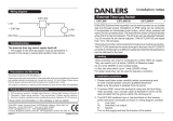
A. Typical wiring diagram
Load
L
N
230 VAC
SL
Time lag switch
N
Rocker switch
DANLERS PIR
or ControlZAPP
Device
WAOSW
B. Wiring connections
Drawing of back of
product showing
wiring connections
Engoneering to instruct
C. Time lag settings
TIME
1120
2
5
10 17.5 40
60
90
APPROXIMATE
SETTINGS
(In minutes)
/
