Page is loading ...


2
Before reading this manual
This operation manual contains basic instructions on installing and using DirectIP™ Network Video Recorder, an
IDIS product.
Users who are using this product for the first time, as well as users with experience using comparable products,
must read this operation manual carefully before use and heed to the warnings and precautions contained herein
while using the product. Safety warnings and precautions contained in this operation manual are intended to
promote proper use of the product and thereby prevent accidents and property damage and must be followed at
all times.
Once you have read this operation manual, keep it at an easily accessible location for future reference.
•The manufacturer will not be held responsible for any product damage resulting from the use of unauthorized parts
and accessories or from the user's failure to comply with the instructions contained in this operation manual.
•It is recommended that first-time users of DirectIP™ Network Video Recorder and individuals who are not familiar with
its use seek technical assistance from their retailer regarding product installation and use.
•If you need to disassemble the product for functionality expansion or repair purposes, you must contact your retailer
and seek professional assistance.
•Both retailers and users should be aware that this product has been certified as being electromagnetically compatible
for commercial use. If you have sold or purchased this product unintentionally, please replace with a consumer
version.
Safety Symbols
Symbol Type Description
Warning An important instruction or set of important instructions that can lead to severe injury or
even death if not followed.
Caution An instruction or set of instruction that can lead to personal injury and/or property
damage if not followed.
In-Text
Symbol Type Description
Caution Important information concerning a specific function.
Note Useful information concerning a specific function.

Before reading this manual
3
FCC Compliance Statement
Note: This equipment has been tested and found to comply with the limits for a Class A digital device, pursuant to
part 15 of the FCC Rules. These limits are designed to provide reasonable protection against harmful interference
when the equipment is operated in a commercial environment.
This equipment generates, uses and can radiate radio frequency energy and, if not installed and used in
accordance with the instructions, may cause harmful interference to radio communications. Operation of this
equipment in a residential area is likely to cause harmful interference in which case the user will be required to
correct the interference at his own expense.
User’s Caution Statement
Caution: Any changes or modifications to the equipment not expressly approved by the party responsible for
compliance could void your authority to operate the equipment.
Copyright
© 2013 IDIS Co., Ltd.
IDIS Co., Ltd. reserves all rights concerning this operation manual.
Use or duplication of this operation manual in part or whole without the prior consent of IDIS Co., Ltd. is strictly
prohibited.
Contents of this operation manual are subject to change without prior notice.
Registered Trademarks
IDIS is a registered trademark of IDIS Co., Ltd.
Other company and product names are registered trademarks of their respective owners.
This product contains open source software. Codes for the corresponding open-source content are available
for download. For more information, refer to the software CD (OpenSourceGuide\OpenSourceGuide.pdf) or the
open source guide accompanying this operation manual.

4
Safety Precautions
Information contained in this section of the manual serves to prevent accidents and property damage through
proper use of the product. Please read the following instructions carefully and follow them at all times.
Warning Failure to comply can lead to severe injury or even death.
Installation
Make sure to turn off the
product before installing it
and to use a dedicated power
outlet.
Presents overheating, fire, and
electric shock hazards.
There are high-voltage
components inside the
product. Do not attempt
to open the cover or
disassemble, repair, or
modify the product.
Presents fire, electric shock, and
physical injury hazards.
Use the product in
conjunction with protective
equipment that minimizes
damage from power outages
and lightning strikes.
Presents fire, electric shock, and
physical injury hazards.
Make sure to turn off the
product before expanding the
system (such as installation
of additional cameras). Do
not under any circumstance
connect a signal line while
the product is in operation.
Presents fire, electric shock, and
physical injury hazards.
Connection ports on the rear
of the product protrude out
slightly, and placing the back
of the product too close to a
wall will cause the cables to
bend excessively and even
break. Maintain a distance
of at least 15cm between the
back of the product and the
wall it faces.
Presents fire, electric shock, and
physical injury hazards.
Do not use the product in
an excessively hot (40˚C or
above), cold (5°C or below),
or humid environment.
Presents a fire hazard.

Safety Precautions
5
Do not use the product in an
particularly humid, dusty, or
sooty environment.
Presents electric shock and fire
hazards.
Set up the product in a
shaded area providing
protection against exposure
to direct sunlight and
maintain an even ambient
temperature. Do not set up
the product in the vicinity of
heat-generating objects and
appliances such as candles
and heaters.
Presents a fire hazard.
Thinner
Always keep the operating
environment clean and free
of dust. Use a piece of dry
cloth to clean the product.
Do not use water, thinner, or
organic solvents.
Failure to do so can damage the
product's finish and presents
malfunction or electric shock
hazard.
Power
Voltage fluctuation of the
power supply must be within
10% of the voltage rating,
and the power outlet must
be grounded. Do not plug in
electrical appliances such
as a hair dryer, iron, and
refrigerator into the same
power outlet as the product.
Presents overheating, fire, and
electric shock hazards.
Do not bend the power cable
excessively or place heavy
objects on top of it.
Presents a fire hazard.
Do not pull on the power
cable or handle the power
plug with wet hands. Do not
insert the power plug into a
loose power outlet.
Presents fire and electric shock
hazards.

Safety Precautions
6
Product Use
If a liquid or debris has
entered inside the product,
unplug the power cable and
contact the service center
right away.
Presents malfunction and fire
hazards.
If there is a strange noise
or smell coming from the
product, unplug the power
cable and contact the service
center right away.
Presents fire and electric shock
hazards.
Risk of explosion if battery is
replaced by an incorrect type.
Dispose of used batteries
according to the instructions
Avoid dangerous situations
such as placing the product
or its power cable on a
humid/wet floor, using an
ungrounded extension cord,
using a damaged (exposed)
power cable, and failing to
properly ground the product.
Contact the retailer or a
specialist if you encounter a
problem.
Presents fire and electric shock
hazards.
Caution Failure to comply can lead to minor injury and/or product damage.
Installation
Do not set up the product
in an area that is exposed
or susceptible to strong
magnetism, radio waves,
and/or impact and avoid
setting up the product
in the vicinity of wireless
transmission devices such as
a radio or a television.
Set up the product in an area
devoid of magnetic objects,
radio waves, and vibrations.
Set up the product on a flat
and stable surface. Do not
stand the product on its side
or at an angle.
The product may tip over or
drop on the floor, which can lead
to a malfunction and/or personal
injury.
Set up the product in an open
and well-ventilated area.
Environmental factors greatly
affect the product's performance
and durability. Allow at least
15cm of clearance behind the
product and at least 5cm of
clearance on either side of the
product.
Ensure the product's power
plug is easily accessible.
It must be easy to pull out the
power plug in the event of a
serious malfunction or fire.

Safety Precautions
7
Do not set up the product in
an area susceptible to strong
impact or vibrations.
Failure to do so can cause the
product to malfunction.
Product Use
Do not place heavy objects
on top of the product.
Failure to do so can cause the
product to malfunction.
Do not allow conductive
objects to enter inside
the product's ventilation
openings.
Failure to do so can cause the
product to malfunction.
Do not unplug the power
cable or pick up/move
the product while it is in
operation.
Failure to do so can cause the
product to malfunction.
A flashing Rec LED on the
front of the product indicates
data is being recorded on the
HDD.
Regularly check to see if the Rec
LED is flashing.
Changing the settings in
order to continue recording
data once the HDD reaches
its maximum capacity
will effectively overwrite
existing data with new data.
Check once more before
proceeding.
Once the HDD reaches
the end of its service life,
the data stored on it could
become irrecoverably
damaged. A damaged data
file (when played back)
indicates that the HDD may
have reached the end of
its service life. Contact the
retailer or service center and
arrange for a replacement
right away.
Regularly inspect the
operating status of the
product and contact the
retailer or service center
right away if any issues are
identified.

8
Table of Contents
1
2
Part 1 – Introduction ................................11
Product Features ..............................................11
Accessories ..................................................12
Overview ....................................................13
Front Panel ...........................................................13
Rear Panel ...........................................................17
Rear Panel Connections .................................................18
Connections on the Rear Panel ...........................................21
Remote Control .......................................................22
Part 2 - Getting Started ..............................25
Setup Wizard .................................................25
Camera Registration ............................................26
Camera Scan Button ...................................................26
Camera View Buttons ...................................................27
Camera List Area ......................................................28
Video Display Area .....................................................28
Apply/Cancel Buttons ...................................................29
Camera Registration Mode .......................................29
Login .......................................................30
Live Mode ....................................................31
Live Menu ...........................................................31
Zoom ...............................................................32
PTZ Control ..........................................................33
Event Monitoring ......................................................34
Covert Camera ........................................................34
Context Menu Access ..................................................35
Edit Group ...........................................................35
Video Recording ...............................................35
Panic Recording .......................................................35
Audio Recording ...............................................36
Video Recording Playback .......................................36
All Channel Playback ...................................................36

Table of Contents
9
Remote Control Buttons during Playback . . . . . . . . . . . . . . . . . . . . . . . . . . . . . . . . . . . . 36
Context Menu ........................................................36
Part 3 - Configuration ...............................37
Menu Use ....................................................37
Text Input via Virtual Keyboard ............................................37
Batch Assignment .....................................................37
Mouse ..............................................................38
System Setup .................................................38
General .............................................................38
Date/Time ...........................................................39
User ................................................................40
Storage .............................................................42
Monitoring ...........................................................42
Camera Setup ................................................44
General .............................................................44
Advanced Setup .......................................................44
Stream ..............................................................47
Audio ...............................................................47
Upgrade .............................................................48
Record Setup .................................................48
General .............................................................48
Schedule ............................................................49
Pre-Event ............................................................51
Event Setup ..................................................51
Video-Analytics. . . . . . . . . . . . . . . . . . . . . . . . . . . . . . . . . . . . . . . . . . . . . . . . . . . . . . . . 51
Alarm-In .............................................................54
Video Loss ...........................................................55
Audio Detection .......................................................55
Text-In ..............................................................56
Device Setup .................................................57
Alarm-Out ...........................................................57
Network Setup ................................................57
General .............................................................57
IP Address ...........................................................58
FEN ................................................................59
3

Table of Contents
10
Notification Setup ..............................................59
Schedule ............................................................59
Callback ...........................................................59
Mail ................................................................60
SNS ................................................................61
Push ...............................................................61
Display Setup .................................................61
OSD ................................................................61
Main Monitor .........................................................62
Status Setup. . . . . . . . . . . . . . . . . . . . . . . . . . . . . . . . . . . . . . . . . . . . . . . . . . 62
Event ...............................................................62
Storage .............................................................63
Part 4 - Search .....................................64
Time-Lapse Search ............................................64
Search Menu .........................................................65
Context Menu ........................................................68
Motion Search ........................................................68
Text-In Search ........................................................69
Clip Copy ............................................................69
Print ................................................................70
Event Log Search ..............................................71
Overlapped Recording Search ....................................72
Part 5 - IDIS Web ...................................73
Web Live Mode ...............................................74
Web Search Mode .............................................76
Part 6 - Appendix ...................................79
System Log Types .............................................79
Error Code Types ..............................................80
Troubleshooting ...............................................82
Specifications .................................................83
Index .......................................................85
4
5
6

11
Product Features
This is a DirectIP™-enabled video recorder that supports surveillance, video recording, and video playback using a
network of cameras.
This NVR (Network Video Recorder) unit offers the following features:
•Real-time 8/16/32-channel DirectIP™ network surveillance
•Network camera zero configuration
•Configuration-free network camera access
•Supports up to Full HD 480ips video recording (DR-6100 Series)
•Supports up to HD 480ips video recording (DR-4100 Series)
•HDMI out (1) and VGA out (1) ports
•Fast and easy search feature (Time-Lapse, Event log, Motion, Text-In)
•Simultaneously survey, record, play back, and transmit data in real-time
•Graphic User Interface(GUI) and multilingual
•Multiple recording modes (Schedule, Event, Pre-Event, and Panic)
•Two USB 2.0 ports (for connecting peripherals, upgrading software, and saving recording data)
•6 internal SATA2 HDD bays and 4 eSATA ports (DR-6100 Series)
•4 internal SATA2 HDD bays and 2 eSATA ports (DR-4100 Series)
•Two-way audio communication
•Network camera audio recording and 1-channel audio playback
•4 alarm ins, 1 alarm out, and 1 alarm reset
•IR remote control-enabled
•Self-diagnosis and automated system event alerts (industry standard S.M.A.R.T. protocol for HDD status alerts)
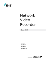
123 4 5 6 7 8 9 0
DirectIP™ Switch
DirectIP™
Gigabit PoE
Switch
Audio Out HDMI Monitor VGA Monitor
Alarm
Alarm Out
USB HDD USB ODD
Network
Camera (1-8)
Sensor (1-4)
IR Remote
Control
Mouse Network Connection
Network Video Recorder
Flash
Memory
Part 1 – Introduction

Part 1 – Introduction
12
Accessories
Upon unpackaging the product, check the contents inside to ensure that all the following accessories are
included.
123 4 5 6 7 8 9 0
DR-6100/4100 Series Power Cable Quick Guide
Operation Manual and IDIS Center
Program CD Optical USB Mouse IR Remote Control
Rack-mount Kit Assembly Screws for Adding Hard
Disk Drives SATA2 cables

Part 1 – Introduction
13
Overview
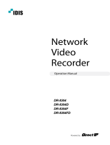
Front Panel
123 4 5 6 7 8 9 0
1 2 3 4 5 6 7 80
9
9
1Panic Recording
Button 2Alarm Button 3PTZ Button 4Layout Button
5Search Mode
Button 6Menu Button 7Camera Buttons 8
Arrow and
Playback Control
Buttons
9LEDs 0USB Ports
•Some buttons have more than one function.
•Remote control sensor is located on the far left side of the front panel. Ensure that the sensor remains unobstructed
at all times. If obstructed, the sensor might not be able to receive remote control signals.
•Placing a Wi-Fi, Bluetooth, or any other wireless communication device near the NVR may interfere with remote
control signal transmission.
•Access various windows and menus using a USB mouse as you would on a personal computer.
•For easier system configuration, a USB mouse is recommended.

Part 1 – Introduction
14
1 Panic Recording Button
Pressing Panic Recording
123 4 5 6 7 8 9 0
button displays the
icon and commences recording irrespective of
the current schedule.
Press the button again to deactivate Panic
Recording mode.
2 Alarm Button
Pressing the Alarm
123 4 5 6 7 8 9 0
button while the alarm has
been activated resets all NVR outputs, including the
built-in buzzer. Pressing the button while the alarm
is off displays the event log on the screen.
3 PTZ Button
Pressing the PTZ
123 4 5 6 7 8 9 0
button initiates PTZ mode,
allowing you to control PTZ cameras.
In PTZ mode, use the arrow buttons to move the
camera up, down, left, and right.
1
2
3
4
5
6
Zoom-In
1
2
3
4
5
6
Zoom-Out
1
2
3
4
5
6
Focus Near
1
2
3
4
5
6
Focus Far
1
2
3
4
5
6
Load preset window
1
2
3
4
5
6Save current position as a preset
4 Layout Button
Press the Layout
123 4 5 6 7 8 9 0
button to cycle through split
screen formats.
Single Screen > 2x2 > 3x3 > 4x4 > 5x5 > 6x6
5 Search Mode Button
Pressing the Search Mode
123 4 5 6 7 8 9 0
button initiates
Search mode, which will allow you to search for
and play back video recordings.
Pressing the Search Mode
123 4 5 6 7 8 9 0
button while in
Search mode returns the screen to Live mode.
6 Menu Button
Pressing the Menu
123 4 5 6 7 8 9 0
button while in Live mode
displays the Live menu.
Pressing the Menu
123 4 5 6 7 8 9 0
button while in Search mode
displays the Search menu on the top of the screen.
Press the button once more to close the menu.
Pressing and holding the Menu
123 4 5 6 7 8 9 0
button for 3
seconds while in Playback mode activates One-
Touch mode and displays the clip copy window.
7 Camera Button
Pressing the Camera button while in Live or
Playback mode displays images from the selected
camera in full screen. To select a camera whose
channel is made up of two digits, enter the digits in
sequence using the number keys.
8 Arrow and Playback Control Buttons
These buttons are used to select menus and
options.
Enter ($)
Button
Used to select options or to
register data entries.
Play/Pause
(") Buttons
Plays the video in normal speed
and displays r on the screen.
Press again during playback to
pause the video and display
on the screen.
Setup Menu
(u/d/l/r) Buttons: Moves the
focus up, down, left, or right.
(u/d) Buttons: Increases or
decreases values.
Playback
Mode
From paused state:
% Button: To the previous
screen
& Button: To the next screen
Button: Scans backward
through the video at a fast rate.
(press to cycle through x2, x3,
and x4)
! Button: Scans forward
through the video at a fast rate.
(press to cycle through x2, x3,
and x4)
9 LEDs
•Power LED: Lights up while the main unit is in
operation.
• Network LED: Flashes when linked remotely
over an ethernet.
• HDD LED: Flashes when data is being
written on the HDD or a video search is in
progress.
• eSATA LED: Flashes when connected to an
eSATA device.
• Panic LED: Flashes in red when Panic
Recording is in progress. (Panic button LED)
• Alarm LED: Lights up in red when an alarm
event occurs. (Alarm button LED)

Part 1 – Introduction
15
0 USB Ports
•Storage Device Connection
Connect an external USB hard drive or a USB
flash memory device to one of the USB ports
for use with the Clip Copy feature. The external
storage device should be placed as close to the
NVR as possible. It is recommended that you use
a connection cable that is no longer than 180cm
in length. Use the connection cable included with
your external storage device to connect the device
to one of NVR's USB ports. For more information
Clip Copy, refer to the Clip Copy on page 69.
•Peripheral Device Connection
Use the USB ports to connect peripherals such
as a USB mouse or a USB printer to the NVR.
You can also use a USB-to-serial converter and
connect multiple text-in devices to the NVR at
the same time. It is also possible to connect a
PostScript™ printer and print stills from video data
stored on the NVR. The NVR supports version 2.0
and above PostScript™ printers. In addition, it is
possible to print color images if you own a color
PostScript™ printer. Connect the printer to one of
NVR's USB ports. For more information on printing
video stills, refer to the Print on page 70.
•For USB flash memory devices, the NVR
supports the FAT32 file format only.
•This NVR supports PostScript™ printers only.
•This NVR does not include a printer cable.
If your printer does not support USB
connection, please purchase and use a USB-
to-parallel port cable.


Part 1 – Introduction
17
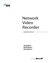
Rear Panel
<DR-6100 Series>
AUDIO IN
AUDIO OUT VGA OUT HDMI
eSATA
NETWORK
VIDEO IN
NC C NO AR I G RS -485
- +
A/1 A/2 A/3 A/4 G Tx Rx
RS -232
CAUTION : TO REDUCE THE RISK OF ELECTRIC SHOCK.
DO NOT REMOVE COVER (OR BACK).
NO USER-SERVICEABLE PARTS INSIDE.
REFER SERVICING TO QUALIFIED
SERVICE PERSONNEL.
1 3
2 4
CAUTION
RISK OF ELECTRIC SHOCK
DO NOT OPEN
A C E G
B D F H
100-240V~
1234 5 6 8
7
90
!
@
<DR-4100 Series>
AUDIO IN
AUDIO OUT VGA OUT
eSATA
NETWORK
VIDEO IN
NC C NO AR I G RS -485
- +
A/1 A/2 A/3 A/4 G Tx Rx
RS -232
CAUTION : TO REDUCE THE RISK OF ELECTRIC SHOCK.
DO NOT REMOVE COVER (OR BACK).
NO USER-SERVICEABLE PARTS INSIDE.
REFER SERVICING TO QUALIFIED
SERVICE PERSONNEL.
1
CAUTION
RISK OF ELECTRIC SHOCK
DO NOT OPEN
A C E G
B D F H
100-240V~
2
HDMI
12
34 5 6 8
7
90
!
@
1Audio Ports 2Factory Reset Button 3VGA Out Port
4HDMI Out Port 5eSATA Ports 6Alarm Connection Ports
7RS485 Port 8RS232 Port 9Network Port
0Video In Ports !Power In Port @Vent

Part 1 – Introduction
18
Rear Panel Connections
Monitor Connection
Connect to the VGA OUT or HDMI port.
AUDIO IN
AUDIO OUT
VGA OUT HDMI
eSATA
NETWORK
VIDEO IN
NC C NO AR I G RS -485
- +
A/1 A/2 A/3 A/4 G Tx Rx
RS -232
CAUTION : TO REDUCE THE RISK OF ELECTRIC SHOCK.
DO NOT REMOVE COVER (OR BACK).
NO USER-SERVICEABLE PARTS INSIDE.
REFER SERVICING TO QUALIFIED
SERVICE PERSONNEL.
1 3
2 4
CAUTION
RISK OF ELECTRIC SHOCK
DO NOT OPEN
A C E G
B D F H
100-240V~
Audio Connection
AUDIO IN
AUDIO OUT
VGA OUT HDMI
eSATA
NETWORK
VIDEO IN
NC C NO AR I G RS -485
- +
A/1 A/2 A/3 A/4 G Tx Rx
RS -232
CAUTION : TO REDUCE THE RISK OF ELECTRIC SHOCK.
DO NOT REMOVE COVER (OR BACK).
NO USER-SERVICEABLE PARTS INSIDE.
REFER SERVICING TO QUALIFIED
SERVICE PERSONNEL.
1 3
2 4
CAUTION
RISK OF ELECTRIC SHOCK
DO NOT OPEN
A C E G
B D F H
100-240V~
Connect the audio device to the AUDIO IN port and
speakers with a built-in amplifier to the AUDIO OUT
port. Use the AUDIO OUT port to listen to audio from
network cameras.
Use the AUDIO IN port to establish two-way
communication with cameras.
•This NVR does not feature a built-in audio amplifier
unit and therefore requires the user to purchase a
speaker system with a built-in amplifier separately.
It's possible to connect an amplified audio source
to the NVR, but microphones that do not have
a built-in amplifier will not function properly if
connected to the NVR directly. If this is the case,
connect the microphone to the NVR via a pre-
amp.
•Check your local laws and regulations on making
audio recordings.
Video Connection
AUDIO IN
AUDIO OUT VGA OUT HDMI
eSATA
NETWORK
VIDEO IN
NC C NO AR I G RS -485
- +
A/1 A/2 A/3 A/4 G Tx Rx
RS -232
CAUTION : TO REDUCE THE RISK OF ELECTRIC SHOCK.
DO NOT REMOVE COVER (OR BACK).
NO USER-SERVICEABLE PARTS INSIDE.
REFER SERVICING TO QUALIFIED
SERVICE PERSONNEL.
1 3
2 4
CAUTION
RISK OF ELECTRIC SHOCK
DO NOT OPEN
A C E G
B D F H
100-240V~
Connect network cameras to the NVR using RJ-45
cable (Cat5, Cat5e, or Cat6). In addition to cameras,
you can connect external hubs (Optional: DH-2112PF,
DH-2128PF) to form a network. The NVR recognizes
DirectIP™ network cameras automatically.
•For the external hub, we recommend using
an H port to enable functions such as camera
alignment.
•The orange LED on the left flashes if the
connected network is 10/100 BASE-T. The green
LED on the right flashes if the connected network
is 1000 BASE-T.
Network Connection
AUDIO IN
AUDIO OUT VGA OUT HDMI
eSATA
NETWORK
VIDEO IN
NC C NO AR I G RS -485
- +
A/1 A/2 A/3 A/4 G Tx Rx
RS -232
CAUTION : TO REDUCE THE RISK OF ELECTRIC SHOCK.
DO NOT REMOVE COVER (OR BACK).
NO USER-SERVICEABLE PARTS INSIDE.
REFER SERVICING TO QUALIFIED
SERVICE PERSONNEL.
1 3
2 4
CAUTION
RISK OF ELECTRIC SHOCK
DO NOT OPEN
A C E G
B D F H
100-240V~
This NVR is capable of connecting to networks via
an ethernet connector. Connect an RJ-45 cable
(Cat5, Cat5e, or Cat6) to the NVR's network port. It's
possible to operate and upgrade the NVR remotely
over a network. Fore more information on ethernet
connection setup, refer to Network Setup on page 57.
The orange LED on the left flashes if the connected
network is 10/100 BASE-T. The green LED on
the right flashes if the connected network is 1000
BASE-T.
eSATA Connection
Connect external hard drives to these ports.
AUDIO IN
AUDIO OUT VGA OUT HDMI
eSATA
NETWORK
VIDEO IN
NC C NO AR I G RS -485
- +
A/1 A/2 A/3 A/4 G Tx Rx
RS -232
CAUTION : TO REDUCE THE RISK OF ELECTRIC SHOCK.
DO NOT REMOVE COVER (OR BACK).
NO USER-SERVICEABLE PARTS INSIDE.
REFER SERVICING TO QUALIFIED
SERVICE PERSONNEL.
1 3
2 4
CAUTION
RISK OF ELECTRIC SHOCK
DO NOT OPEN
A C E G
B D F H
100-240V~
DR-4100 Series features 2 eSATA ports.

Part 1 – Introduction
19
Do not connect or disconnect an eSATA device
while the NVR is powered on. To connect an eSATA
device, first turn off the NVR and unplug the power
cable. Connect the eSATA device and then power
the NVR back on. To disconnect an eSATA device,
first turn off the NVR and unplug the power cable.
Turn off the eSATA device and then disconnect the
eSATA connection cable.
RS232 Connection
Connect an external device such as a POS unit to this
port.
AUDIO IN
AUDIO OUT VGA OUT HDMI
eSATA
NETWORK
VIDEO IN
NC C NO AR I G RS -485
- +
A/1 A/2 A/3 A/4 G Tx Rx
RS -232
CAUTION : TO REDUCE THE RISK OF ELECTRIC SHOCK.
DO NOT REMOVE COVER (OR BACK).
NO USER-SERVICEABLE PARTS INSIDE.
REFER SERVICING TO QUALIFIED
SERVICE PERSONNEL.
1 3
2 4
CAUTION
RISK OF ELECTRIC SHOCK
DO NOT OPEN
A C E G
B D F H
100-240V~
RS485 Connection
This NVR supports the RS485 half-duplex serial
communication protocol for connecting to external
devices such as POS units.
AUDIO IN
AUDIO OUT VGA OUT HDMI
eSATA
NETWORK
VIDEO IN
NC C NO AR I G RS -485
- +
A/1 A/2 A/3 A/4 G Tx Rx
RS -232
CAUTION : TO REDUCE THE RISK OF ELECTRIC SHOCK.
DO NOT REMOVE COVER (OR BACK).
NO USER-SERVICEABLE PARTS INSIDE.
REFER SERVICING TO QUALIFIED
SERVICE PERSONNEL.
1 3
2 4
CAUTION
RISK OF ELECTRIC SHOCK
DO NOT OPEN
A C E G
B D F H
100-240V~
Alarm Connection
Connect alarm connectors to these ports.
AUDIO IN
AUDIO OUT VGA OUT HDMI
eSATA
NETWORK
VIDEO IN
NC C NO AR I G RS -485
- +
A/1 A/2 A/3 A/4 G Tx Rx
RS -232
CAUTION : TO REDUCE THE RISK OF ELECTRIC SHOCK.
DO NOT REMOVE COVER (OR BACK).
NO USER-SERVICEABLE PARTS INSIDE.
REFER SERVICING TO QUALIFIED
SERVICE PERSONNEL.
1 3
2 4
CAUTION
RISK OF ELECTRIC SHOCK
DO NOT OPEN
A C E G
B D F H
100-240V~
Press down on the button and insert the cable into
the opening. Release the button and then pull on the
cable slightly to ensure it is held securely in place.
To disconnect the cable, press down on the button
again and pull the cable out.
•Alarm In 1 through 4
This NVR is capable of responding to event signals
from external alarm in devices. Connect mechanical or
electrical switches to Alarm In 1 through 4 and the G
(ground) connector. In order to be recognized by the
NVR, the signal from an alarm in device must be less
than 0.3V (Normally Open) and maintained for at least
0.5 seconds. The alarm in voltage range is 0V to 5V.
For more information on alarm in setup, refer to the
Alarm-In on page 54.
•G (Ground)
Connect alarm in or out's ground cable to the G
connector.
All connectors marked "G" are common connectors.
•NO (Relay Alarm Out)
This NVR is capable of activating/deactivating
buzzers, lights, and other external devices. Connect
a mechanical or electrical switch to NO and COM
connectors. Electrical specifications are 2A sync
at 125V AC and 1A sync at 30V DC. For more
information on alarm out setup, refer to the Alarm-
Out on page 57.
Connector Arrangement
AI1 through AI4 Alarm In 1 through 4
GGround
CRelay Common
NO/NC
Normally Open and Normally
Close Relay Alarm Out
(connected to C port)

Part 1 – Introduction
20
Power Cable Connection
Connect the power cable to this port. This NVR does
not feature a separate power on/off button and will
turn on the moment power is supplied.
AUDIO IN
AUDIO OUT VGA OUT HDMI
eSATA
NETWORK
VIDEO IN
NC C NO AR I G RS -485
- +
A/1 A/2 A/3 A/4 G Tx Rx
RS -232
CAUTION : TO REDUCE THE RISK OF ELECTRIC SHOCK.
DO NOT REMOVE COVER (OR BACK).
NO USER-SERVICEABLE PARTS INSIDE.
REFER SERVICING TO QUALIFIED
SERVICE PERSONNEL.
1 3
2 4
CAUTION
RISK OF ELECTRIC SHOCK
DO NOT OPEN
A C E G
B D F H
100-240V~
•Organize the power cable so that it will not cause
people to trip over or become damaged from
chairs, cabinets, desks, and other objects in the
vicinity. Do not run the power cable underneath a
rug or carpet.
•The power cable is grounded. Do not modify the
power plug even if your power outlet does not
have a ground contact.
•Do not connect multiple devices to a single power
outlet.
Factory Reset
AUDIO IN
AUDIO OUT
VGA OUT HDMI
eSATA
NETWORK
VIDEO IN
NC C NO AR I G RS -485
- +
A/1 A/2 A/3 A/4 G Tx Rx
RS -232
CAUTION : TO REDUCE THE RISK OF ELECTRIC SHOCK.
DO NOT REMOVE COVER (OR BACK).
NO USER-SERVICEABLE PARTS INSIDE.
REFER SERVICING TO QUALIFIED
SERVICE PERSONNEL.
1 3
2 4
CAUTION
RISK OF ELECTRIC SHOCK
DO NOT OPEN
A C E G
B D F H
100-240V~
Located next to the Audio Out port on the rear of the
NVR is a switch that, once activated, will reset the
NVR to all its initial factory settings.
A factory reset will clear all NVR settings configured
by the user.
You will need a straightened paper clip to access the
factory reset button.
1 Restart the NVR (turn off and then on).
2 Once the front panel LEDs start to flash, insert
a straightened paper clip into the factory reset
switch hole and press the switch.
3 Press and hold until you hear 2 beeps from the
NVR's internal buzzer.
4 All NVR settings will be returned to their factory
values once you remove the paper clip.
1/86