Gigabyte 3D Mars GZ-FA2CA-AJB User manual
- Category
- Computer cases
- Type
- User manual
This manual is also suitable for

GZ-FA2CA-AJS/AJB
English
User’s Manual
3D MARS

English
2
The following are not covered by the warranty:
1.Using the product incorrectly or in a manner other than the designed pur-
pose.
2.Nonobservance of the proper operation provided
3.Malfunction due to interference from other devices
4.Unapproved modification of the product
5.Consequential damage to other objects due to the product’s fault.
6.Malfunction arising from natural hazards E.g. earthquake, lightning, fire,
and floods.
7.The product’s warranty label has been removed or damaged.
8.The devices inside, including power supply, hard disk, CD-ROM drive, moth-
erboard, ventilator, etc, are not detached from the casing prior to transpor-
tation of the computer system, resulting in damage to the casing or other
computer-related devices.
9.Any loss/damage caused by failure to follow the installation process with in
the user manual.
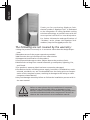
Failure to wear gloves during installation of computer
products may cause bodily harm or damage to your
devices. Incorrect connector installation may possibly burn
out the motherboard and other components. Be sure to
observe the instructions in the installation manual.
Thank you for purchasing Gigabyte Tech.
thermal product. Gigabyte Tech. is dedicated
to the integration of casing liquid/air-cooling
solution technology to provide users with the
most optimal solution for heat dissipation.
For further information and specifications of
“3D Mars” series, please visit Gigabyte Tech.
website. (http://www.gigabyte.com.tw)

3
English
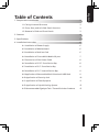
Table of Contents
1. Components Introduction 3
1-1 Casing’s Internal Structure 3
1-2 Front, Rear, and Left Side Panel Structure 3
1-3 Removal of Side and Front Panels 3
2. Features 4
3. Specifications 5
4. Installation Instruction 6
4-1 Installation of Power Supply 6
4-2 Installation of Motherboard 6
4-3 Installation of Add-on Card 6
4-4 Installation of Front Multi-Media I/O port 7
4-5 Connection of Fan Power Cable 8
4-6 Installation of 5.25” Front Device Bay 8
4-7 Installation of 3.5” Front Device Bay 9
4-8 Installation of 3.5” Internal Device Bay 9
4-9 Application of Removable/Dual Directional HDD Rack 9
4-10 Application of Security lock 10
4-11 Application of Foot Supports 11
4-12 Application of Liquid Cooling System 12
4-13 Recommended Gigabyte Tech. Thermal Solution Products 12

English
4
1
3
2
4
5
6
7
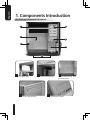
Power Supply Bay
1
PCI Tool-Free Fastener
2
Motherboard tray and
PCI Slot panel
3
5.25” Front Device Bay
4
3.5” Front Device Bay
5
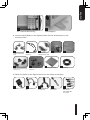
1. Components Introduction
1-1 Casing’s Internal Structure

5
English
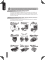
8. Accessory Box (Refer to the figures below for the attachments in the
accessory box)
Copper Stand Off
x 12
Power Extension
Cable x 2
3.5” Device
Thumbscrews x 20
Wire Clamp x 2
Motherboard Securing
Screw x 12
Power Supply Securing
screw x 4
Dust Remover Cloth Magnet Ring
Key x 2
a b c d
e
f
g
h i
9.Cable Kit ( Refer to the figures below for the cable connectors)
USB 2.0
Audio (HD & AC’
97)
IEEE1394 ( Multi-
connectors)
Power SW / Reset
SW / Power
LED / HDD LED
Connector
3-Pin Fan
Connector
a b c d
e
3.5” Internal Device Bay
6
Foot Support
7

English
6
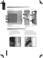
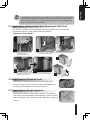
1-2 Front, Rear, and Left Side Panel Structure
1-3 Removal of Side and Front Panels
A-1 Left Side Panel
A-2 Latch
A-3 Security Lock
A-4 Ventilated Mesh / Transparent Side Panel
A.Left Side Panel
1
2
3
4
B.Front Panel
B-1 Power / Reset
Switches and LED
light
B-2 Front Multi-Media
I/O port
1
2
C-1 Dual Rear fans
C-2 LCS Tube Outlets
C.Rear Panel
1
2
1-3.1 To remove side panels:
1-3.1a Remove the 4 thumb
screws at the rear of the side
panel, and detach the side
panels.
1-3.2 To remove front panel:
1-3.2a Remove the left and
right side panels (see step 1-3.1
), release the 6 clamps that hold
the front panel onto the chassis.

7
English
C.Rear Panel
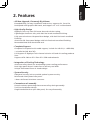
2. Features
- All New Upgrade, Extremely Big Volume
Extended Body, for easy installation and service, supports SLI, Cross Fire
Dual/Quad multi-graphic G80 cards, and support 12” x 13” motherboard.
- High Quality Design
Gigabyte Tech. top-class full tower thermal solution casing.
Lightweight aluminum alloy with hair-line brush anodized finishing.
Fully-open aluminum side panel door design, with hair-line brush anodized
finishing.
Aluminum 3D front panel design with hair-line brush anodized finishing.
Removable/Dual directional HDD rack.
- Complete Support
Complete front panel multi-media support, include 2 x USB 2.0, 1 x IEEE1394,
1 x Audio Set (HD & AC’97).
Full Support of Gigabyte Tech. thermal solution LCS and Air cooling products
lines.
Supports ATX / Micro ATX / Flex ATX / CEB motherboards.
- Integration of Cooling Technology
Aluminum alloy chassis for accelerating system cooling performance.
Dual right panel 8cm air intake fans to actively cool HDD.
Unique illuminated front air intake design.
- System Security
Side panel security lock to provide optimal system security.
Reinforced nickel-plated rear panel.
1.0mm reinforced aluminum structure.
- Convenience of assembly
Scratch-resistant processing that ensures safety during assembly.
Tool-free installation design.
Single handed latch to open side panel, for easy disassembly.

English
8
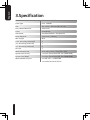
3.Specification
Model GZ-FA2CA-AJS/AJB
Case Type FULL TOWER
Size 205 x 522 x 565mm (W x H x D)
Front Bezel Material Aluminum
Color Silver/Black
Side Panel Ventilated Mesh / Transparent
Body Material Aluminum (1.0mm)
Net weight 8KG
5.25” drive bay (external) 5
3.5” drive bay (external) 1
3.5” drive bay (internal) 5
PCI slot 7
Motherboard size ATX / Micro ATX / Flex ATX / CEB
System Fan (Front) 1 x 12cm Silent Blue LED fan (1000 RPM)
System Fan (Rear) 2 x 12cm Silent Blue LED fan (1000 RPM)
Multi-Media I/O port 2 x USB 2.0 / 1 x IEEE1394
1 x Audio Set HD & AC’97

9
English
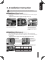
4. Installation Instruction
4-1 Installation of Power Supply
To facilitate the installation, it is recommended to set the chassis upright
on the table.
〔Required Tools: Power supply securing screw x 4〕
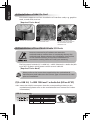
4-2 Installation of Motherboard
This chassis supports ATX / Micro ATX / Flex-ATX / CEB motherboards.
Please confirm the dimensions and fixing points of the motherboard prior
to installation.
〔Required Tools: Copper stand offs, Motherboard screws〕
Please follow the reference sections in order for installation
According to
motherboard
specifications, select
proper screw points,
screw in the copper
stand offs into the
corresponding points
on the motherboard.
2.1
Change the
motherboard I/O
bracket on the rear
panel (supplied by
the motherboard
manufacturer).
2.2
2.3
Motherboard
Code
name
Motherboard
screws
case
copper
post
ATX A1-A9 9 9
Micro ATX U1-U9 9 9
Flex-ATX F1-F6 6 6
E-ATX E1-E12 12 12
Secure the motherboard with the motherboard screws (refer to your
motherboard manual to check what type of motherboard you have).
1.1 1.2 1.3
Remove side panel (see step
1-3.1 on page 6). Place the
power supply unit into the case.
Secure the power supply with
the 4 securing screws.
When using a larger power
supply unit, Please disassemble
the cross bar by loosening
the securing screws. Fasten
the screws to secure the cross
bar after the power supply is
installed.

English
10
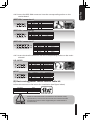
4-3 Installation of Add-On Card
This chassis supports tool-free installation of interface cards, e.g. graphics
cards, sound cards, and etc.
〔Required Tools: None〕
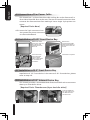
4-4 Installation of Front Multi-Media I/O Ports
The front panel includes (1) 2 x USB 2.0, 1 x IEEE 1394 and 1 x Audio Set (HD
or AC’97) / (2) Basic casing power switch control cable kit
〔Required Tools: None〕
(1)2 x USB 2.0, 1 x IEEE 1394 and 1 x Audio Set (HD or AC’97)
4-4.1 Insert the USB 2.0 connectors into the corresponding sockets on the
motherboard (please refer to the motherboard user manual for further
information)
3.1 3.2 3.3
Unlock the PCI slot retention
lock.
Remove the internally attached
dust proof PCI cover.
Insert the interface card
carefully into the expansion
slot and lock the PCI slot
retention lock.
Incorrect connection of sockets can cause the
motherboard to malfunction or completely destroy the
motherboard. Please observe the installation instructions
in the manual carefully as incorrect installations or
connection causing faults will void your warranty.
USB 2.0 connector
Pin Definition Pin Definition
1 Power 6 USB Dy+
2 Power 7 GND
3 USB Dx- 8 GND
4 USB Dy- 9
5 USB Dx+ 10 USB Over current
Please refer to the instructions supplied by the motherboard
manufacturer and make sure the correct type of connector is used
prior to installation.

11
English
4-4.2 Insert the IEEE 1394 connector into the corresponding socket on the
motherboard.
4-4.3 Insert the Audio connector into the corresponding socket on the moth-
erboard.
(2) Basic casing power switch control cable kit
Follow the connectors list below for installation (see figure below)
IEEE 1394 connector A
Pin Definition Pin Definition
1 TPA+ 6 TPB-
2 TPA- 7
3 GND 8 +12V
4 GND 9 +12V
5 TPB+ 10 GND
Pin Definition Pin Definition
1 TPA+ 6 TPB-
2 TPA- 7 +12V
3 GND 8 +12V
4 GND 9
5 TPB+ 10 GND
Pin Definition Pin Definition
1 +12V 9 +12V
2 +12V 10 +12V
3 TPA+ 11 TPA1+
4 TPA- 12 TPA1-
5 GND 13 GND
6 GND 14
7 TPB+ 15 TPB1+
8 TPB- 16 TPB1-
IEEE 1394 connector B
IEEE 1394 connector C
HD AUDIO
AC'97
Pin Definition Pin Definition
1
MIC2_L
6
FSENSE1
2
GND
7
FAUDIO_JD
3
MIC2_R
8
4
-ACZ_DET
9
LINE2_L
5
LINE2_R
10
FSENSE2
Pin Definition Pin Definition
1
MIC
6
NC
2
GND
7
NC
3
MIC Power
8
4
NC
9
Line Out(L)
5
Line Out(R)
10
NC
Connector Color
Reset SW
Green(+) / Wite(-)
Power SW
Orange(+) / White(-)
H.D.D. LED
Red(+) / White(-)
Different Motherboards have different installation areas,
specifications, screw holes and connectors. Please read the
motherboard user manual supplied by the motherboard
manufacturer.
A
B
C

English
12
4-5 Connection of Fan Power Cable
This chassis has 1 x 12cm silent blue LED cooling fan at the front and 2 x
12cm silent blue LED fans at the rear. There are internal connectors that
connects the front and rear fans making it into a single 3-pin power con-
nector.
〔Required Tools: None〕
4-5.1 Insert the 3-pin connector into
the system fan power connector
on the motherboard.
4-6 Installation of 5.25” Front Device Bay
4-7 Installation of 3.5” Front Device Bay
Installation of 3.5” front device is the same as 5.25” front devices, please
refer to step 4-6.
4-8 Installation of 3.5” Internal Device Bay
This chassis provides a removable/dual directional HDD rack to accommo-
date up to 5 hard disc drives.
〔Required Tools: Thumbscrews (4 per hard disc drive)〕
Detach the front
panel (see step 1-3.2
on page 6) and
remove the front
drive rail.
6.1
Remove the
corresponding EMI
plate and attach the
front panel onto the
chassis.
6.2
Secure the 5.25”
device with the
internal latch.
Refer to the figure
for installation
procedure.
6.3
Installation complete
6.4
Slide the HDD into
the rack and secure
the HDD with the
thumbscrews.
8.1 8.2
Lock
1
2

13
English
4-9 Application of Removable/Dual Directional HDD Rack
This chassis includes a removable/dual directional HDD rack for preferred
installation direction and optimal heat dissipation.
〔Required Tools: None〕
4-10 Application of Security Lock
This chassis includes a safety lock on the side panel.
Insert the key into the lock and rotate it 90 degrees ac-
cording to the diagram to lock and unlock it
4-11 Application of Foot Supports
This chassis consists of four foot supports for ensuring
the casing is firmly seated on the holding surface. Swivel
the foot support 90° according to the diagram to open or
retract.
In case the length of the power cable is not sufficient for installation
of the bottom HDDs, please use the power extension cable which
can be found inside the accessory box. Connect it according to the
type of connector of your HDD.
9 .1 9.2
4-9.1 Remove the thumbscrew
that secures the
removable HDD rack.
4-9.2 Unlock tool-free fastener of the removable HDD rack by
pushing it downwards.
A
4-9.3 Change the HDD rack directional alternating fastener on
top of the rack and align the arrows for desired direction.
(Dual Direction Only)
A
B
B

English
14
4-12 Application of Liquid Cooling System
This chassis fully supports Gigabyte Tech. 3D Galaxy series liquid cool-
ing system (also supports most of the liquid cooling systems currently
available). While installing the liquid cooling system, please refer to its
manual in advanced.
4-13 Recommended Gigabyte Tech. Thermal Solution Products.
It is recommended to use the following thermal products for optimal
heat dissipation with this chassis.
When moving or laying down the chassis, please swivel the foot
support to the closed position, to prevent bending and damage
-
 1
1
-
 2
2
-
 3
3
-
 4
4
-
 5
5
-
 6
6
-
 7
7
-
 8
8
-
 9
9
-
 10
10
-
 11
11
-
 12
12
-
 13
13
-
 14
14


Gigabyte 3D Mars GZ-FA2CA-AJB User manual
- Category
- Computer cases
- Type
- User manual
- This manual is also suitable for
Ask a question and I''ll find the answer in the document
Finding information in a document is now easier with AI
Related papers
-
Gigabyte Sumo Alpha Specification
-
Gigabyte 3DAURORA570S User manual
-
-
-
-
-
-
-
Gigabyte 230 User manual
-
Gigabyte Triton Owner's manual
Other documents
-
Apex SQ-311 Datasheet
-
Rosewill R7439K User manual
-
Apevia X-Qpack Installation guide
-
ENERMAX Staray Lite Datasheet
-
Cooler Master Cosmos Pure Specification
-
Cooler Master Cosmos 1010 Specification
-
Antec Nine Hundred User manual
-
Thermaltake MozartTX User guide
-
-
Antec SONATA DESIGNER UK Datasheet