Page is loading ...

18) Make wire connections (connectors not provided). Reference
chart below for correct connections and wire accordingly.
19) Raise canopy to ceiling.
20) Secure canopy in place by tightening threaded ring onto
screw collar loop.
21) To install bulbs, raise latch up on side of fixture with hinged
door. Pull door open.
22) Insert bulbs into sockets.
23) Close door. Lower latch inserting bottom of latch into hole in
channel on fixture.
1) To install glass panels: NOTE: Side Glass Panels (Quantity 3)
are larger than Door Glass Panel (Quantity 1).
Raise latch up on side of fixture with hinged door. Pull door
open. Carefully insert one glass panel into cage of fixture.
Tilt glass and fit top edge of glass into channel along top of
one side of cage. Carefully lower glass down and fit bottom
edge of glass panel into bottom channel on side of cage.
Repeat these steps for remaining glass panels.
2) Pass fixture wire through end of threaded pipe with hexnut.
Screw end of threaded pipe with hexnut into coupling on top
of fixture.
3) Pass fixture wire through tube. Slip tube down over threaded
pipe on top of fixture.
4) Lower ring down over top of fixture. Pass fixture wire through
hole in center of ring. Pass hole in center of ring over end of
threaded pipe protruding from tube on top of fixture.
5) Pass holes at ends of ring over ends of threaded studs on
sides of roof of fixture.
6) Thread one threaded cap onto each threaded stud. Tighten
threaded caps to secure ring to roof.
7) Pass fixture wire through hole in check ring. Slip check ring
down over end of threaded pipe protruding from top of ring.
8) Pass fixture wire though hole in bottom of loop. Thread loop
onto end of threaded pipe.
9) TURN OFF POWER.
IMPORTANT: Before you start, NEVER attempt any work
without shutting off the electricity until the work is done.
a) Go to the main fuse, or circuit breaker, box in your
home. Place the main power switch in the “OFF”
position.
b) Unscrew the fuse(s), or switch “OFF” the circuit breaker
switch(s), that control the power to the fixture or room
that you are working on.
c) Place the wall switch in the “OFF” position. If the fixture
to be replaced has a switch or pull chain, place those in
the “OFF” position.
10) Take threaded pipe from parts bag and screw in screw collar
loop a minimum of 6 mm (1/4”). Lock into place with hexnut.
11) Run another hexnut down threaded pipe almost touching
first hexnut. Now screw threaded pipe into mounting strap.
Mounting strap must be positioned with extruded thread
faced into outlet box. Threaded pipe must protrude out the
back of mounting strap. Screw third hexnut onto end of
threaded pipe protruding from back of mounting strap.
12) Connect mounting strap to outlet box.
13) Unscrew the threaded ring from screw collar loop. Take
canopy and pass over screw collar loop. Approximately one
half of the screw collar loop exterior threads should be
exposed. Adjust screw collar loop by turning assembly up or
down in mounting strap. Remove canopy.
14) After desired position is found, tighten both top and bottom
hexnuts up against the bottom and top of the mounting
strap.
15) Slip canopy over screw collar loop and thread on threaded
ring. Attach chain (with fixture connected) to bottom of
screw collar loop. Unscrew threaded ring, let canopy and
threaded ring slip down.
16) Weave electrical wire and ground wire through chain links no
more than 3 inches apart. Pass wire through threaded ring,
canopy, screw collar loop, threaded pipe and into outlet box.
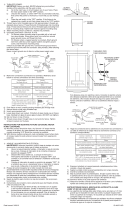
17) Grounding instructions: (See Illus. A or B).
A) On fixtures where mounting strap is provided with a
hole and two raised dimples. Wrap ground wire from
outlet box around green ground screw, and thread into
hole.
B) On fixtures where a cupped washer is provided. Attach
ground wire from outlet box under cupped washer and
green ground screw, and thread into mounting strap.
If fixture is provided with ground wire. Connect fixture
ground wire to outlet box ground wire with wire connector
(not provided.) after following the above steps. Never
connect ground wire to black or white power supply wires.
MOUNTING STRAP
ABRAZADERA DE MONTAJE
HEXNUT
TUERCA HEXAGONAL
THREADED PIPE
TUBO ROSCADO
CANOPY
ESCUDETE
THREADED RING
ANILLO ROSCADO
Date Issued: 1/17/14 IS-43259-US
GREEN GROUND
SCREW
CUPPED
WASHER
A
B
OUTLET BOX
GROUND
FIXTURE
GROUND
DIMPLES
WIRE CONNECTOR
(NOT PROVIDED)
OUTLET BOX
GROUND
GREEN GROUND
SCREW
FIXTURE
GROUND
Connect Black or
Red Supply Wire to:
Connect
White Supply Wire to:
Black White
*Parallel cord (round & smooth) *Parallel cord (square & ridged)
Clear, Brown, Gold or Black
without tracer
Clear, Brown, Gold or Black
with tracer
Insulated wire (other than green)
with copper conductor
Insulated wire (other than green)
with silver conductor
*Note: When parallel wires (SPT I & SPT II)
are used. The neutral wire is square shaped
or ridged and the other wire will be round in
shape or smooth (see illus.)
Neutral Wire
SCREW COLLAR LOOP
OJAL DE COLLAR ROSCADO
SEE OTHER SIDE FOR SPANISH TRANSLATIONS.
VEA EL OTRO LADO DE TRADUCCIONES AL ESPAÑOL.
We’re here to help 866-558-5706
Hrs: M-F 9am to 5pm EST
LOOP
ANILLO
RING
ANILLO
TUBE
TUBO
THREADED PIPE
TUBO ROSCADO
THREADED CAP
TAPA ROSCADO
THREADED STUD
ESPÁRRAGO
ROSCADO
GLASS PANEL
PANEL DE VIDRIO
CHECK RING
ANILLO DE SEGURIDAD
Glass Panel A
Door Panel
Glass Panel B
Side Panel
Panel de vidrio A
Panneau de la
puerta
Panel de vidrio B
Panel lateral

1) To install glass panels: NOTE: Side Glass Panels (Quantity 3)
are larger than Door Glass Panel (Quantity 1).
Raise latch up on side of fixture with hinged door. Pull door
open. Carefully insert one glass panel into cage of fixture.
Tilt glass and fit top edge of glass into channel along top of
one side of cage. Carefully lower glass down and fit bottom
edge of glass panel into bottom channel on side of cage.
Repeat these steps for remaining glass panels.
2) Pass fixture wire through end of threaded pipe with hexnut.
Screw end of threaded pipe with hexnut into coupling on top
of fixture.
3) Pass fixture wire through tube. Slip tube down over threaded
pipe on top of fixture.
4) Lower ring down over top of fixture. Pass fixture wire through
hole in center of ring. Pass hole in center of ring over end of
threaded pipe protruding from tube on top of fixture.
5) Pass holes at ends of ring over ends of threaded studs on
sides of roof of fixture.
6) Thread one threaded cap onto each threaded stud. Tighten
threaded caps to secure ring to roof.
7) Pass fixture wire through hole in check ring. Slip check ring
down over end of threaded pipe protruding from top of ring.
8) Pass fixture wire though hole in bottom of loop. Thread loop
onto end of threaded pipe.
9) TURN OFF POWER.
IMPORTANT: Before you start, NEVER attempt any work
without shutting off the electricity until the work is done.
a) Go to the main fuse, or circuit breaker, box in your
home. Place the main power switch in the “OFF”
position.
b) Unscrew the fuse(s), or switch “OFF” the circuit breaker
switch(s), that control the power to the fixture or room
that you are working on.
c) Place the wall switch in the “OFF” position. If the fixture
to be replaced has a switch or pull chain, place those in
the “OFF” position.
10) Take threaded pipe from parts bag and screw in screw collar
loop a minimum of 6 mm (1/4”). Lock into place with hexnut.
11) Run another hexnut down threaded pipe almost touching
first hexnut. Now screw threaded pipe into mounting strap.
Mounting strap must be positioned with extruded thread
faced into outlet box. Threaded pipe must protrude out the
back of mounting strap. Screw third hexnut onto end of
threaded pipe protruding from back of mounting strap.
12) Connect mounting strap to outlet box.
13) Unscrew the threaded ring from screw collar loop. Take
canopy and pass over screw collar loop. Approximately one
half of the screw collar loop exterior threads should be
exposed. Adjust screw collar loop by turning assembly up or
down in mounting strap. Remove canopy.
14) After desired position is found, tighten both top and bottom
hexnuts up against the bottom and top of the mounting
strap.
15) Slip canopy over screw collar loop and thread on threaded
ring. Attach chain (with fixture connected) to bottom of
screw collar loop. Unscrew threaded ring, let canopy and
threaded ring slip down.
16) Weave electrical wire and ground wire through chain links no
more than 3 inches apart. Pass wire through threaded ring,
canopy, screw collar loop, threaded pipe and into outlet box.
17) Connect fixture ground wire to outlet box ground wire with
wire connector. (Not provided.) Never connect ground wire
to black or white power supply wire.
18) Make wire connections (connectors not provided). Reference
chart below for correct connections and wire accordingly.
Date Issued: 1/17/14 IS-43259-CB
Connect Black or
Red Supply Wire to:
Connect
White Supply Wire to:
Black White
*Parallel cord (round & smooth)
*Parallel cord (square & ridged)
Clear, Brown, Gold or Black
without tracer
Clear, Brown, Gold or Black
with tracer
Insulated wire (other than green)
with copper conductor
Insulated wire (other than green)
with silver conductor
*Note: When parallel wires (SPT I & SPT II)
are used. The neutral wire is square shaped
or ridged and the other wire will be round in
shape or smooth (see illus.)
Neutral Wire
INSTRUCTIONS
For Assembling and Installing Fixtures in Canada
Pour L’assemblage et L’installation Au Canada
SEE OTHER SIDE FOR CANADIAN FRENCH TRANS-
LATIONS.
VOIR L’AUTRE CÔTÉ POUR LES CANADIENS TRA-
DUCTIONS EN FRANÇAIS.
We’re here to help 866-558-5706
Hrs: M-F 9am to 5pm EST
MOUNTING STRAP
PATTE DE FIXATION
HEXNUT
ECROU HEXAGONAL
THREADED PIPE
TUBE FILETÉ
SCREW COLLAR LOOP
COLLIER-ÉCROU
CANOPY
CACHE
THREADED RING
BAGUE FILETÉE
LOOP
ANNEAU
RING
ANNEAU
THREADED STUD
GOUJON FILETÉ
Glass Panel A
Door Panel
Glass Panel B
Side Panel
THREADED PIPE
TUBE FILETÉ
CHECK RING
ANNEAU DE RETENUE
TUBE
TUBE
THREADED CAP
BOUCHON FILETÉ
GLASS PANEL
PANNEAU
VERRE
Panneau verre A
Panneau de porte
Panneau verre B
Panneau latéral
19) Raise canopy to ceiling.
20) Secure canopy in place by tightening threaded ring onto
screw collar loop.
21) To install bulbs, raise latch up on side of fixture with hinged
door. Pull door open.
22) Insert bulbs into sockets.
23) Close door. Lower latch inserting bottom of latch into hole in
channel on fixture.
/