Page 4
MODEL 751
USE AND CARE USE AND CARE
WARNING: DISCONNECT ELECTRICAL POWER SUPPLY AND
LOCK OUT SERVICE PANEL BEFORE RELAMPING, CLEANING,
OR SERVICING THIS UNIT.
RELAMPING
Pull grille assembly away from ceiling.
Squeeze the grille assembly’s mounting springs together, and
removegrilleasemblyfromhousingtoexposesocketforrelamp-
ing.
Insertlamp(100wattmaximum)intothesocket.NOTE: Lampmust
be purchased separately.
Replacegrilleassemblyatagainsttheceilingafterrelamping.
CLEANING
Pull grille assembly away from ceiling.
Squeeze the grille assembly’s mounting springs together, and
remove grille asembly from housing for cleaning.
Clean grille and lens assembly using a mild soap and water solution.
Assemblies with wood frames should not be immersed.
Replacegrilleassemblyatagainsttheceilingaftercleaning.
MOTOR LUBRICATION
The motor is permanently lubricated. Do not oil or disassemble
motor.
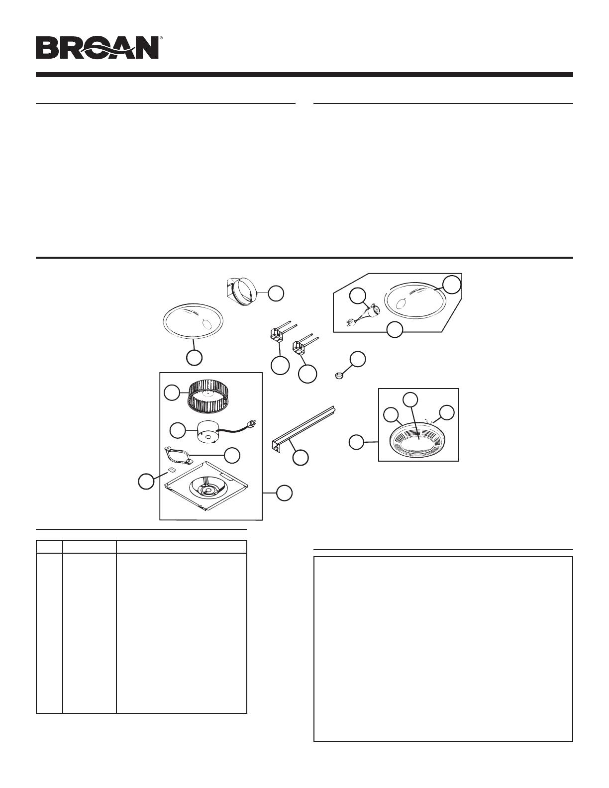
SERVICE PARTS
WARRANTY
KEY PART NO. DESCRIPTION
1 97017704 Power Unit Assembly
2 100599-000 Motor
3 32787-000 MotorIsolationMount
4 32788-000 GroundClip
5 100603-000 BlowerWheel
6 86000-000 ReectorAssembly
7 85979-000 LampSocket
8 30652-000 DuctAdapterAssembly
9 44388-000 HangerBar
10 97017702 Grille Assembly
11 99111406 Grille
12 61753-000 Lens
13 57000-000 GrilleSpring(2req.)
14 99260575 Acorn Nut
15 99270981 LightReceptacle
16 99270982 Fan Receptacle
17 101049-000 Reector
* Not shown assembled.
Orderreplacementpartsby“PARTNO.”-notby“KEYNO.”
99043079H
12
14
11
12
13
9
17
6
7
15
16
4
5
1
3
10
8
2
6
7
17
15
16
BROAN-NUTONE ONE YEAR LIMITED WARRANTY
Broan-NuTonewarrantstotheoriginalconsumerpurchaserofitsproductsthatsuchproducts
will be free from defects in materials or workmanship for a period of one year from the date of
originalpurchase.THEREARENOOTHERWARRANTIES,EXPRESSORIMPLIED,INCLUD-
ING,BUTNOTLIMITEDTO,IMPLIEDWARRANTIESOFMERCHANTABILITYORFITNESS
FORAPARTICULARPURPOSE.
Duringthisone-yearperiod,Broan-NuTonewill,atitsoption,repairorreplace,withoutcharge,
any product or part which is found to be defective under normal use and service.
THISWARRANTYDOESNOTEXTENDTOFLUORESCENTLAMPSTARTERSANDTUBES.
This warranty does not cover (a) normal maintenance and service or (b) any products or parts
which have been subject to misuse, negligence, accident, improper maintenance or repair (other
thanbyBroan-NuTone),faultyinstallationorinstallationcontrarytorecommendedinstallation
instructions.
Thedurationofanyimpliedwarrantyislimitedtotheone-yearperiodasspeciedfortheexpress
warranty. Some states do not allow limitation on how long an implied warranty lasts, so the above
limitation may not apply to you.
BROAN-NUTONE’SOBLIGATIONTOREPAIRORREPLACE,ATBROAN-NUTONE’SOPTION,
SHALLBETHEPURCHASER’SSOLEANDEXCLUSIVEREMEDYUNDERTHISWARRANTY.
BROAN-NUTONESHALLNOTBELIABLEFORINCIDENTAL,CONSEQUENTIALORSPECIAL
DAMAGESARISINGOUTOFORINCONNECTIONWITHPRODUCTUSEORPERFORMANCE.
Somestatesdonotallowtheexclusionorlimitationofincidentalorconsequentialdamages,so
theabovelimitationorexclusionmaynotapplytoyou.
Thiswarrantygivesyouspeciclegalrights,andyoumayalsohaveotherrights,whichvaryfrom
state to state. This warranty supersedes all prior warranties.
Toqualifyforwarrantyservice,youmust(a)notifyBroan-NuToneattheaddressortelephone
numberbelow,(b)givethemodelnumberandpartidenticationand(c)describethenatureof
any defect in the product or part. At the time of requesting warranty service, you must present
evidence of the original purchase date.
Broan-NuToneLLCHartford,Wisconsinwww.broan.com800-558-1711