Page is loading ...

ENGLISH
ENGLISH
EN
This instruction sheet will provide you with information required to safely own
and operate your Little Giant WRSC-6 kit. This unit is designed to pump
wastewater from laundry trays, washing machines, sinks, or dehumidifiers. It is
not designed to pump raw sewage, fluids other than water, or fluids with solids.
The inlet screen will remove many solids over 1/8” diameter, but large amounts
of solids can clog screen and result in pump failure. Maximum fluid temperature
is 125° F. Unit is designed to fit under most sinks so in many cases it is not
necessary to recess the unit into the floor.
This instruction sheet covers the standard models in this pump series. This form
is applicable to other models in this series not listed by catalog number in the
replacement parts list section of this pamphlet. If the catalog number of your
pump is not listed in the replacement parts section, then exercise caution when
ordering replacement parts. Always give the catalog number of your pump
when ordering replacement parts.
The Little Giant unit you have purchased is of the highest quality workmanship
and material. It has been engineered to give you long and reliable service.
Little Giant pumps are carefully packaged, inspected, and tested to ensure safe
operation and delivery. When you receive your pump, examine it carefully to
determine that there are no broken or damaged parts that may have occurred
during shipment. If damage has occurred, make notation and notify the firm
where you purchased the pump. They will assist you in replacement or repair,
if required.
READ INSTRUCTIONS CAREFULLY BEFORE ATTEMPTING TO INSTALL,
OPERATE OR SERVICE THE LITTLE GIANT PUMP. KNOW THE PUMP
APPLICATION, LIMITATIONS, AND POTENTIAL HAZARDS. PROTECT
YOURSELF AND OTHERS BY OBSERVING ALL SAFETY INFORMATION.
FAILURE TO COMPLY WITH INSTRUCTIONS COULD RESULT IN
PERSONAL INJURY AND/OR PROPERTY DAMAGE! RETAIN INSTRUCTIONS
FOR FUTURE REFERENCE.
SAFETY GUIDELINES
1. Make certain that the unit is disconnected from the power source before
attempting to service or remove any component!
2. Do not use to pump flammable or explosive fluids such as gasoline, fuel
oil, kerosene, etc. Do not use in explosive atmospheres or hazardous
locations as classified by NEC, ANSI/NFPA70. Pump should be used with
liquids compatible with pump component materials.
3. Do not handle the pump with wet hands or when standing on a wet or
damp surface or in water.
4. Do not pull the pump out of the water by the power cord when the pump
is operating or connected to power source.
5. This pump is supplied with a grounding conductor and/or grounding-type
attachment plug. To reduce the risk of electrical shock, be certain that it is
connected to a properly grounded grounding type receptacle.
6. The National Electric Code requires a ground fault circuit interrupter (GFCI)
be installed in the branch circuit supplying fountain equipment, pools, etc.
7. In any installations where property damage and/or personal injury might
result from an inoperative or leaking pump due to power outages,
discharge line blockage, or any other reason, a backup system(s) and/or
alarm should be used.
8. Support pump and piping during assembly and when installed. Failure to do
so may cause piping to break, pump to fail, motor bearing failures, etc.
9. The pump motor is equipped with an automatic resetting thermal protector
and may restart unexpectedly. Protector tripping is an indication of motor
overloading as a result of excessively high or low voltage, inadequate
wiring, incorrect motor connections, or a defective motor or pump.
10. If pump is an oil-filled pump, the motor housing is filled with a dielectric
lubricant at the factory for optimum motor heat transfer and lifetime
lubrication of the bearings. Use of any other lubricant could cause damage
and void the warranty. This lubricant is non-toxic; however, if it escapes the
motor housing, it should be removed from the surface quickly by placing
newspapers or other absorbent material on the water surface to soak it up,
so aquatic life is undisturbed.
ELECTRICAL CONNECTIONS
1. Check the pump label for proper voltage required. Do not connect to
voltage other than that shown.
2. If pump is supplied with a 3-prong electrical plug, the third prong is to ground
the pump to prevent possible electrical shock hazard. DO NOT REMOVE the
third prong from the plug. A separate branch circuit is recommended. Do not
use an extension cord. Do not cut plug from the cord. If the plug is cut or the
cord is shortened, then this action will void the warranty.
3. If the cord is equipped with stripped lead wires, such as on 230 V models, be
sure that the lead wires are connected to a power source correctly. The (green/
yellow) wire is the ground. The (blue or white) and the (brown or black) are live.
CONSULT INSTRUCTION SHEET ILLUSTRATIONS FOR PROPER
ASSEMBLY AND DISASSEMBLY OF YOUR LITTLE GIANT PUMP.
4. Check local electrical and building codes before installation. The installation
must be in accordance with their regulations as well as the most recent
National Electrical Code (NEC).
5. Plug into a grounded receptacle with vent tube pointed down. Vent tube
must remain unobstructed for proper pump operation.
6. If installed in basement, plug connection should be four feet or more above floor,
especially if basement floods. Be sure electrical connections cannot be reached by
rising water. Under no circumstances should outlet box or receptacle be located
where it may become flooded or submerged by water.
OPERATION
1. Determine proper location for unit. Unit should be located so that inlet is gravity-fed.
Unit will not draw water up from a lower level. Position and level basin. Keep basin
away from any item that could puncture basin. Position selected should be
convenient to inlet, discharge and vent piping and electrical supply.
2. Plumb inlet. Using proper adapter, plumb discharge to basin cover fitting. Use a
P-trap and a union next to the basin. Use pipe joint compound and hand tighten
only on plastic fittings. A 1-1/2" MNPT x 2" slip pipe adapter is provided if a 2" inlet
is required. See "Typical Installation."
3. Plumb discharge. Using proper adapter, plumb discharge to basin cover fitting. Use
a swing check valve as close as possible to top of basin cover and union. Be sure
check valve is installed in proper flow direction. If check valve is installed backwards,
no water will flow out of unit. Be sure discharge piping is sealed with pipe joint
compound and that lift height of pump is not exceeded. Hand tighten only on plastic
fitting. A 1-1/2" MNPT x 2" slip pipe adapter is provided if a 2" discharge is required.
4. Plumb vent. Plumb vent using 2" threaded pipe to fitting in basin cover. Use pipe
joint compound on threads and hand tighten only on plastic fittings. The basin must
be vented in accordance with state and local codes. A 2" MNPT x 1-1/2" Slip pipe
adapter is provided if a 1-1/2" vent is required.
THIS UNIT WILL NOT OPERATE WITHOUT PROPER VENTING. CAUTION: Do not
use a mechanical vent with this product. A mechanical vent will cause improper
operation of the automatic switch.
5. Test Unit. Connect power cord to electrical supply as stated in ELECTRICAL
CONNECTIONS. Secure power cord to piping
with ties or tape. Fill unit with
water through inlet. Pump should turn on with 4" to 7" (10.2 - 17.8 cm) of
water in tank, and turn off when 1½" to 3½" (3 - 8 cm) of water is left in tank.
See Pump Troubleshooting Guide if problems occur.
1
WRSC-6
63(&,),&$7,216&$5$&7e5,67,48(67(&+1,48(6(63(&,),&$&,21(6
Model No.
Modèle No.
N° de Modelo
Catalog No.
Rèfèrence
Catalogue
Cataloga
Número
Volts
Volts
Voltios
Hertz
Hertz
Hertz
Amps
Ampères
Amperios Watts
Watts
Watts
Gallons per hour (GPH) at ht.
Litres par huere
Litros por hora
Shutoff (FT.)
Hauteur à
débit nul
A Válvula
Cerrda
PSI
Kg/cm2S R
5' 10' 15'
WRSC-6 506065 115 60 13 9 720 2750 1750 750 18 7.8
WRSC-6 506066 230 50 7 5 720 2580 1050 — 12 5.2
Franklin Electric Co., Inc.
Oklahoma City, OK
)D[
www.LittleGiantPump.com

FR
FRANÇAIS
FR
Cette liste de directives vous fournit les renseignements nécessaires pour
utiliser une WRSC-6 Little Giant en toute sécurité. Cette pompe est conçue pour
pomper les eaux usées des bacs à linge sale, des machines à laver, des éviers
ou des déshumidificateurs.
Elle n’est pas conçue pour pomper des eaux d’égout, des liquides autres que
de l’eau ou des liquides comportant des solides. L’écran d’entrée retiendra
beaucoup de particules dépassant 1/8 po de diamètre; toutefois, une grande
quantité de matières solides peut bloquer l’écran et causer une panne de la
pompe. La température du liquide ne doit pas dépasser 125°F. La pompe est
conçue pour aller sous la majorité des éviers; il est donc dans la plupart des
cas inutile de l’encastrer dans le plancher.
La présente feuille d’instructions décrit les modèles standard de cette série de
pompe. Ce document s’applique également à d’autres modèles de cette série
qui ne sont pas indiqués par leur numéro de catalogue dans la section des
pièces de remplacement du présent document. Si tel était le cas avec votre
pompe, il faudra être particulièrement attentif au moment de commander des
pièces. Toujours donner le numéro de catalogue de votre pompe lors de la
commande de pièces.
Votre nouvelle pompe Little Giant a été fabriquée avec les meilleurs matériaux
et avec le plus grand soin. Elle a été conçue pour foncionner bien et
longtemps.
Les pompes Little Giant sont soigneusement emballées, et testées pour assurer
une livraison et un fonctionnement sans problèmes. Lorsque vous recevez
votre pompe, examinez-la attentivement pour vous assurer qu’il n’y a pas eu de
pièce cassée ou endommagée pendant l’acheminement. S’il y a eu des dégats,
prenez-en note et signalez-le au magasin où vous avez acheté la pompe. Ils
vous aideront pour le remplacement ou la réparation, si nécessaire. Cette
pompe est conçue pour pomper de l’eau. NE POMPEZ PAS de produit
chimique, de solvant, d’eau salée, ou de liquides épais tels que des huiles ou
de la graisse.
BIEN LIRE LES INSTRUCTIONS AVANT D’INSTALLER, DE FAIRE
FONCTIONNER OU D’ENTRETENIR LA POMPE LITTLE GIANT. IL FAUT
CONNAÎTRE L’APPLICATION, LES LIMITESET LES DANGERS POTENTIELS
'( /$ 3203( 3527e*(=9286 (7 /(6 $875(6 (1 5(63(&7$17
7287(6 /(6 1250(6 '( 6e&85,7e /( 1215(63(&7 '(6
INSTRUCTIONS PEUT CAUSER DES ATTEINTES AUX PERSONNES OU À
/$35235,e7e*$5'(5/(35e6(17'2&80(1732855e)e5(1&(
8/7e5,(85(
SERVICE INSTRUCTIONS
MAKE CERTAIN THE UNIT IS DISCONNECTED FROM THE POWER
SOURCE BEFORE ATTEMPTING TO SERVICE OR REMOVE ANY
COMPONENT!
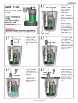
1. To clean inlet filter remove the 4 cover plate screws (21), cover plate (19),
seal ring (item 28), and screen (item 27). Clean inlet screen using a mild
detergent and water. Examine o-ring and if deformed, replace with new
o-ring. See replacement parts list.
2. Sediment may build up in basin causing pump to operate improperly.
Remove 10 1/4-20 screws (item 21) from cover. Remove cord grommet and
loosen cords to allow slack and then remove cover.
Remove pump and clean basin using a mild detergent and water.
Reassemble in reverse order. Torque screws (item 21) 18–20 in–lbs.
3. If pump alignment plate is removed, it must be reinstalled per plate
alignment diagram (Figure 1).
4. Sediment or lint can clog pump and cause improper operation. If necessary,
remove pump and pull off the pressed-in screen, clean using a mild
detergent and water, and reinstall. Plastic pump base may also be removed
to clean around impeller and inside base. Remove the six base screws and
clean base using a mild detergent and water. Do not remove impeller.
When reinstalling base, be sure seal ring is seated properly in groove and
torque screws to 12-17 in.-lbs. See pump manual for other information. For
any other pump repair, return the pump to a Little Giant authorized service
center.
5. This unit is permanently lubricated. Oiling is not required. Do not, in any
case, open the sealed portion of the unit or remove housing screws.
6. Remove screws (item 4) that hold base to volute and clean impeller and
volute passage. Do not use strong solvents on impeller.
%HVXUHLPSHOOHUWXUQVIUHHO\DIWHUFOHDQLQJ:$51,1*'21275(029(
IMPELLER. REMOVAL OF IMPELLER REQUIRES SPECIAL TOOLS
AND IS TO BE DONE ONLY BY AN AUTHORIZED SERVICE CENTER.
8. When reinstalling base, be sure seal ring is seated properly in groove and
torque screws (item 4) to 10–15 in.–lbs.
9. DO NOT REMOVE MOTOR HOUSING COVER. WARRANTY IS VOID IF
MOTOR HOUSING COVER, IMPELLER OR SEALS HAVE BEEN REMOVED.
ANY REPAIR ON MOTOR MUST BE DONE BY AN AUTHORIZED LITTLE
GIANT SERVICE CENTER.
10. Be certain power cord is in good condition with no nicks or cuts.
1
2
Position the alignment plate inside the basin as shown. This will
position the mounting holes properly when installing the basin
cover. Any other position will prevent assembly of cover.
Placer la plaque de l’alignement à l’intérieur du réservoir, tel
qu’illustré. Ainsi, les trous de montage seront correctement alignés
au moment de la pose du couvercle du réservoir. Tout autre
positionnement de la plaque ne permettra pas la pose du couvercle.
Coloque la placa de alineacion dentro del depósito como se ilustra.
Esto permitirá la alineación apropiada de los agujeros de montaje
cuando instale la cubierta del depósito. Cualquier otra posición no
permitirá armar la cubierta.
Ensure mounting hole (1) lines up with locating rib (2) on inside of
basin.
Le trou de montage (1) s’aligne avec une nervure (2) de
positionnement située à l’intérieur du réservoir.
Los agujeros de montaje (1) se alinean con un saliente de ubicación
(2) dentro del depósito.
Figure 1
PLATE ALIGNMENT DIAGRAM
',$*5$00('(/·$/,*1(0(17'(/$3/$48(
DIAGRAMA DE ALINEACION DE LA PLACA
2

Mounting hole lines up with a locating rib on the inside of the
EDVLQ/HWURXGHPRQWDJHV·DOLJQHDYHFXQHQHUYXUHGH
SRVLWLRQQHPHQWVLWXpHjO·LQWpULHXUGXUpVHUYRLU/RVDJXMHURVGH
PRQWDMHVHDOLQHDQFRQXQVDOLHQWHGHXELFDFLyQGHQWURGHO
GHSyVLWR
3RVLWLRQWKHSXPSORFDWLQJSODWHLQVLGHWKHEDVLQDVVKRZQ7KLV
ZLOODOORZSURSHUDOLJQPHQWRIPRXQWLQJKROHVZKHQLQVWDOOLQJWKH
EDVLQFRYHU$Q\RWKHUSRVLWLRQZLOOQRWDOORZDVVHPEO\RIFRYHU
3ODFHUODSODTXHjO·LQWpULHXUGXUpVHUYRLUWHOTX·LOOXVWUp$LQVLOHV
WURXVGHPRQWDJHVHURQWFRUUHFWHPHQWDOLJQpVDXPRPHQWGHOD
SRVHGXFRXYHUFOHGXUpVHUYRLU7RXWDXWUHSRVLWLRQQHPHQWGHOD
SODTXHQHSHUPHWWUDSDVODSRVHGXFRXYHUFOH&RORTXHOD
ERPEDSRQLHQGRODSODFDGHQWURGHOGHSyVLWRFRPRVHLOXVWUD
(VWRSHUPLWLUiODDOLQHDFLyQDSURSLDGDGHORVDJXMHURVGHPRQWDMH
FXDQGRLQVWDOHODFXELHUWDGHOGHSyVLWR&XDOTXLHURWUDSRVLFLyQQR
SHUPLWLUiDUPDUODFXELHUWD
Figure 3
REPLACEMENT PARTS LIST
ITEM NO.
PART
NO. DESCRIPTION 47<
1 108101 +DQGOHSXPS3RLJQpHSRPSH0DQLYHODERPED 1
2 928004 6HDOULQJ$QQHDXG·pWDQFKpLWp$QLOORGHHVWDQFDPLHQWR 1
3 108034
Pump base, manXDOEOXH3RPSHPDQXHOGHEDVHEOHXH
%RPEDPDQXDOGHEDse azul
1
4 909021
Screw/wasKHU[µ9LVURQGHOOH1[
7RUQLOOR\DUDQdela de #10-24 x 1/2" de pulgada
5
5 108082 6FUHHQLQWDNH)LOWUHG·DGPLVVLRQ5HMLOODWRPD 1
6 928028 6HDOULQJ$QQHDXG·pWDQFKpLWp$QLOORGHHVWDQFDPLHQWR 1
7 108051
HousLQJDVVHPE\DXWRPDWLF·Y&DUWHUHQVHPEOHWXUELQH
$XWRPDWLTXHP9&XELHUWDHQVDPEODMHGHLPSXOVRUDXWRPiWLFR
2.4 m (115 V)
1
7 108052
HoXVLQJDVVHPE\DXWRPDWLF·Y&DUWHUHQVHPEOHWXUELQH
$XWRPDWLTXHP9&XELHUWDHQVDPEODMHGHLPSXOVRUDXWRPiWLFR
2.4 m (230 V)
1
8 108202 %UDFNHWVZLWFK3DWWH'·DWWDFKH&RPPXWDWHXU6RSRUWH,QWHUUXSWRU 1
9 951961
Lead wireDVVHPEO\$VVHPEODJHILOVSOXPEpV&RQMXQWRGHKLORV
conductores
1
10 924001
O-ring, %XQD1-RLQWWRULTXH%XQD1-XQWDWyULFD
Buna-N, 2-007
2
11 950322 6ZLWFKPLQLDWXUH&RPPXWDWHXUPLQLDWXUH,QWHUUXSWRUPLQLDWXUH 1
12 901529
SFUHZPDFKLQH²[µ9LVPpcanique #10–24 x 1/4”
7RUQLOORSDUDPHWDOHVGH[GHSXOJDGD
1
13 902404
Screw, tap #8–18 [µ9LVWDUDXGpH1[7RUQLOORURVFD
macho #8-18 x 3/8" de pulgada
1
14 108125 'LDSKUDJP'LDSKUDJPH'LDIUDJQD 1
15 108055
CoYHUDXWRPDWLFVZLWFKKRXVLQJ&RXYHUFle, boîtier du contacteur
DXWRPDWLTXH&XELHUWDGHODFDMDGHOLQWHUUXSWRUDXWRPiWLFR
1
16 909027
ScrHZZDVKHU²[µ9LVURQdelle N° #10-24 x 1-3/4"
7RUQLOOR\DUDQGHODGH[GHSXOJDGD
4
17 921023
:DVKHUORFN5RQGHOOHYHUURXLOODJH$UDQGHODGHVHJXULGDG
#10
1
18 924047
2ULQJ%XQD1-RLQWWRULTXH%XQD1-XQWDWyULFD
Buna-N, 2-131
1
19 113132 &RYHUSODWHVFUHHQ&RXYHUFOHSODTXHJULOOH&XELHUWDGHSODFDUHMLOOD 1
20 113130 %DVLQFRYHU5pVHUYRLUFRXYHUFOH'HSyVLWRFXELHUWD 1
21 901709 6FUHZµ²[µ9LVµ[µ7RUQLOORµ[µ 14
22 924065 6HDOULQJ$QQHDXG·pWDQFKpLWp$QLOORGHHVWDQFDPLHQWR 1
23 113229 %DVLQ5pVHUYRLU'HSyVLWR 1
24 113024 'LVFKDUJHSLSH5HIRXOHPHQWWX\DX'HVFDUJDWXER 1
25 506160
3XPS&,$0/Y3RPSH&,$0/Y%RPED&,$0/
(115 v)
1
25 506161
3XPS&,$0/Y3RPSH&,$0/Y%RPED&,$0/
(230 v)
1
26 925016 &RUGJURPPHW3DVVHILO$UDQGHODDLVODQWHGHFRUGyQ 1
27 113131 ,QWDNHVFUHHQ'·DGPLVVLRQILOWUH7RPDUHMLOOD 1
28 924066
O-ring, BXQD1-RLQWWRULTXH%XQD1-XQWDWyULFD
Buna-N, 2-339
1
29 113135
Alignment plate ( 6HHSDJH3ODTue d’alignement (Montré sur la page
3ODWRGHDOLQHDFLyQ0RVWUDGRHQODSiJLQD
1
LIMITED WARRANTY
THIS WARRANTY SETS FORTH THE COMPANY’S SOLE OBLIGATION AND PURCHASER’S EXCLUSIVE REMEDY FOR DEFECTIVE
PRODUCT.
Franklin Electric Company, Inc. and its subsidiaries (hereafter “the Company”) warrants that the products accompanied by this
warranty are free from defects in materials or workmanship of the Company that exist at the time of sale by the Company and which
occur or exist within the applicable warranty period. Any distributor, sub-distributor, recipient, end-user and/or consumer agrees
that by accepting the receipt of the products, the distributor, sub-distributor, recipient, end user and/or consumer expressly agrees
to be bound by the terms of the warranty set forth herein.
I. APPLICABLE WARRANTY PERIOD
The products accompanied by this warranty shall be covered by this Limited Warranty for a period of 24 months from the date of
original purchase by the consumer. In the absence of suitable proof of purchase date, the warranty period of this product will begin
to run on the product's date of manufacture.
II. INSTRUCTIONS APPLICABLE TO THIS LIMITED WARRANTY
1. Consumers wishing to submit a warranty claim must return the products accompanied by this warranty to the point of purchase
for warranty consideration.
2. Upon discovery of a defect, any personal injury, property damage or any other type of resulting damage, if applicable, shall be
reasonably mitigated to the extent possible.
3. At its discretion, the Company may inspect products either at its facilities, or in the field, and after determination of a warranty claim, will, at its
option, repair or replace defective parts. Repaired or replaced parts will be returned freight prepaid by the Company.
4. This warranty policy does not cover any labor or shipping charges. The Company shall not be liable for any costs or charges
attributable to any product testing, maintenance, installation, repair or removal, or for any tools, supplies, or equipment needed
to install, repair, or remove any product.
III. LIMITATIONS APPLICABLE TO THIS LIMITED WARRANTY
THIS WARRANTY DOES NOT APPLY TO ANY OF THE FOLLOWING:
1. Brushes, impeller or cam on models with brush-type motors and/or flex-vane impellers.
2. Any product that is not installed, applied, maintained and used in accordance with the Company's published instructions,
applicable codes, applicable ordinances and/or with generally accepted industry standards.
3. Any product that has been subject to misuse, misapplication, neglect, alteration, accident, abuse, tampering, acts of God (including
lightning), acts of terrorism, acts of war, fire, improper storage or installation, improper use, improper maintenance or repair, damage or
casualty, or to an excess of the recommended maximums as set forth in the product instructions.
4. Any product that is operated with any accessory, equipment, component, or part not specifically approved by the Company.
5. Use of replacement parts not sold by the Company, the unauthorized addition of non-Company products to other Company
products, and the unauthorized alteration of Company products.
6. Products damaged by normal wear and tear, normal maintenance services and the parts used in connection with such service,
or any other conditions beyond the control of the Company.
7. Any product that has been used for purposes other than those for which it was designed and manufactured.
8. Any use of the product where installation instructions and/or instructions for use were not followed.
9. Products connected to voltage other than indicated on nameplate.
3URGXFWVZKHUHWKHSXPSZDVH[SRVHGWRDQ\RIWKHIROORZLQJVDQGJUDYHOFHPHQWJUHDVHSODVWHUPXGWDUK\GURFDUERQVK\GURFDUERQ
derivatives (oil, gasoline, solvents, etc.) or other abrasive or corrosive substances.
11. Products in which the pump has been used to pump or circulate anything other than fresh water at room temperature.
12. Products in which the pump was allowed to operate dry (fluid supply cut off).
13. Products in which the sealed motor housing has been opened or the product has been otherwise dismantled by customer.
14. Products in which the cord has been cut to a length of less than three feet.
The Company reserves the right at any time, and from time to time, to make changes in the design and/or improvements upon its product
without thereby imposing any obligation upon itself to make corresponding changes or improvements in or upon its products already
manufactured and/or previously sold. The Company further reserves the right to substitute parts or components of substantially equal
quality in any warranty service required by operation of this Limited Warranty.
This written Limited Warranty is the entire warranty authorized and offered by the Company. There are no warranties or
representations beyond those expressed in this document.
THIS WARRANTY AND REMEDY IS IN LIEU OF ALL OTHER WARRANTIES AND REMEDIES INCLUDING WITHOUT LIMITATION,
WARRANTIES OF MERCHANTABILITY AND/OR FITNESS FOR A PARTICULAR PURPOSE, WHICH ARE HEREBY SPECIFICALLY
DISCLAIMED AND EXPRESSLY EXCLUDED. CORRECTION OF NON-CONFORMITIES, IN THE MANNER AND FOR THE PERIOD OF TIME
AS SET FORTH ABOVE, SHALL CONSTITUTE FULFILLMENT OF ALL LIABILITY OF THE COMPANY TO THE PURCHASER WHETHER
BASED ON CONTRACT, NEGLIGENCE, OR OTHERWISE.
7

1
INTRODUCTION
EN
This instruction sheet provides you with the information required
to safely own and operate your product. Retain these instructions
for future reference.
The product you have purchased is of the highest quality
workmanship and material, and has been engineered to give you
long and reliable service. This product has been carefully tested,
inspected, and packaged to ensure safe delivery and operation.
Please examine your item(s) carefully to ensure that no damage
occurred during shipment. If damage has occurred, please
contact the place of purchase. They will assist you in replacement
or repair, if required.
READ THESE INSTRUCTIONS CAREFULLY BEFORE
ATTEMPTING TO INSTALL, OPERATE, OR SERVICE
YOUR PRODUCT. KNOW THE PRODUCT’S APPLICATION,
LIMITATIONS, AND POTENTIAL HAZARDS. PROTECT
YOURSELF AND OTHERS BY OBSERVING ALL SAFETY
INFORMATION. FAILURE TO COMPLY WITH THESE
INSTRUCTIONS COULD RESULT IN PERSONAL INJURY AND/
OR PROPERTY DAMAGE!
SAFETY GUIDELINES
WARNING: To reduce the risk of electrical shock, remove the plug
from the outlet before servicing this pump.
Read all instructions and safety guidelines thoroughly. Failure to
follow the guidelines and the instructions could result in serious
injury and/or property damage.
Check local electrical and building codes before installation. The
installation must be in accordance with their regulations.
During normal operation the pump is immersed in water. Also,
during rain storms, water may be present in the surrounding area
of the pump. Use caution to prevent bodily injury when working
near the pump. Remove the plug from the outlet before touching,
servicing, or repairing the pump. To minimize possible fatal
electrical shock hazard, use extreme care when changing fuses.
Do not stand in water while changing fuses or insert your finger
into fuse socket.
Do not operate the pump in a dry basin. This will cause the pump
to become extremely hot, causing burns if touched and/or damage
to the pump.
Do not oil the motor. The pump housing is sealed. A high grade
dielectric oil devoid of water has been put into the motor housing
at the factory. Use of other oil could cause serious electric shock
and/or permanent damage to the pump.
This pump’s motor housing is filled with a dielectric lubricant at the
factory for optimum motor heat transfer and lifetime lubrication of
the bearings. Use of any other lubricant could cause damage and
void the warranty. This lubricant is non-toxic; however, if it escapes
the motor housing, it should be removed from the surface quickly
by placing newspapers or other absorbent material on the water
surface to soak it up, so aquatic life is undisturbed.
WARNING: RISK OF ELECTRIC SHOCK! This pump is supplied
with a grounding conductor and grounding-type attachment plug.
To reduce the risk of electric shock, be certain that it is connected
only to a properly grounded, grounding-type receptacle.
ELECTRICAL CONNECTIONS
This pump is supplied with a 3 prong electrical plug. The third
prong is to ground the pump to prevent possible electric shock
hazard. Do not remove the third prong from the plug. A separate
branch electrical circuit is recommended. Do not use an extension
cord.
INSTALLATION
1. Clean any debris from sump pit and set pump in center of pit.
A solid bottom will prevent clogging of the pump from sand
and dirt.
2. Connect discharge piping and run it to the nearest sewer or
surface outlet. Use pipe joint compound at all connections.
These pumps can be piped to discharge into the house
drainage system, to a dry well, splash block, or to a storm
drain, depending on local plumbing codes. The discharge pipe
should be as short as possible and contain as few elbows as
possible. The discharge pipe should be the same diameter
as the discharge size to reduce pipe friction losses. Smaller
pipe will restrict capacity and reduce pump performance. This
pump comes with 1½" female thread discharge and 1¼" FNPT
reducing bushing.
3. Always install a union in the discharge line, just above the
sump pit, to allow for easy removal of the pump for cleaning or
repair.
4. In situations where the piping is long, the vertical discharge
is above 7 or 8 feet, or a small pit has been provided, use of
a check valve is recommended to prevent backflow of water
into the sump. When a check valve is used, drill a relief hole
(1/8" or 3/16" diameter) in the discharge pipe. This hole should
be located below the floor line between the pump discharge
and the check valve. Unless such a relief hole is provided, the
pump could air lock and will not pump water even though it will
run.
5. Tape pump and switch cords to discharge line with electrician’s
tape. This will protect the cords from damage and will prevent
power cords from interfering with float.
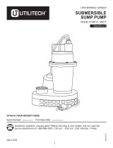
6. Connect the power cord to an outlet, vent tube down (Figure 1).
7. TEST THE PUMP AFTER ALL CONNECTIONS HAVE BEEN
MADE. Run water into sump. Do not attempt to operate the
pump without water; this will damage the seals and bearings
and could result in permanent damage to the pump. Fill sump
to normal ON level and allow pump to remove water to the
normal OFF level (Figure 2).
8. Place cover over sump. This cover will prevent solid debris
from filling the pit, prevent odors, and guard against accidental
injury.
BIG JOHN
®
SUBMERSIBLE
PUMP
6-CIA
Franklin Electric Co., Inc.
P. O. Box 12010
Oklahoma City, OK 73157-2010
405.947.2511 • Fax: 405.947.8720
www.LittleGiantPump.com

3
Figure 2 - Typical Installation

5
Figure 3 - Replacement Parts
REPLACEMENT PARTS
Item
No.
Part
No.
Description Qty.
1 108101 Handle, pump 1
2 928004 Seal ring 1
3 108029 Pump base, air bleed, blue 1
4 909021 Screw/washer #10-24 x 1/2” 5
5 108082 Screen, intake 1
6 928028 Seal ring 1
7 108049 Housing assembly, automatic, 8' 1
8 108202 Bracket switch 1
9 951961 Lead wire assembly 1
10 924001 O-ring 2
11 950323 Switch, miniature 1
12 599026 AD-6 reducer adaptor 1
13 902404 Screw, tap #8-18 x 3/8" 1
14 108125 Diaphragm 1
15 108055 Cover, automatic switch housing 1
16 909027 Screw/washer #10-24 x 1-3/4" 4
17 921023 Washer, #10 lock 1
18 901529 Screw, machine #10-24 x 1/4" 1

7
LIMITED WARRANTY
Your Little Giant product is guaranteed to be in perfect condition when it
leaves our factory. It is warranted against defective materials and workmanship
for a period of 24 months from date of purchase or 30 months from date of
manufacture, whichever occurs first. In the absence of other suitable proof of the
purchase date, the effective date of this warranty will be based upon the date of
manufacture plus two years.
Any product that should fail for either of the above two reasons and is still within
the warranty period will be repaired or replaced at the option of Little Giant as
the sole remedy of buyer. For our customers in the CONTINENTAL UNITED
STATES: Please return the defective unit, postage paid, to the factory at 301
N. MacArthur, Oklahoma City, OK 73127-6616. All defective product returned
under warranty will be fully inspected to determine the cause of failure before
warranty is approved.
For our customers located elsewhere; it is not economical, due to duties
and freight, to return the pump to the factory for inspection. Please return
the defective unit to any authorized distributor or dealer with a brief written
explanation of the problem. If there are no apparent signs of customer abuse,
unit will be repaired or replaced. If dispute arises over replacement of the pump,
the distributor or dealer is to segregate such items and hold for inspection by
a representative of Little Giant or notify factory with details of the problem for
factory disposition and settlement of warranty claim.
DISCLAIMER: THE FOREGOING WARRANTY IS AN EXCLUSIVE WARRANTY
IN LIEU OF ANY OTHER EXPRESS WARRANTIES. ANY IMPLIED WARRANTIES
(INCLUDING, BUT NOT LIMITED TO ANY IMPLIED WARRANTY OF
MERCHANTABILITY OR FITNESS FOR A PARTICULAR PURPOSE) TO THE
EXTENT EITHER APPLIES TO A PUMP SHALL BE LIMITED IN DURATION TO
THE PERIODS OF THE EXPRESS WARRANTIES GIVEN ABOVE.
Warranty will be VOID if any of the following conditions are found:
1. Sealed motor housing opened.
2. Product connected to voltage other than indicated on nameplate.
3. Cord cut off to a length less than three feet.
4. Pump allowed to operate dry (fluid supply cut off).
5. Pump used to circulate anything other than fresh water at approximately
room temperature.
6. Product abuse by customer.
Any oral statements about the product made by the seller, the manufacturer, the
representatives or any other parties, do not constitute warranties, shall not be relied
upon by the user and are not part of the contract for sale. Seller’s and manufacturer’s
only obligation, and buyer’s only remedy, shall be the replacement and/or repair
by the manufacturer of the product as described above. NEITHER SELLER NOR
THE MANUFACTURER SHALL BE LIABLE FOR ANY INJURY, LOSS OR DAMAGE,
DIRECT, INCIDENTAL OR CONSEQUENTIAL (INCLUDING, BUT NOT LIMITED
TO INCIDENTAL OR CONSEQUENTIAL DAMAGES FOR LOST PROFITS, LOST
SALES, INJURY TO PERSON OR PROPERTY, OR ANY OTHER INCIDENTAL OR
CONSEQUENTIAL LOSS), ARISING OUT OF THE USE OR THE INABILITY TO USE
THE PRODUCT AND THE USER AGREES THAT NO OTHER REMEDY SHALL BE
AVAILABLE TO IT. Before using, the user shall determine the suitability of the product
for the intended use, and user assumes all risk and liability whatsoever in connection
therewith.
Some states and countries do not allow limitations on how long an implied
warranty lasts or the exclusion or limitation of incidental or consequential
damages, so the above limitations or exclusions may not apply to you. This
warranty gives you specific legal rights, and you may also have other rights
which vary from state to state and country to country.
The National Electric Code (in the USA) and similar codes in other countries
require a Ground Fault Circuit Interrupter (GFCI) to be installed in the branch
circuit supplying fountain equipment rated above 15 volts. 115 volt GFCI’s (with
various cord lengths) are in stock, and we recommend each pump be used
with a GFCI.
GARANTIE LIMITÉE
La présente garantit que votre pompe Little Giant est en parfaite condition à sa
sortie de l’usine. La pompe est garantie contre tout défaut de matériau ou de
fabrication pendant une période de 24 mois à partir de la date d'achat, ou 30
mois à partir de la date de fabrication, selon le premier terme atteint. Si aucune
preuve acceptable de la date d'achat originale, la durée de cette garantie sera
de deux ans à compter de la date de fabrication.
Tout produit encore garanti qui serait défectueux pour l’une des deux raisons
sus-mentionnées sera réparé ou remplacé à la discrétion du fabricant. L’acheteur
n’aura pas d’autre recours. Pour nos clients aux ÉTATS-UNIS (territoire
continental seulement): Veuillez retourner l’article défectueux suffisamment
affranchi à l’usine à l’adresse suivante 301 North MacArthur Blvd., Oklahoma
City, OK 73127-6616. Tous les produits garantis retournés feront l’objet d’une
inspection détaillée afin de déterminer si la défectuosité est couverte par la
garantie. Pour les clients à l’extérieur des États-Unis : étant donné les frais
de douane et de transport, il n’est pas économique de retourner la pompe à
l’usine pour inspection. Expédier la pompe ainsi qu’une brève description du
problème à tout distributeur ou détaillant autorisé. Si elle ne présente aucun
signe apparent d’une mauvaise utilisation, elle sera remplacée ou réparée. S’il
y a conflit sur la nécessité de remplacer la pompe, le distributeur ou le détaillant
devra garder celle-ci et, soit la fera inspecter par un représentant de Little Giant,
soit avisera l’usine du problème afin de connaître la décision de celle-ci et le
règlement de la réclamation.
DÉNÉGATION: LA GARANTIE ÉNONCÉE DANS LES PRÉSENTES EST
EXCLUSIVE ET REMPLACE TOUTE AUTRE GARANTIE EXPRESSE OU
IMPLICITE; CELA COMPORTE, MAIS NON EXCLUSIVEMENT, TOUTE GARANTIE
IMPLICITE D’APTITUDE À LA COMMERCIALISATION OU D’APTITUDE
PARTICULIÈRE, POUVANT S’APPLIQUER À UNE POMPE PROVEN. DE
PLUS, ELLE NE S’APPLIQUE QUE DURANT LA PÉRIODE DE COUVERTURE
PRÉCISÉE CI-DEVANT.
La présente garantie sera ANNULÉE si:
1. Le boîtier scellé du moteur a été ouvert;
2. Le branchement à une tension autre que celle indiquée sur la plaque du
fabricant a été effectué;
3. Le fil d’alimentation a été coupé à une longueur inférieure à 0,91 m (trois
pieds);
4. La pompe a tourné à vide (l’alimentation en liquide a été coupée);
5. La pompe a été utilisée pour faire circuler des liquides autres que de l’eau
fraîche, des huiles légères ou d’autres liquides non corrosifs et ce, à la
température ambiante;
6. La pompe a été mal utilisée.
Toute déclaration sur la pompe faite oralement par le vendeur, le fabricant, le
représentant ou par toute autre partie ne constitue pas une garantie et, par
conséquent, ne peut servir à l’utilisateur. De plus, une telle déclaration ne peut,
en aucun cas, faire partie du contrat de vente. L’unique obligation du vendeur
et du fabricant, et l’unique recours de l’acheteur, est le remplacement ou la
réparation de la pompe selon les modalités décrites précédemment. NI LE
VENDEUR NI LE FABRICANT NE PEUVENT ÊTRE TENUS RESPONSABLES DE
TOUTE BLESSURE, TOUTE PERTE, OU TOUT DOMMAGE DIRECT, INDIRECT
OU ACCESSOIRE (INCLUANT, MAIS NON EXCLUSIVEMENT, LES VENTES OU
PROFITS PERDUS, LES ATTEINTES AUX PERSONNES OU À LA PROPRIÉTÉ
OU TOUTE AUTRE PERTE INDIRECTE OU ACCESSOIRE) RÉSULTANT DE
L’UTILISATION OU DE L’INCAPACITÉ D’UTILISATION DE LA POMPE, ET
L’ACHETEUR CONVIENT QU’IL NE DISPOSE D’AUCUN AUTRE RECOURS.
L’acheteur doit s’assurer que la pompe convient à l’usage projeté; il assume aussi
tout risque et toute responsabilité relativement à cet usage.
Certaines juridictions ne permettent pas la limitation de la durée d’une garantie
ou l’exclusion ou la limitation de responsabilité pour des dommages indirects
ou accessoires. Par conséquent, il est possible que la limitation ou l’exclusion
indiquée précédemment puisse ne pas être applicable. Cette garantie vous
donne des droits particuliers et peut-être d’autres, dépendamment des
juridictions en vigueur.
Le code national de l’électricité et autres codes semblables d’autres pays
exigent l’installation d’un interrupteur avec mise à la terre (GFI) sur le circuit
d’alimentation de la fontaine pour toute installation dont la tension est
supérieure à 15 volts. Nous offrons de tels interrupteurs (avec différentes
longueurs de fil) et nous recommandons que chaque pompe soit reliée à un
interrupteur de ce type.
GARANTIA LIMITADA
El producto que Little Giant le ofrece está garantizado a estar en perfectas
condiciones al momento de salir de la fábrica. El producto está garantizado
contra materiales y fabricación defectuosa por un período de 24 meses a partir
de la fecha de compra o 30 meses a partir de la fecha de fabricación, lo que
ocurra primero. En ausencia de otra prueba apropiada de la fecha de compra,
la fecha de vigencia de esta garantía se basará en la fecha de manufactura,
más dos años.
Cualquier producto que falle por alguna de las dos razones anteriores y que
esté dentro del período de garantía será reparado o reemplazado a opción
de Proven y éste será el único remedio del comprador. Para nuestros clientes
en los ESTADOS UNIDOS CONTINENTALES: Por favor, devolver la unidad
defectuosa, con el porte pagado, a la fábrica en 301 North MacArthur Blvd.,
Oklahoma City, OK 73127-6616. Todo producto defectuoso devuelto bajo la
garantía será cuidadosamente inspeccionado para determinar la causa de la
falla antes de aprobar la garantía. Para nuestros clientes ubicados en otros
lugares; no es económico devolver la bomba a la fábrica para que ésta sea
inspeccionada, debido a los impuestos y al flete. Por favor, devuelva la unidad
defectuosa a cualquier distribuidor o vendedor autorizado con una breve
explicación por escrito del problema. Si no existen señas aparentes de abuso
por parte del cliente, la unidad será reemplazada o reparada. Si se produce
una disputa sobre el reemplazo de la bomba, el distribuidor o vendedor
debe separar los artículos y retenerlos para que sean inspeccionados por un
representante de Little Giant o avisarle a la fábrica de los detalles del problema
para que la fábrica disponga de las acciones necesarias y resuelva el reclamo
de la garantía.
DESAUTORIZACION: LA GARANTIA ANTERIOR ES UNA GARANTIA EXCLUSIVA
EN LUGAR DE CUALQUIER OTRA GARANTIA EXPRESA. CUALQUIER

INTRODUCTION
EN
This instruction sheet provides you with the information required
to safely own and operate your product. Retain these instructions
for future reference.
The product you have purchased is of the highest quality work-
manship and material, and has been engineered to give you
long and reliable service. This product has been carefully tested,
inspected, and packaged to ensure safe delivery and operation.
Please examine your item(s) carefully to ensure that no damage
occurred during shipment. If damage has occurred, please con-
tact the place of purchase. They will assist you in replacement or
repair, if required.
READ THESE INSTRUCTIONS CAREFULLY BEFORE
ATTEMPTING TO INSTALL, OPERATE, OR SERVICE
YOUR PRODUCT. KNOW THE PRODUCT’S APPLICATION,
LIMITATIONS, AND POTENTIAL HAZARDS. PROTECT
YOURSELF AND OTHERS BY OBSERVING ALL SAFETY
INFORMATION. FAILURE TO COMPLY WITH THESE
INSTRUCTIONS COULD RESULT IN PERSONAL INJURY
AND/OR PROPERTY DAMAGE!
DESCRIPTION
This unit is designed to pump wastewater from laundry trays,
washing machines, sinks, or dehumidifiers. It is not designed to
pump raw sewage, fluids other than water, or fluids with solids.
Inlet screen will remove many solids over 1/8” diameter, but large
amounts of solids can clog screen and result in pump failure.
Maximum fluid temperature is 125°F. Unit is designed to fit under
most sinks, so in many cases it is not necessary to recess the unit
into the floor.
ITEMS TO PURCHASE
NOTE: Some state or local codes require all electrical and/or
plumbing connections to be made by a licensed contractor. It is
the customer’s responsibility to determine codes involved and
to comply with these codes. If user can install unit, items to
purchase are:
1. Inlet piping with trap and union. (Basin cover has 1-1/2” FNPT
fitting.)
2. Discharge piping with swing check valve and union. (Basin
cover has 1-1/2” FNPT fitting.)
3. Vent piping. (Basin cover has 2” FNPT fitting.)
SAFETY GUIDELINES
1. CAUTION: To reduce the risk of electric shock, pull plug
before servicing this pump.
2. Read all instructions and safety guidelines thoroughly. Failure
to follow the guidelines and the instructions could result in
serious bodily injury and/or property damage.
3. Check local electrical and building codes before installation.
The installation must be in accordance with these regulations.
4. During normal operation the pump is immersed in water. Use
caution to prevent bodily injury when working near the pump:
a. Remove plug from the receptacle prior to touching, servic-
ing, or repairing the pump.
b. To minimize possible fatal electrical shock hazard, use
extreme care when changing fuses. Do not stand in water
while changing fuses or insert your finger into fuse socket.
ELECTRICAL CONNECTIONS
All wiring must meet local codes, and a licensed electrical
contractor is recommended. The pump is supplied with a 3-prong
vented plug. Plugs must be plugged into a grounded receptacle
and vent tube must remain unobstructed for proper pump
operation. Pump should be on a separate circuit with fuse or
circuit breaker and ground fault circuit interrupter (GFCI). Be sure
electrical supply matches pump nameplate data. Do not use
extension cord. If installed in basement, plug connection should
be 4’ or more above floor, especially if basement floods. Be sure
electrical connections cannot be reached by rising water. Under
no circumstances should outlet box or receptacle be located
where it may become flooded or submerged by water.
INSTALLATION
All plumbing must meet local codes. A licensed plumbing con-
tractor is recommended. All fixtures connected to the WRS-6
Basin Kit must be vented according to state and local codes.
1. Determine proper location for unit. Locate unit so that inlet
is gravity-fed. Unit will not draw water up from a lower level.
Position and level basin. Keep basin away from any item that
could puncture basin. Position selected should be convenient
to inlet, discharge, and vent piping, and electrical supply.
2. Plumb inlet. Using 1-1/2” threaded pipe, plumb inlet to basin
cover fitting. Use a P-trap and a union next to the basin. Use
pipe joint compound and hand tighten only on plastic fittings.
Do not reduce below 1-1/2” piping.
3. Plumb discharge. Using 1-1/2” threaded pipe, plumb discharge
to basin cover fitting. Use a swing check valve no more than
3” from top of basin cover and a union. Be sure check valve is
installed in proper flow direction.
If check valve is installed backwards, no water will flow out
of unit. Be sure discharge piping is sealed with pipe joint
compound and that lift height of pump is not exceeded. Hand
tighten only on plastic fittings.
4. Plumb vent. Plumb vent using 2” threaded pipe to fitting in
basin cover. Use pipe joint compound on threads and hand
tighten only on plastic fittings. The basin must be vented in
accordance with state and local codes. The vent is essential for
proper switch operation and must not be omitted or restricted.
CAUTION: Do not use a mechanical vent with this product.
A mechanical vent will cause improper operation of the auto-
matic switch.
5. Test unit. Connect power cord to electrical supply as stated in
ELECTRICAL CONNECTIONS section. Secure power cord to
piping with ties or tape. Fill unit with water through inlet. Pump
should turn on with 7”–10” of water in tank, and turn off when
1”–3” of water is left in tank.
MAINTENANCE
WARNING: Before performing any maintenance, shut off water inlet
and disconnect power cord from supply outlet. Pump may become
hot during operation. Allow pump to cool before servicing.
Basin Screen: Remove 4 1/4-20 screen cover plate screws, plastic
cover plate, seal ring, and screen. Clean inlet screen using a mild
detergent and water. Examine O-ring and if deformed, replace
with new O-ring. See replacement parts table.
1
WRS-6
Wastewater
Removal System
with 6-CIA Pump
Franklin Electric Co., Inc.
P. O. Box 12010
Oklahoma City, OK 73157-2010
405.947.2511 • Fax: 405.947.8720
www.LittleGiantPump.com
CustomerService-[email protected]

Basin: Sediment may build up in basin causing pump to oper-
ate improperly. Remove 10 1/4-20 screws from cover. Remove
cord grommet and loosen cords to allow slack and then remove
cover.
Remove pump and clean basin using a mild detergent and water.
Reassemble in reverse order.
Torque screws 18–20 in.-lbs.
If pump alignment plate is removed, it must be reinstalled per
pump alignment diagram.
2
Figure 1 - Typical Installation
Pump: Sediment or lint can clog pump and cause improper
operation. If necessary, remove pump and pull off the pressed-
in screen. Clean using a mild detergent and water and reinstall.
Plastic pump base may also be removed to clean around impeller
and inside base. Remove the six base screws and clean base
using a mild detergent and water. Do not remove impeller. When
reinstalling base, be sure seal ring is seated properly in groove
and torque screws to 10–15 in.-lbs. See pump manual for other
information. For any other pump repair, return the pump to a Little
Giant authorized service center.

3
SPECIFICATIONS
MODEL NO. VOLTS HERTZ AMPS WATTS
GALLONS PER HOUR (GPH) AT HEIGHT
SHUTOFF (FT.) MAX. PSI5’ 10’ 15’
WRS-6 115 60 9 720 2750 1750 750 18 7.8
FOR TROUBLESHOOTING INFORMATION, SEE PUMP OWNERS MANUAL INCLUDED WITH WRS-6 BASIN KIT.
Figure 2
Figure 3
REPLACEMENT PARTS
ITEM PART NO. DESCRIPTION QUANTITY
1 113130 Basin cover 1
2 901709 Screw, 1/4-20 x 1/2 14
3 924065 O-ring 1
4 113129 Basin 1
5 113022 Discharge pipe 1
6 506158 Pump, 6-CIA, 115V 1
7 925016 Cord grommet 1
8 113131 Intake screen 1
9 924066 O-Ring, Buna-N, 2-339 1
10 113132 Cover plate, screen 1
11 113135 Alignment plate 1
12 924047 O-Ring, Buna-N, 2-131 1
ONE YEAR LIMITED WARRANTY
For one year from date of purchase, Little Giant will
repair this unit if defective in material or workmanship.
Warranty service is available by returning the unit pre-
paid to the factory. For further details, please consult the
warranty statement on carton. This warranty gives you
specific legal rights and you may also have other rights
which vary from state to state.

Form 993801 - 09/24/2009
© 2007 Franklin Electric Co., Inc.
Little Giant® is a registered trademark of Franklin Electric Co., Inc.
For parts or repair, please contact . . . . . . . . . . . . . . . . . . . . 1.888.572.9933
For technical assistance, please contact . . . . . . . . . . . . . . . 1.888.956.0000
Pour des parties ou la réparation,
entrez s’il vous plaît en contact . . . . . . . . . . . . . . . . . . . . . . . 1.888.572.9933
Pour l’aide technique, entrez s’il vous plaît en contact . . . . 1.888.956.0000
Para partes o la reparación,
por favor póngase en contacto . . . . . . . . . . . . . . . . . . . . . . . 1.888.572.9933
Para la ayuda técnica, por favor póngase en contacto . . . . 1.888.956.0000
www.LittleGiantPump.com
/