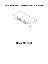
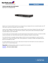
NetCommander B070-008-19

Tripp Lite NetCommander B070-008-19, B070-016-19 User manual

  • Hello! I am an AI chatbot trained to assist you with the Tripp Lite NetCommander B070-008-19 User manual. I’ve already reviewed the document and can help you find the information you need or explain it in simple terms. Just ask your questions, and providing more details will help me assist you more effectively!
WARRANTY
REGISTRATION
Register online today for a chance
to win a FREE Tripp Lite product!
www.tripplite.com/warranty
Owner’s Manual
Note: Follow these instructions and operating procedures to ensure correct performance and to prevent damage
to this unit or to its connected devices.
Copyright © 2010 Tripp Lite. All rights reserved. All trademarks are the property of their respective owners.
The policy of Tripp Lite is one of continuous improvement. Specifications are subject to change without notice.
NetCommander
Cat5 Rackmount
Console KVM Switches
Models #: B070-008-19 & B070-016-19
1111 W. 35th Street, Chicago, IL 60609 USA
www.tripplite.com/support
201002116 93-2925.indd 1 3/15/2010 11:48:40 AM
2
Table of Contents
Features.. ......................................................................................... p. 3
Package Includes….. ...................................................................... p. 3
Accessories… ................................................................................. p. 3
Configuration… .............................................................................. p. 4
Front View ............................................................................... p. 4
Rear View ................................................................................ p. 5
Installation…….. ............................................................................ p. 5
Pre-Installation Guidelines ...................................................... p. 5
Connecting the NetCommander KVM System….. ................ p. 5
NetCommander Server Interface Units ................................... p. 6
Connecting the Power Supply ................................................. p. 7
Resetting the KVM Switch ..................................................... p. 7
Rackmount Considerations ..................................................... p. 8
Rackmounting the NetCommander KVM ............................. p. 8
Cascading NetCommander KVM Switches............................ p. 9
Connecting the B050-000 or B051-000 ................................ p. 10
Operation ...................................................................................... p. 10
Basic Operation ..................................................................... p. 10
Keyboard Hotkeys ................................................................. p. 10
On-Screen Display ................................................................ p. 11
Navigating the OSD .............................................................. p. 11
Selecting a Computer ............................................................ p. 11
OSD Settings (F2) ................................................................. p. 11
General Settings .................................................................... p. 12
F7 Defaults ............................................................................ p. 14
Port Settings .......................................................................... p. 14
Time Settings......................................................................... p. 15
Security ................................................................................. p. 16
User Settings ......................................................................... p. 17
OSD Help Window (F1) ....................................................... p. 17
Scanning Computers (F4) ..................................................... p. 17
Tuning (F5) ........................................................................... p. 18
Moving the Label (F6) .......................................................... p. 18
Firmware Upgrade ........................................................................ p. 18
Firmware Upgrade System Requirements ............................ p. 18
Upgrading the KVM Firmware ............................................. p. 18
KVM Switch/SIU Reset ........................................................ p. 21
Troubleshooting ............................................................................ p. 22
USB/SUN Combo Keys ............................................................... p. 23
Specifications ................................................................................ p. 23
1-Year Limited Warranty/Warranty Registration .......................... p. 24
Español ....................................................................................... p. 25
Françis ....................................................................................... p. 51
201002116 93-2925.indd 2 3/15/2010 11:48:40 AM
3
Features
• 8-portor16-portKVMswitchwithbuilt-in19"LCDdisplay,keyboardandtouchpad
• Accessandcontrolmultiplemulti-platformcomputersfromasingleconsole
• Hot-swappable:disconnectandreconnectUSBcomputerswithoutrebooting
• Auto-scan:withvariabletimeinterval
• Compactdesign:1Urackmountable
• Easyportselectionusing(1)OnScreenDisplay(OSD),(2)keyboardhotkeys
key sequences
• Expandable:controlupto256computersbyaddingadditionalKVMswitches
• Simplecablemanagement:usestandardCat5epatchcord(maximumdistance100ft)to
connect to each computer
• Built-inmonitorsupportsresolutionsupto1280x1024
• Multi-platform:supportsPS/2andUSBcomputers/server
• CompatiblewithWindows
®
,Mac
®
,Linux,UNIXandDOS
• OptionalTrippLiteB050-000orB051-000IPRemoteAccessUnittoaccesstheKVMvia
LAN,WANortheInternet
Package Includes
• B070-008-19orB070-016-1919"Cat5ConsoleKVMSwitch
• C13to5-15PPowerCord
• RJ11toDB9FirmwareUpgradeCable
• RackmountHardware
• JumperCable(toconnecttheKVMconsoleportstotheintegratedconsoleports*)
*Theincludedjumpermustbeconnectedfortheunittofunction.
Accessories
• B072-008-1orB072-016-1Cat5RackmountKVMSwitch
• B078-101-PS2ServerInterfaceUnit;PS/2
• B078-101-USBServerInterfaceUnit;USB
• N001-SeriesSnaglessCat5ePatchCables
• N002-SeriesCat5ePatchCables
• N201-SeriesCat6SnaglessPatchCables
• B050-000orB051-000IPRemoteAccessUnit
201002116 93-2925.indd 3 3/15/2010 11:48:40 AM
4
1
2 3 4
5
6
7
8
9
10
11
12
13
Configuration
Figure 1 NetCommander KVM front panel
Front View
Figure 2 NetCommander KVM Buttons
Auto:WhentheLCDMenuisclosed,pressingtheAUTObuttonwillperformanAuto
Adjustonthemonitorscreen.WhentheLCDMenuisopen,pressingtheAUTObutton
will bring you back to the previous screen/selection. If the LCD Menu cannot go back
anyfurther,theAUTObuttonwillclosedownthemenu.
Menu:WhentheLCDMenuisclosed,pressingtheMENUbuttonwillopenit.When
theLCDMenuisopen,pressingtheMENUbuttonwillselectahighlightedoption.
On/Off Button: Pressing this button will turn the monitor screen on or off.
< :WhentheLCDMenuisopen,pressingthe<buttonwillmovethehighlightbartothe
left.Whenmodifyingaselectedoption,pressingthe<buttonwilldecreasetheoption.
> :WhentheLCDMenuisopen,pressingthe>buttonwillmovethehighlightbartothe
right.Whenmodifyingaselectedoption,pressingthe>buttonwillincreasetheoption.
Handle:Pulltoslidethemoduleout;pushtoslidethemodulein.
19" LCD Monitor:Afterslidingthemoduleout,flipupthecovertoaccesstheLCD
monitor,keyboardandtouchpad.
Keyboard
Slide Release: Mechanism to lock the drawer closed when the console is not in use.
Preventsitfromaccidentallyslidingopen.Toslidetheconsoleout,youmustfirstrelease
it by moving the tab sideways.
Rackmounting Brackets: There are rackmount brackets to secure the chassis to a
system rack located at each corner of the unit.
2-Button Touch Pad: Leftbuttonisleftclick,rightisrightclick.
LCD Display Controls: The LCD OSD controls located here control the position and
picture settings of the LCD display. See LCD OSD configuration for details.
Railway Release Tabs:Whenthedraweriscompletelypulledouttotheend,therailway
system will lock. Push the release tabs on both sides to release the drawer so that it can
be pushed back in.
1
2
3
4
5
6
7
8
9
10
11
12
13
201002116 93-2925.indd 4 3/15/2010 11:48:41 AM
5
1 2
3
4
5
6
Figure 3 NetCommander KVM rear panel
Rear View
Configuration (continued)
Power Socket: The power cord plugs in here from the AC power source.
On/Off Switch: Turns the KVM Switch on and off.
Firmware Upgrade Port: Plug included firmware upgrade cable into this port to down-
load firmware upgrade data.
CPU Port Section: Plug the Cat5e cables from each PC or server into these ports.
KVM Console Ports*
Integrated Console Ports*
*TheKVMcomeswithaJumperCabletoconnecttheIntegratedConsolePortstotheKVMConsolePorts.This
cablemustbeconnectedfortheunittofunction.DonotremovetheJumperCableunlessyouareinstallingaTripp
Lite B050-000 or B051-000 IP Remote Access Unit. See the IP Remote Access Unit connection
instructions on page 10 for details.
1
2
3
4
5
6
Installation
• Switchoffallcomputers*
• TheKVMcomeswithaJumperCabletoconnecttheIntegratedConsolePortsto
the KVM Console Ports. This cable must be connected for the unit to function. Do not
removetheJumperCableunlessyouareinstallingaTrippLiteB050-000orB051-000IP
Remote Access Unit. See the IP Remote Access Unit connection instructions on page 10
for details.
• Ensurethatthecablesarenotclosetoanysourcesofelectricalnoiseinterferencesuchas
fluorescentlights,HVACsystemsormotors
• EnsurethatthedistancebetweenanycomputerandtheKVMswitchdoesnotexceed100ft.
*PS/2computersneedtohavetheKeyboardandMouseconnectorsinstalledbeforetheyareturnedon.Ifyouplugthe
KeyboardandMouseconnectorsintoanactivePS/2computer,itmaynotrecognizethem,causingthemnottowork.
Pre-Installation Guidelines
Connecting the NetCommander KVM System
ConnecteachcomputertotheKVMswitchusingaTrippLiteB078-101-PS2*or
B078-101-USB*ServerInterfaceUnit(SIU)andaCat5epatchcable.
*Cat5cableshouldbenolongerthan100ft..
201002116 93-2925.indd 5 3/15/2010 11:48:41 AM
Up to 100 ft
6
NetCommander Server Interface Unit (SIU)
The NetCommander Server Interface Unit
The Server Interface Unit gets its power from the connected computer. In the case of the
NetCommanderPS/2ServerInterfaceUnit(B078-101-PS2),thepowerisdrawnfromthe
keyboard port. In the case of the NetCommander USB Server Interface Unit (B078-101-
USB),thepowerisdrawnfromtheUSBport.Whenconnectedandreceivingpower,the
greenLEDontheSIUwillilluminate.WhenconnectedtotheactiveportontheKVM,the
orange LED will illuminate.
Connecting a NetCommander PS/2 Server Interface Unit (Model # B078-101-PS2)
1. Shut down the computer being connected to the B078-101-PS2 (SIU)
2. Connect the B078-101-PS2 VGA connector to the computers VGA port
3. Connect the B078-101-PS2 PS/2 Keyboard connector to the computers PS/2 Keyboard port
4. Connect the B078-101-PS2 PS/2 Mouse connector to the computers PS/2 Mouse port
5.ConnectoneendoftheCat5patchcabletotheRJ45portontheB078-101-PS2*
6.ConnecttheotherendoftheCat5patchcabletothedesiredRJ45portonthe
ConsoleKVM.*ThegreenLEDwillilluminatewhenconnectedandreceivingpower.
7. Repeat these steps for each additional PS/2 computer/server you are connecting to the
Console KVM
Installation (continued)
Figure 4 NetCommander PS/2 Server Interface Unit
SIU = Server Interface Unit
201002116 93-2925.indd 6 3/15/2010 11:48:42 AM
7
Up to 100 ft
Figure 5 NetCommander USB Server Interface Unit
Installation (continued)
SIU = Server Interface Unit
Connecting a NetCommander USB Server Interface Unit (Model # B078-101-USB)
1. Connect the B078-101-USB VGA connector to the computers VGA port
2. Connect the B078-101-USB USB connector to the computers USB port
3.ConnectoneendoftheCat5patchcabletotheRJ45portontheB078-101-USB*
4.ConnecttheotherendoftheCat5patchcabletothedesiredRJ45portonthe
ConsoleKVM.*ThegreenLEDwillilluminatewhentheSIUisconnected
and receiving power.
5. Repeat these steps for each additional USB computer/server you are connecting to the
Console KVM
*Cat5cableshouldbenolongerthan100ft.
1. Plug in the KVM using only the power cord supplied with the unit.
2. Switch ON the Console KVM.
ToresettheKVMswitch,turntheunitoffandthenbackonusingthepowerswitchonthe
back. The Server Interface Units are unaffected by this reset.
Connecting the Power Supply
Resetting the KVM Switch
201002116 93-2925.indd 7 3/15/2010 11:48:42 AM
1
2
1
2
8
Installation (continued)
Rackmount Considerations
Rackmounting the NetCommander KVM
The NetCommander Console KVM is designed for mounting in a 1U rack system. For con-
venience,arackmountingkitisincludedforquickinstallation.Thevariousmounting
optionsareexplainedinthesectionsthatfollow.
Ambient Operating Temperature
The ambient operating temperature in the rack may be an issue and is dependent upon the
rackloadandventilation.Wheninstallinginaclosedormulti-unitrackassembly,makesure
thatthetemperaturewillnotexceedthemaximumratedambienttemperature.(32ºto104ºF)
Airflow
Ensure that the airflow within the rack is not compromised.
Circuit Overloading
Whenconnectingtheequipmenttothesupplycircuit,considertheeffectthatoverloadingof
circuits might have on over-current protection and supply wiring.
Reliable grounding of rack-mounted equipment should be maintained.
To protect against circuit overloading you should connect your B070-016-19 Console KVM
and attached computers/servers to a Tripp Lite SmartPro
®
or SmartOnline
®
UPS System.
2-Post Rackmounting
The Console KVM can also be mounted in a 2-post rack installation using the optional
2-Post Rackmount Kit (model #: B019-000). The mounting hardware allows for the console
to be opened with the drawer in any position. Heavy-duty 14-gauge steel provides stability
and prevents the console frame from twisting. See the B019-000 instructional manual for
detailed mounting instructions.
Standard Rackmounting
The standard rackmounting brackets that come attached to the
console allow the unit to be installed in standard 1U racks
by a single individual.
Slide out the rear mounting brackets from the console
and mount both brackets (separate from the console) to the
inside rear of a standard 1U rack system using user-supplied
screws.
Take the console and gently slide it into the two rear-
mounted brackets in the rack and secure the console in place
by inserting user-supplied screws.
201002116 93-2925.indd 8 3/15/2010 11:48:43 AM
Model: B070-016-19
Model: B072-008-1
or B072-016-1
Model: B072-008-1
or B072-016-1
9
Installation (continued)
TocascadetwoormoreNetCommanderKVMswitches,followtheinstructionsbelow.
Connectupto256computers*usinganycombinationofB072-008-1andB072-016-1KVM
switches.Youcanonlycascade1extralevelofKVMswitchesontotheConsoleKVM.
*Whenall16portsofaB070-016-19haveaB072-016-1cascadedfromthem.
SettingthedifferentOSDdisplayhotkeysforcascadedKVMsisexplainedonpage14.
Figure 6 Cascading NetCommander KVM switches
Cascading NetCommander KVM Switches
SIU = Server Interface Unit
201002116 93-2925.indd 9 3/15/2010 11:48:46 AM
10
Switch between the connected computers using any of the following methods:
• TheOSD(OnScreenDisplay)
• Keyboardhotkeycommands
The OSD is also used to adjust various settings.
A confirmation label at the top of your monitor screen identifies which computer is currently
selected.
Toswitchtothenextcomputer,pressandreleasethe[Shift]key,thenpressthe[+]key.
Toswitchtothepreviouscomputer,pressandreleasethe[Shift]key,thenpressthe[-]key.
Note! You can use the [+] key of the alphanumeric section or of the numeric keypad on
a US English keyboard. With a Non-US English keyboard, use the [+] key of the
numeric keypad only.
Installation (continued)
Basic Operation
Keyboard Hotkeys
Operation
Connecting a B050-000 or B051-000 IP Remote Access Unit to the B070-016-19
1.DisconnecttheJumperCableConsoleConnectorsthatarepluggedintotheKVM
Console Ports.
2.PlugtheendoftheJumperCableyoujustdisconnectedintotheLocalConsolePortsof
the IP Remote Access Unit.
3. Plug the PS/2 and VGA connectors from the IP Remote Access Unit into the KVM
Console Ports.
4. For further setup instructions for the B050-000 or B051-000 IP Remote Access Unit refer
to the Owner's Manual that comes with the unit.
Figure 7 Connecting a B050-000 or B051-000 IP Remote Access Unit
201002116 93-2925.indd 10 3/15/2010 11:48:46 AM
11
Operation (continued)
Figure 8 The OSD Main Window
Navigating the OSD
Tomoveupanddown,usethe[ ] and [ ] arrow keys.
Tojumpfromonecolumntothenext(whenrelevant),usethe[Tab] key.
ToexittheOSDortoreturntothepreviousOSDwindow,press[Esc].
Selecting a Computer
To select a computer:
1. Move to the desired computer line.
2. Press the Enter key. The selected computer will be accessed and the OSD screen will close.
Note: While the OSD Screen is active the Keyboard Hotkey Commands and Mouse will be
deactivated.
On-Screen Display
To invoke the OSD:
PressandreleasetheShiftkeytwicetoopentheOSDMainMenu.LineswithBluetext
representportsthathaveacomputer/serverconnectedtothem,whichiscurrentlyturnedon.
LineswithGraytextrepresentportsthateitherhasacomputer/serverconnectedtothem,
whichisturnedoff;ortheyhavenocomputer/serverconnectedatall.TheTypecolumn
indicates whether a computer/server (C) is connected to the port or a KVM Switch (S) is
connectedtotheport.FortheTypecolumntodisplayS,theusermustchangetheHotkey
setting for the cascaded KVM. (See page 14 for details.)
OSD Settings (F2)
Press [F2] to open the OSD Settings window (see Figure 9).
Figure 9 The Settings Window
Note:IftheOSDispasswordprotected,onlytheAdministratorwillbeabletogetaccessto
the F2 settings window by using the appropriate password.
201002116 93-2925.indd 11 3/15/2010 11:48:47 AM
12
Operation (continued)
General Settings
WiththehighlightlineonthewordGENERAL,press[Enter]. The General Settings window
appears (see Figure 10).
Figure 10 The General Settings window
Security
The Security option in the OSD General Settings Menu allows you to activate or deactivate
PasswordSecurity.Bydefault,PasswordSecurityissettoOff.OnlytheAdministratorwill
be able to activate/deactivate Password Security.
To activate/deactivate Password Security:
1. Highlight the Security option in the OSD General Settings Menu
2. Press the space bar to change Password Security On/Off
3. Pressing the space bar will display a prompt requiring you to enter the Security Password.
(Security Password defaults as 'Admin')
4.Onceyou'vetypedinthecorrectpasswordandhitenter,thePasswordSecuritystatuswill
be changed
Note:OncePasswordSecurityisactivated,HotkeyCommandswillbedeactivated,leaving
you limited to the OSD Menu as your only way to select a port. Once you leave the OSD
Menu,youwillneedtohitthe'Shift,Shift'commandtoaccesstheOSDMenuandselect
another port. You will be required to enter your password each time you enter the OSD Menu.
*Seepage16-17formoreinformationontheSecurityfeatures.
Changing the OSD Hotkey
By default the primary Hotkey is the Shift key. You have the ability to replace the Shift key
with one of 4 different choices in the OSD General Settings Menu.
(SH-SH):ThisrepresentstheShiftkey.ToaccesstheOSDMenuyouhit'Shift,Shift.'To
accessthenextKVMinlinehit'Shift,+.'ToaccessthepreviousKVMinlinehit'Shift,-.'
(CL-CL): This represents the Ctrl key. To access the OSD Menu you can either hit the Left
Ctrl key 2 times or you can hit the Right Ctrl key once and then the Left Ctrl key. You can hit
eitherCtrlkeyonceandthe+keytoaccessthenextKVMinline.YoucanhiteitherCtrlkey
once and the - key to access the previous KVM in line.
(CLF11): This represents the Ctrl key and the F11 key. To access the OSD Menu you hit
eitherCtrlkeyandthenF11.YoucanhiteitherCtrlkeyonceandthe+keytoaccessthe
nextKVMinline.YoucanhiteitherCtrlkeyonceandthe-keytoaccessthepreviousKVM
in line.
(PRSCR): This represents the Print Screen key. To access the OSD Menu you hit the Print
Screenkeyonce.WhenyouselectPrintScreenasyourhotkey,theportselectionhotkeycommands
aredeactivated,leavingtheOSDMainMenuastheonlywaytoswitchtoanotherport.
201002116 93-2925.indd 12 3/15/2010 11:48:47 AM
13
Operation (continued)
WhenyouhavecascadedKVMswitches,alowerlevelSwitchmusthaveadifferentOSD
display hotkey than a higher level switch.
To change the top-level switch hotkey:
1. Highlight the Hotkey option in the OSD General Settings Menu
2. Press the space bar to toggle through the various options
3.Whenyou'veselectedthedesiredhotkey,simplyexittheOSD.HittingtheEnterkeyis
not required to activate your selection
To change a lower level hotkey:
1. Connect a keyboard and monitor to the lower level switch
2.HitShift,ShifttoopentheOSDMenu
3.HitF2togettotheGeneralSettingsMenu,andhighlighttheHotkeyoption
4. Press the Space Bar to toggle through the various hotkeys
5.Whenyou'veselectedthedesiredhotkey,simplyexittheOSDMenu.HittingtheEnter
key is not required to activate your selection
6. Follow the instructions on page 14 to update the Port Settings menu in the top-level
KVMs OSD to reflect the lower-level KVMs new hotkey
Note:WhenPasswordSecurityisactivated,allportselectionhotkeycommandsare
deactivated,leavingtheOSDMainMenuastheonlywaytoswitchtoanotherport.
Auto Skip
The Auto Skip option allows you to choose whether you want Inactive ports to be selectable
ornot.IftheAutoSkipoptionisturnedon,InactiveportswillnotbeaccessibleviatheOSD
MainMenuorthePortSelectionHotkeyCommands.IftheAutoSkipoptionisturnedon,
you will be able to access Inactive ports using either the OSD Main Menu or the Port
Selection Hotkey Commands.
To change the Auto Skip setting:
1. Highlight the Auto Skip option in the OSD General Settings Menu
2. Press the space bar to turn the Auto Skip option On/Off
Serial Port
The Serial port is used for the Firmware upgrade. Serial port On means the program can be used.
To change the Serial port setting:
1. Highlight the Serial Port option in the OSD General Settings Menu.
2. Press the space bar to turn the Serial Port option On/Off.
Changing the Keyboard Language
The keyboard is preset to US English. It can be changed to French (FR) or German (DE) by
doing the following:
1. Highlight the Keyboard language option in the OSD General Settings Menu
2. Press the space bar to toggle through the various options.
3.Whenyou'veselectedthedesiredlanguage,simplyexittheOSD.HittingtheEnterkey
is not required to activate your selection
201002116 93-2925.indd 13 3/15/2010 11:48:47 AM
14
Reset OSD General Settings Menu to Defaults (F7)
WhenintheOSDGeneralSettingsMenu,youcanresetalloftheoptionstotheoriginal
defaultsettings,erasinganychangesyouhavemade.IfyouhavechangedtheSecurity
Passwords,theywillberesettotheirdefaultsaswell.
Operation (continued)
Ports Settings
IntheOSDSettingsMenu(AccessbypressingF2intheOSDMainMenu),highlightthe
Ports option and press enter.
Figure 11 Ports Settings window
Editing the Computer Name
Bydefaulteachportisnamed'Computer01,Computer02,etc.'Topersonalizethesenames
foreachcomputer,highlightthedesiredportandtypedirectlyoverthetextthat'salready
there.Eachnamehasamaximumof15characters,eachspacecountingasonecharacter.To
deleteacharacter,simplyhighlightitandpressthespacebar.
Editing the Keyboard (KB) Column
TheKVMoperateswithWindows,Linux,HPUX,AlphaUNIX,SGI,DOS,Novell,MAC,
USB or Open VMS. By default the Keyboard Mode is set to PS for Intel Based computers.
Foradifferentkeyboardmode,highlightthedesiredportandpresstheTabkeytohighlight
the KB column. Press the space bar to toggle through the following options:
U1-HPUX
U2-AlphaUNIX,SGIorOpenVMS
U3-IBMAIX
Adding/Changing a Hotkey (HKEY) for Cascaded KVM Switches
WhenaKVMSwitchiscascadedtotheConsoleKVM,itisnecessarytoselectahotkeyin
this field. This is required so the top-level KVM knows that when the Cascaded KVM Port is
selectedandyouhittheselectedOSDHotkeyCommand,itissupposedtopulluptheOSD
MainMenuforthatKVMswitch.IfaHotkeyisnotselectedforacascadedKVM,youwill
not be able to access the cascaded KVMs OSD. For connected computers/servers this field
should have “NO” selected.
Editing the Switch Name
TheKVMSwitchNameappearsatthebottomoftheOSDGeneralSettingsMenu,andcan
bechangedtowhateveryouwant.Whencascading,itisnecessarytoaccessthecascaded
KVMs OSD using it's own hotkey. Giving cascaded KVMs OSDs unique names makes it
easier when accessing them to verify which switches OSD you are accessing. To change this
namesimplytypeovertheexistingletters.Youcancreateanameupto18charactersin
length,withspacescountingascharacters.
201002116 93-2925.indd 14 3/15/2010 11:48:47 AM
15
Operation (continued)
Time Settings
In the Settings window navigate to the Time line and press [Enter]. The Time settings
window appears (see Figure 12).
Figure 12 Time settings window
SCN - Sets the amount of time spent on the selected computer when Auto Scanning.
LBL - Sets the amount of time the OSD label that shows which computer is currently
accessed is displayed.
T/O - Whenpasswordprotectionisactivated,youcanautomaticallydisabletheKeyboard,
MouseandMonitorafterasetamountofinactivetime,requiringapasswordtobeenteredto
regainaccesstotheKVMswitch.WhenTimedOut,pressthe'Shift,Shift'OSDHotkey
Commandtopullupthepasswordprompt,whichwilltakeyoubacktotheOSDMainMenu
once you enter your password.
To set the above periods:
1. On the desired line press Tab to jump to the desired column.
2.Placethecursoroveroneofthe3digitsandtypeanewnumber.Enteraleadingzero
wherenecessary.Forexample,type030for30seconds.
Enter 999 in the LBL column to have the label displayed continuously. Enter 000 if you
do not want the label to appear.
Enter 999 in the T/O column to disable the Timeout function.
Enter000ifyouwanttheTimeoutfunctiontoworkimmediately.*
*ThiswillliterallycausetheTimeoutfunctiontobeginimmediatelywhenthecomputerportisselected.This
willessentiallyfreezeaccesstotheKVM,notallowingtheuserenoughtimetohittheOSDHotkeyCommandto
pull up the password prompt. It is recommended that you always keep the T/O set to 5 seconds or higher. If you
settheT/Oat000andgetlockedoutoftheKVM,turntheConsoleKVMOffandthenbackOn.
ThiswillresettheKVM,leavingablankscreenonthemonitor.Hitthe'Shift,Shift'OSDHotkeyCommandto
pullupthepasswordprompt.Onceyoutypeinyourpassword,youwillagainhaveaccesstotheOSDMainMenu.
Enter 999 in the SCN column to display the screen for 999 seconds.
Enter 000 to skip the computer screen.
To add/change a hotkey:
1. Highlight the desired port and press the Tab key until the HKEY column is highlighted
2. Press the space bar to toggle through the various choices
3.Whenyou'veselectedthedesiredhotkey,simplyexittheOSD.HittingtheEnterkeyisnot
required to activate your selection
201002116 93-2925.indd 15 3/15/2010 11:48:47 AM
16
Operation (continued)
Security
Figure 13 The Security settings window
The OSD offers an advanced password security system made up of three different security
levels,eachhavingitsownaccessrights.
Administrator (Status A):TheAdministratorhasaccesstoallfeaturesoftheKVM,allow-
ingthemtoSet/ModifyallPasswordsandSecurityProfiles,gainfullaccesstoanycomputer
connected to the KVM and usage of all OSD features.
Supervisor (Status S): The supervisor has full access to all computers connected to the
KVMandcanusetheAutoScan(F4),Tuning(F5)andConfirmationLabelMoving(F6)
functions in the OSD. The Supervisor can not change any of the OSD Settings or Security
Settings.
User (Status U): There can be up to 6 Users set up by the Administrator for access to the
KVM. Users are able to use the OSD Main Menu to access a connected computer and can
usetheAutoScan(F4),Tuning(F5)andConfirmationLabelMoving(F6)functionsinthe
OSD. Users do not have the ability to use any other OSD features. The Administrator will
choose which computers they have access to and which they do not. There are 3 types of
access the Administrator can give a User:
Y - This gives the user full access to a connected computer.
V - This gives the user view only access to a computer. Keyboard and mouse functionality
are not available.
N - This means a user is not allowed to access a connected computer. If the User attempts
toaccessacomputertheyarenotallowedto,ablankscreenwillappear.
WhenPasswordSecurityissettoon,onlytheadministratorcanchangethe
Security Settings of the KVM switch.
Security Settings
1. Highlight the Security option in the OSD Settings Menu and hit the Enter key.
2.TochangethenameoftheAdministrator,SupervisororUser,highlightthedesiredname
and simply type over what's already there. Any letters left over can be deleted by pressing
the space bar.
3.Tochangethepassword,hittheTabkeytohighlightthePasswordcolumnofthedesired
person and type in the new password.
4.Thelastcolumn(T)referstothelevelofaccess;Administrator(A),Supervisor(S)orUser
(U).Youcanchangetheseifyouwant,buttherecanonlybe1Administrator,1Supervisor
and 6 Users.
Security Settings
201002116 93-2925.indd 16 3/15/2010 11:48:48 AM
17
OSD HELP Window (F1)
To access the HELP window press [F1]. The HELP window is displayed (see Figure 15).
Figure 15 The HELP window
Please note! All the functions in the Help window are performed from the OSD Main
Menu. The Help window only serves as a reminder of the OSD function keys.
User Settings
1. Highlight the Users option in the OSD Settings Menu and hit the Enter key.
2. The Users will be represented in the 6 columns on the right side of the screen. To change
theaccessforagivencomputer,highlightthedesiredcomputerandhittheTabkeyuntil
the desired user is highlighted.
3.Pressthespacebartotogglebetweenthe3accessoptions(Y,VorN).Seepage16for
details on these 3 options.
Operation (continued)
The amount of time spent on a computer when Auto Scanning is adjustable. See page 15 for
details.
To activate scanning:
1. Press the [Shift] key twice to activate the OSD.
2. Press the [F4] key.
Each active computer will be displayed in sequence. A Scan label appears in the top left corner.
To deactivate scanning:
Press [F4].
Scanning Computers (F4)
Figure 14 The Users Settings Window
201002116 93-2925.indd 17 3/15/2010 11:48:48 AM
18
Operation (continued)
Moving the Label (F6)
You can position the OSD label anywhere on the screen.
To position the label from the Main window:
1. Move to the desired computer using the Up and Down Arrow keys.
2. Press the [F6] key. The selected screen image and Identification label are displayed.
3. Use the arrow keys to move the label to the desired position.
4. Press [Esc]tosaveandexit.
The NetCommander KVM Firmware Upgrade Utility allows you to upgrade both the KVM
and Server Interface Units (SIUs). Each KVM in a cascade installation must be upgraded
individually.WhendoneupgradingthefirstKVMintheinstallation,performtheupgrade
procedureoneachsubsequentKVM.Toupgradeyourfirmware,followthestepsbelow:
1. Make sure that the Serial Port setting in the OSD General Settings menu is set to On.
This makes the serial port on the back of the KVM switch available for use in a firm-
ware upgrade.
2.UsingtheincludedRJ11toDB9firmwareupgradecable,connecttheupgradeporton
the back of the unit to an available serial port on a computer that is not connected to the
KVM.
Upgrading the KVM Firmware
Firmware Upgrade System Requirements:
• Windows2000orhigheroperatingsystem
• Pentium166orhigherwith16MBRAMand10MBfreeharddrivespace
• AvailableDB9serialport
Firmware Upgrade
Tuning (F5)
You can tune the image of any remote computer screen.
To adjust the screen image:
1. In the OSD Main Menu highlight the computer you want to adjust.
2. Press the [F5]key.Thescreenimageoftheselectedcomputerisdisplayed,alongwith
the Image Tuning label.
3. Adjust the image by using the Right and Left Arrow keys.
4.Whentheimageissatisfactory,press[Esc].
Note! Distance affects picture quality. The further away a remote computer is from the
KVM, the lower the image quality and the more tuning needed. Therefore put any
higher resolution computers closer to the KVM.
201002116 93-2925.indd 18 3/15/2010 11:48:48 AM
19
Firmware Upgrade (continued)
3. On the upgrade computer (the computer connected to the KVM via the firmware
upgradecable),gototheTrippLitewebsiteanddownloadtheNetCommanderFirmware
UpgradeUtility.exefile,FirmwareUpgrade.tfpfileandFirmwareUpgradeinformation
doc.
Note: The firmware upgrade information document will list the latest firmware for all
Tripp Lite NetCommander KVM switches and SIUs, which you will need to reference
when determining if your device has the latest firmware. The .tfp firmware upgrade file
contains firmware for both the KVM and SIUs.
4.RuntheNetCommanderFirmwareUpgradeUtility.exefile,andfollowtheinstructions
to install the utility on the upgrade computer.
1.Onceinstalledontheupgradecomputer,opentheNetCommanderFirmwareUpgrade
Utility.
201002116 93-2925.indd 19 3/15/2010 11:48:48 AM
20
Firmware Upgrade (continued)
1.CheckthefirmwareversionsoftheKVM(SwitchManager),KVMOSD(SwitchOSD)
andSIUsbyclickingontheboxesnexttothemandpressingtheF/W Version button.
Note: To select a device, you must first unselect any boxes that have already been
checked. To select or unselect all SIUs at once, simply click on the Select All or Unselect
All button at the bottom of the upgrade utility.
2. Compare the firmware versions of your devices to that of the firmware version listed in
the document from the Tripp Lite website. If your version is the same or newer than that
foundontheTrippLitewebsite,youdonotneedtoupgradeyourfirmware.Ifyour
versionisolder,proceedtothenextstep.
3. ClickontheboxnexttotheKVMOSD(SwitchOSD),KVM(SwitchManager)orSIU(s).
4. In the Filemenuatthetopoftheupgradeutilityscreen,selecttheOpen option and
navigate to the .tfp firmware upgrade file you downloaded from the Tripp Lite website.
5. In the Optionsmenuatthetopoftheupgradeutilityscreen,selecttheCom Portoption,
and choose the Com Port of the upgrade computer that the firmware upgrade cable is
connected to.
6. Click on the Start button at the bottom of the upgrade utility to begin the upgrade. A
prompt will appear to warn you that the KVM screen will be dark during the upgrade
process. Click on the OK button to proceed with the upgrade.
201002116 93-2925.indd 20 3/15/2010 11:48:49 AM
/