Page is loading ...

PAGE 1
FOR SERVICE TECHNICIAN’S USE ONLY
DO NOT REMOVE OR DESTROY
IMPORTANT SAFETY NOTICE — “For Technicians only”
This service data sheet is intended for use by persons having electrical, electronic, and
mechanical experience and knowledge at a level generally considered acceptable in the
appliance repair trade. Any attempt to repair a major appliance may result in personal injury
and property damage. The manufacturer or seller cannot be responsible, nor assume any
liability for injury or damage of any kind arising from the use of this data sheet.
Diagnostic Guide .................................................. 2
Activating Service Diagnostic Test Modes ............. 2
Diagnostic Test Modes ..................................... 3–5
Customer Viewable Fault Codes ............................ 5
Service Fault / Error Codes ............................... 6, 7
Automatic Tests ................................................... 8
Contents
Manual Tests ........................................................ 9
Troubleshooting Guide .................................. 10, 11
Troubleshooting Tests................................... 12–18
Main Control Connectors & Pinouts .................... 12
Component Locations & Washer Specs .............. 19
Wiring Diagrams .......................................... 20, 21
PART NO. W10280489D
IMPORTANT: Electrostatic Discharge (ESD) Sensitive Electronics
ESD problems are present everywhere. Most people begin to feel an ESD discharge at
approximately 3000V. It takes as little as 10V to destroy, damage, or weaken the main control
assembly. The new main control assembly may appear to work well after repair is finished,
but a malfunction may occur at a later date due to ESD stress.
Use an anti-static wrist strap. Connect wrist strap to green ground connection point or
unpainted metal in the appliance
-OR-
Touch your finger repeatedly to a green ground connection point or unpainted metal
in the appliance.
Before removing the part from its package, touch the anti-static bag to a green ground
connection point or unpainted metal in the appliance.
Avoid touching electronic parts or terminal contacts; handle electronic control assembly
by edges only.
When repackaging main control assembly in anti-static bag, observe above instructions.
Voltage Measurement Safety Information
When performing live voltage measurements, you must do the following:
Verify the controls are in the off position so that the appliance does not start when energized.
Allow enough space to perform the voltage measurements without obstructions.
Keep other people a safe distance away from the appliance to prevent potential injury.
Always use the proper testing equipment.
After voltage measurements, always disconnect power before servicing.

PAGE 2
FOR SERVICE TECHNICIAN’S USE ONLY
DO NOT REMOVE OR DESTROY
ACTIVATING THE SERVICE
DIAGNOSTIC TEST MODES
1. Be sure the washer is in standby mode
(plugged in with all indicators off).
2. Perform the following sequence of
movement using the cycle selector knob.
NOTE: AFTER RESET, sequence “a” through
“e” must be completed within 6 seconds.
RESET - Rotate cycle selector knob
counterclockwise one or more clicks
to clear sequence.
a. Rotate cycle selector knob clockwise
one click and wait ½ second.
b. Rotate cycle selector knob clockwise
one click and wait ½ second.
c. Rotate cycle selector knob clockwise
one click and wait ½ second.
d. Rotate cycle selector knob
counterclockwise one click and
wait ½ second.
e. Rotate cycle selector knob
clockwise one click.
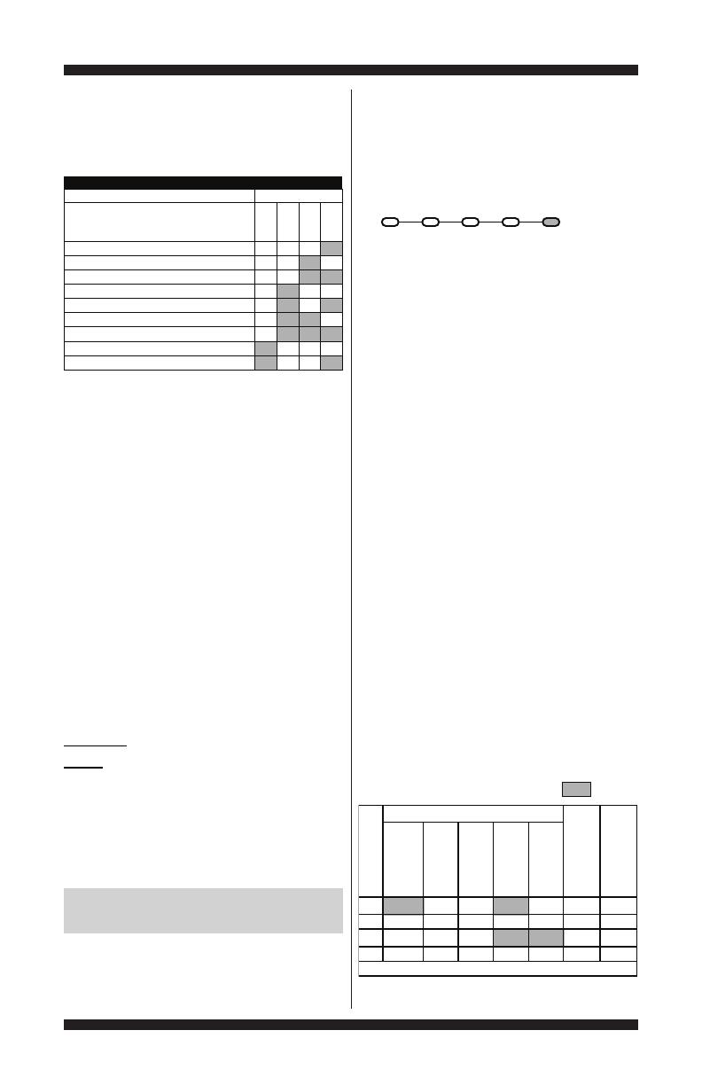
Successful activation of Diagnostic Test
Modes will be indicated by all status
LEDs (except for Lid Locked) flashing
ON and OFF in half-second intervals.
NOTE: LED names may vary between
makes and models.
Legend: = ON = OFF
Figure 2 - Status LEDs flashing ON and OFF
If the status LEDs do not display as
described above, the sequence may
not have been completed within 6
seconds. Repeat step 2 to ensure this
was not the cause. If still unsuccessful,
see Unsuccessful Entry, page 3.
Fill Wash Rinse Spin Done
0.5 Seconds ON
0.5 Seconds OFF
R
L
L
R
R
R
DIAGNOSTIC GUIDE
Before servicing, check the following:
Make sure there is power at the wall outlet.
Has a household fuse blown or circuit breaker
tripped? Was a regular fuse used? Inform
customer that a time-delay fuse is required.
Are both hot and cold water faucets open
and water supply hoses unobstructed?
All tests/checks should be made with a
VOM (volt-ohm-milliammeter) or DVM
(digital-voltmeter) having a sensitivity of
20,000 Ω per volt DC or greater.
Resistance checks must be made with
washer unplugged or power disconnected.
IMPORTANT: Avoid using large
diameter probes when checking harness
connectors as the probes may damage
the connectors upon insertion.
Check all harnesses and connections before
replacing components. Look for connectors
not fully seated, broken or loose wires and
terminals, or wires not pressed into connectors
far enough to engage metal barbs.
A potential cause of a control not
functioning is corrosion or contamination on
connections. Use an ohmmeter to check for
continuity across suspected connections.
DIAGNOSTIC LED – MAIN CONTROL
A troubleshooting tool has been implemented
onto the main control board—a diagnostic LED.
LED ON – The Control is detecting correct incoming
line voltage and the processor is functioning.
LED OFF – Control malfunction. Perform TEST #1:
Main Control, page 12, to verify main control
functionality.
SERVICE DIAGNOSTIC TEST MODES
These tests allow factory or service personnel
to test and verify all inputs to the main control
board. You may want to do a quick and overall
checkup of the washer with these tests before
going to specific troubleshooting tests.
LED Location
Figure 1
PAGE 3
FOR SERVICE TECHNICIAN’S USE ONLY
DO NOT REMOVE OR DESTROY
FAULT CODE DISPLAY MODE (Pgs 6–7)
To access fault/error codes, perform steps 1
and 2 of Activating the Service Diagnostic Test
Modes. Turn the cycle selector knob until the
status LEDs correspond as follows:
“Done” LED On
Press the START button to enter Fault Code
Display Mode. The status LEDs flash on and off.
1. To view last 4 fault codes:
Turn cycle selector knob clockwise to view
fault codes in the order of most recent to
oldest. (Refer to Fault/Error Code charts
on pages 6 & 7.)
NOTE: A fault/error code will be removed
from memory if it does not reoccur after
10 consecutive wash cycles.
2. To clear fault codes:
Turn cycle selector knob until the status LEDs
flash ON and OFF (see figure 2, page 2).
Press and hold the START button
for 3 seconds to clear all fault codes
and exit Fault Code Display Mode.
Fault/Error Code Display Method
Fault/error codes are displayed by alternating the
state of the Status LEDs in one second intervals.
All fault/error codes have an F# and an E#. The
F# indicates the suspect System/Category and
the E# indicates the suspect Component system.
If the Fill or Sensing LED is ON, the Fault
Number is represented; if OFF, the Error Number
is represented (see example below). The
remaining LEDs (Wash, Rinse, Spin, and Done)
represent the fault and error code in binary. (See
Fault/Error Code Charts on pages 6 & 7 for more
information.) = ON.
LED names may vary between makes and models.
3. There are several accessible Diagnostic
Test Modes shown in the chart below. To
select the desired Mode of Operation, turn
the cycle selector knob until the status LEDs
match the mode desired to enter.
4. Press the START button to enter desired
mode of operation.
Refer to the following pages for detailed
information on each mode of operation:
FAULT CODE DISPLAY MODE: Page 3
AUTOMATIC TEST MODE: Page 4
MANUAL TEST MODE: Page 4
CALIBRATION MODE: Page 4
SALES DEMO MODE: NOT FOR SERVICE USE*
UI TEST MODE: Page 4
SW VERSION DISPLAY MODE: Page 5
FACTORY DIAGNOSTICS: If accessed, washer
must be recalibrated (see Calibration Mode)
TACHOMETER VERIFICATION MODE: Page 5
*Press and hold the START key for 3 seconds to exit.
Unsuccessful Entry
If entry into diagnostic test mode is unsuccessful,
refer to the following indication and action:
Indication: None of the LEDs turn on.
Action: Press START button to enter setting mode.
If indicators come on, repeat steps 1
through 4 of Activating the Service
Diagnostic Modes. NOTE: Rotating the
dial too fast or too slow will affect entry.
If no indicators come on after pressing the
START button, go to TEST #1, page 12.
EXITING THE SERVICE
DIAGNOSTIC TEST MODES
Press and hold the START button for 3 seconds
at any time to exit diagnostic test modes.
Washer will exit diagnostic test modes after 5
minutes of inactivity or unplugging the power cord.
EDOM
WASH
RINSE
SPIN
DONE
Fault Code Display Mode
1
Automatic Test Mode
2
Manual Test Mode
2
Calibration Mode
4
Sales Demo Mode
4
UI Test Mode
4
STATUS LEDs
DIAGNOSTIC TEST MODES
SW Version Display Mode
41
Factory Diagnostics Mode
Tachometer Verification Mode
18
8
(Status LED names may vary
between makes and models)
1
1
2
2
Fill Wash Rinse Spin Done
1F 8421F2
0.5
20
.5
3E 8421E3
0.5
41
.0
Repeat…
STATUS LEDs
Frame Number
FILL
SENSING
WASH
RINSE
SPIN
DONE
Fault / Error Code
Frame Timing (sec.)

PAGE 4
FOR SERVICE TECHNICIAN’S USE ONLY
DO NOT REMOVE OR DESTROY
AUTOMATIC TEST MODE (Page 8)
To access Automatic Test Mode, perform steps
1 and 2 of Activating the Service Diagnostic
Test Modes. Turn the cycle selector knob until
the status LEDs correspond as follows:
“Spin” LED On
NOTE: Status LED names may vary between
makes and models.
Press the START button to begin the automatic
test. See page 8 for order of automatic test.
Upon entering the automatic test mode, the
washer will perform an automatic test with
water cycles to check major washer functions.
Pressing the START button will manually
advance to the next step.
Press and hold the START button for 3 seconds
at any time to exit Automatic Test mode.
IMPORTANT: Lid must be closed with lid lock
enabled to perform test.
MANUAL TEST MODE (Page 9)
To access Manual Test Mode, perform steps 1
and 2 of Activating the Service Diagnostic Test
Modes. Turn the cycle selector knob until the
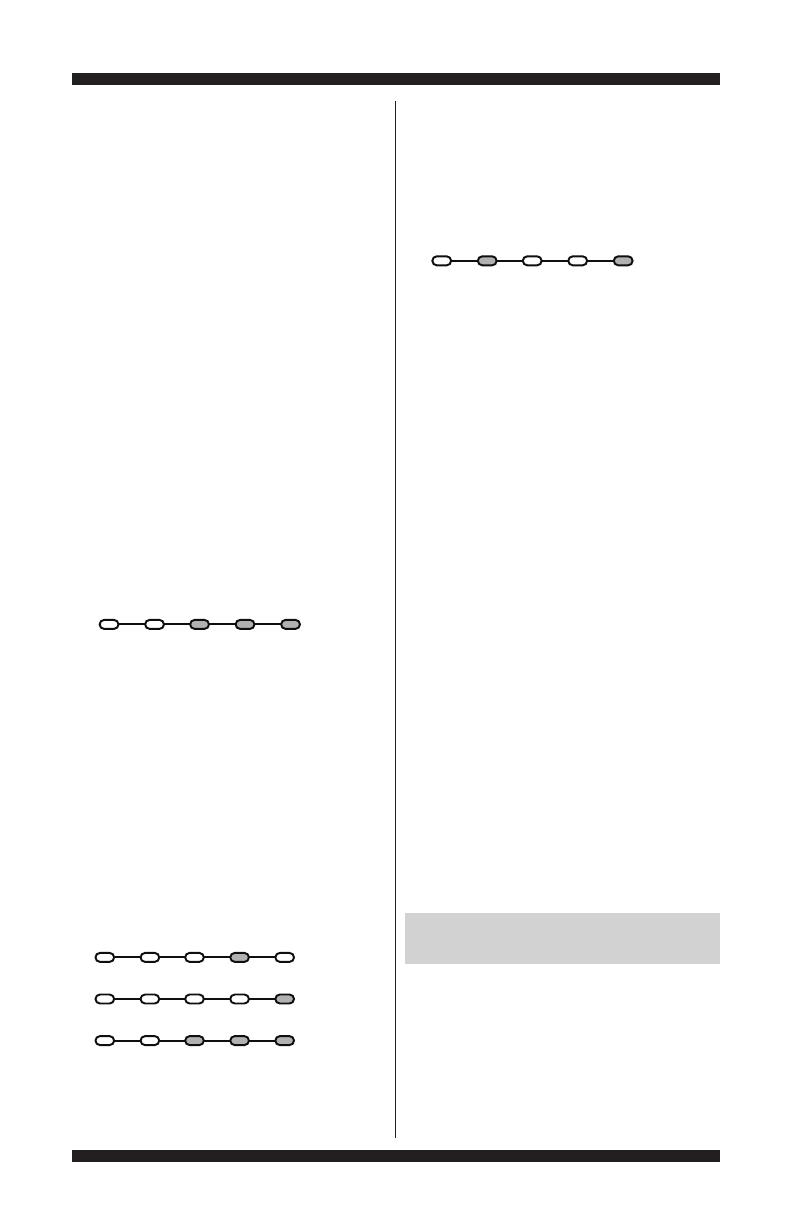
status LEDs correspond as follows:
“Spin & Done” LEDs On
Press the START button to enter Manual Test
Mode. See page 9 for manual test mode.
Upon entering the manual test mode,
the washer will have all outputs OFF.
The cycle selector knob is used to select
the output to be tested.
The START button will activate/deactivate
the selected output.
When the selected output is activated, the
corresponding status LEDs flash ON & OFF.
Press and hold the START button for 3
seconds at any time to exit Manual test mode.
IMPORTANT: As a safety feature, the lid
must be closed with lid lock enabled to
activate either Agitate or Spin Test.
NOTE: Multiple outputs may be activated
simultaneously.
NOTE: Outputs left on will time-out after 5 minutes.
CALIBRATION MODE
IMPORTANT: Calibration must be performed
when any of the following components have
been replaced: Main Control, Basket, Drive
Assembly, Suspension, Motor, and Capacitor.
Not performing calibration will result in poor
wash performance.
To access Calibration Mode, perform steps 1
and 2 of Activating the Service Diagnostic Test
Modes. Turn the cycle selector knob until the
status LEDs correspond as follows:
“Rinse” LED On
NOTE: Status LED names may vary between
makes and models.
Press the START button to begin washer
calibration. All status LEDs will turn on.
Do NOT interrupt calibration, disturb washer,
or remove power; otherwise, calibration
must be repeated.
Lid must be down to perform test.
Basket must be empty to perform test
(no water or clothes).
Calibration cycle runs for approximately
2–4 minutes. Cycle completes when door
unlocks and washer enters standby mode.
UI TEST MODE
To access UI (User Interface) Test Mode, perform
steps 1 and 2 of Activating the Service Diagnostic
Test Modes. Turn the cycle selector knob until the
status LEDs correspond as follows:
“Rinse & Spin” LEDs On
NOTE: Status LED names may vary between
makes and models. Use LED # identifications.
Press the START button to begin the UI test.
Upon entering the UI test mode, all status
LEDs will be turned ON.
Pressing the START button will turn on and
off all status LEDs, or toggle the state of
each status LED independently. (Example:
if 2 are on, and 3 are off, then 2 will be
turned off and 3 turned on.)
When rotating the cycle selector knob, each
click “indent” toggles the “Done” (5) LED.
Fill Wash Rinse Spin Done
Fill Wash Rinse Spin Done
Fill Wash Rinse Spin Done
(1)Fill (2)Wash (3)Rinse (4)Spin (5)Done
PAGE 5
FOR SERVICE TECHNICIAN’S USE ONLY
DO NOT REMOVE OR DESTROY
Turning the rotary switches will toggle
the following status LEDs on and off.
•RotarySwitch#1-toggles(1)FillLED
•RotarySwitch#2-toggles(2)WashLED
•RotarySwitch#3-toggles(3)RinseLED
•RotarySwitch#4-toggles(4)SpinLED
NOTE: The number and location of rotary
switches varies between makes and models.
Switches are read from left to right (not
counting the pressure switch), the left-most
switch being #1.
Press and hold the START button for
3 seconds at any time to exit UI test mode.
Washer will exit UI test mode after
5 minutes of inactivity or unplugging
the power cord.
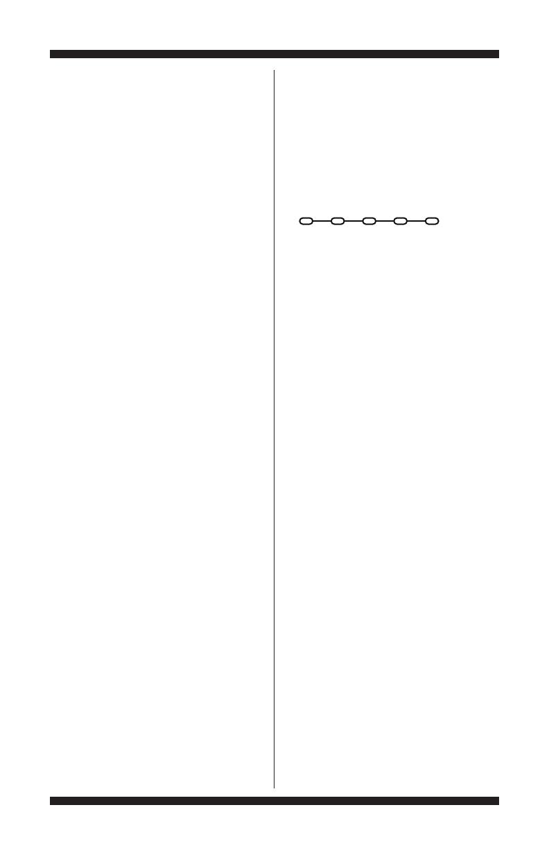
SOFTWARE VERSION DISPLAY MODE
To access Software Version Display Mode, perform
steps 1 and 2 of Activating the Service Diagnostic
Test Modes. Turn the cycle selector knob until the
status LEDs correspond as follows:
“Rinse, Spin, and Done” LEDs On
NOTE: Status LED names may vary between
makes and models.
Press the START button to begin software
display mode.
Upon entering the software version display
mode, the Major, Minor, and Test version
numbers for the software are displayed by
alternating the state of the Status LEDs in
one second intervals; the process repeats
following a pause.
For example, if the s/w version is 02.01.07,
the following sequence would be displayed:
16 8 4 2 1
02
01
07
Press and hold the START button for
3 seconds at any time to exit software
version display mode.
TACHOMETER VERIFICATION MODE
To access Tachometer Verification Mode,
perform steps 1 and 2 of Activating the Service
Diagnostic Modes. Turn the cycle selector knob
until the status LEDs correspond as follows:
“Wash and Done” LEDs On
NOTE: Status LED names may vary between
makes and models.
Press the START button to begin tachometer
verification mode.
Tachometer verification uses the status
LEDs to represent the tachometer
frequency (basket RPM).
For example, slowly turn the basket
by hand; as the basket turns, the DONE,
SPIN, RINSE, and WASH status LEDs
will illuminate one at a time in a visually
repeating cycle. The LED timing is derived
from the tachometer signal itself.
Press and hold the START button for
3 seconds at any time to exit tachometer
verification mode.
CUSTOMER VIEWABLE FAULT CODES
There are 3 fault codes that may be visible to
the customer indicated by the following Status
LEDs:
WASH LED ON (Long Fill Fault) – Refer to
“No Fill, Long Fill” on page 7 for information.
SPIN LED ON (Long Drain Fault) – Refer
to “Long Drain” on page 7 for information.
LID LOCK LED FLASHING CONTINUOUSLY
(Lid Lock Fault) – Refer to “Lid Lock Fault”
on page 6 for information.
FOR SERVICE FAULT AND ERROR CODES,
CONTINUE TO PAGES 6 AND 7
Fill Wash Rinse Spin Done
Fill Wash Rinse Spin Done
Fill Wash Rinse Spin Done
PAGE 6
FOR SERVICE TECHNICIAN’S USE ONLY
DO NOT REMOVE OR DESTROY
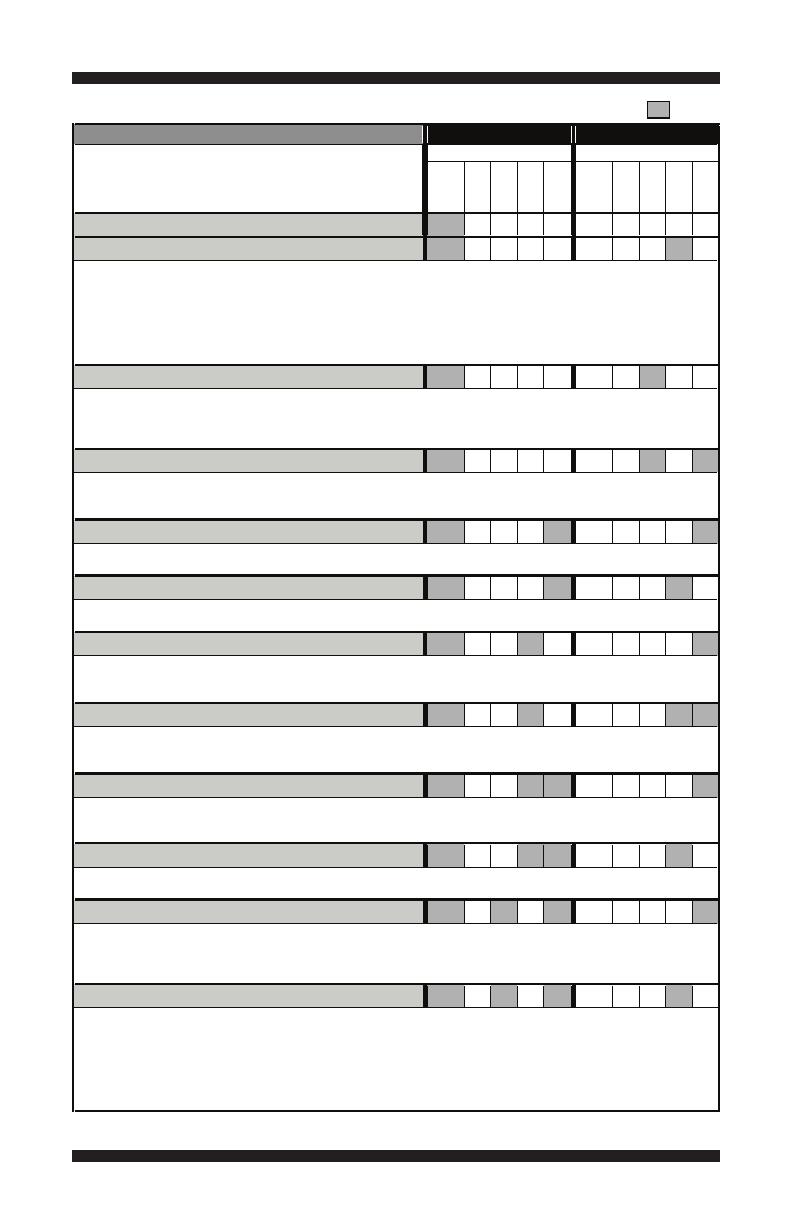
FAULT/ERROR CODES #1 — See page 3 to access Fault Code Display Mode. = ON
* If the Fill or Sensing LED is ON, the fault code is represented; if OFF, the error code is represented.
FAULT/ERROR CODE – DESCRIPTION
FILL*
WASH
RINSE
SPIN
DONE
FILL*
WASH
RINSE
SPIN
DONE
F0E2 – OVER SUDS CONDITION DETECTED
F2E1 – STUCK KEY
21
F2E3 – MISMATCH OF MAIN CONTROL & UI
22
F3E1 – PRESSURE SENSOR FAULT
21
F3E2 – INLET WATER TEMPERATURE FAULT
22
F5E1 – LID SWITCH FAULT
41
ERROR NUMBERFAULT NUMBER
Fault is displayed if lid is in locked state, but lid switch is open.
• User presses START with lid open.
• The main control cannot detect the lid switch opening and closing properly.
• See TEST #8: Lid Lock, page 18.
Fault is displayed when the Inlet Thermistor is detected to be open or shorted.
• See TEST #5: Te mperature Thermistor, page 16.
Fault is displayed when the Main Control detects an out of range pressure signal.
• Check pressure hose connection from tub to pressure sensor. Is hose pinched, kinked, plugged, or leaking air?
• See TEST #6: Water Level, page 17.
The User Interface identification does not match the expected value in the Main Control Board.
• Fault occurs during Diagnostic Test Mode if a mismatch of main control and UI is identified.
• See TEST #4: Consoles and Indicators, page 16.
Explanation & Recommended Procedure
(Status LED names may vary between makes and models)
One or more keys on the User Interface were actuated for 15 consecutive seconds.
• Fault occurs during Diagnostic Test Mode if a stuck key is detected.
• See TEST #4: Consoles and Indicators, page 16.
Status LEDs
Fault is displayed when Suds prevent the basket from spinning up to speed or the pressure sensor detects rising
suds level. The main control will flush water in attempt to clear Suds. If the water flush is unable to correct the
problem, this may indicate:
• Not using HE detergent.
• Excessive detergent usage.
• Check pressure hose connection from tub to pressure sensor. Is hose pinched, kinked, plugged, or leaking air?
• Mechanical friction on drive mechanism or basket. (Clothing between basket and tub.)
F0E4 – HIGH WATER TEMPERATURE – RINSE CYCLE
4
F0E5 – OFF BALANCE LOAD DETECTED
F1E1 – MAIN CONTROL FAULT
1
F1E2 – MOTOR CONTROL FAULT
2
Indicates a fault of the motor control section of the main control.
• See TEST #3b: Drive System – Motor, page 14.
Indicates a main control fault.
• See TEST #1: Main Control, page 12.
Fault is displayed when an off balance condition is detected.
• Check for weak suspension. Basket should not bounce up and down more than once when pushed.
• Clothing should be distributed evenly when loading.
Fault is displayed when washer detects water temperature 105° or higher during rinse cycle.
• Hot water getting in. Make sure inlet hoses are connected correctly.
• See TEST #5: Temperature Thermistor, page 16.
• If hoses are installed properly, temperature thermistor may be stuck in low resistance range.
41
F5E2 – LID LOCK FAULT
42
Fault is displayed if Lid Lock has not moved into locked position or motor cannot be powered.
• Lid is not closed completely due to interference.
• Check for lock interference with lock striker.
• Wash media buildup (detergent, lint, etc.) is preventing the lock mechanism from sliding.
• Main control detects open lid switch when attempting to lock.
• Main control cannot determine if lid lock is in a locked state.
• See TEST #8: Lid Lock, page 18.
Status LEDs
On
F0E0 – NO FAULT
8421 Off
8421
2
1
1
1
1
1
1
1
SENSING
SENSING
FE
FE
FE
FE
FE
FE
FE
FE
FE
FE
FE

PAGE 7
FOR SERVICE TECHNICIAN’S USE ONLY
DO NOT REMOVE OR DESTROY
* If the Fill or Sensing LED is ON, the fault code is represented; if OFF, the error code is represented.
FAULT/ERROR CODES #2 — See page 3 to access Fault Code Display Mode. = ON
FAULT/ERROR CODE – DESCRIPTION
SENSING
WASH
RINSE
SPIN
DONE
FILL*
WASH
RINSE
SPIN
DONE
F5E3 – LID UNLOCK FAULT
F2
F7E1 – BASKET SPEED SENSOR FAULT
41
F7E5 – SHIFTER FAULT
41
F8E1 – NO FILL, LONG FILL
81
F8E3 – OVERFLOW CONDITION
82
F8E5 – HOT, COLD REVERSED
84
F9E1 – LONG DRAIN
81
Status LEDs
ERROR NUMBERFAULT NUMBER
Fault is displayed when main control senses water level that exceeds the washer’s capacity.
• May signify problem with inlet water valves.
• Check pressure hose connection from tub to pressure sensor. Is hose pinched, kinked, plugged, or leaking air?
• Onboard pressure transducer or off-board pressure switch fault (depending on model).
• See TEST #2: Valves, page 13 and TEST #6: Water Level, page 17.
Fault is displayed when the hot and cold inlet hoses are reversed.
• Make sure inlet hoses are connected correctly.
• If hoses are installed properly, temperature thermistor may be stuck in low resistance range.
• See TEST #2: Valves, page 13 and TEST #5: Temperature Thermistor, page 16.
Fault is displayed when the main control cannot determine speed of basket, or speed changes too quickly.
• Locked rotor—check that basket, impeller, and motor can rotate freely.
• Check harness connections from main control to motor and shifter.
• See TEST #3a: Drive System–Shifter, page 13.
Fault is displayed when the main control cannot determine position of shifter.
• Check harness connections from main control to motor and shifter.
• Observe shifter operation.
• See TEST #3a: Drive System–Shifter, page 13.
Fault is displayed if Lid Lock has not moved into unlocked position or motor cannot be powered.
• Check for lock interference with lock striker.
• Main control cannot determine if lid lock is in an unlocked state.
• See TEST #8: Lid Lock, page 18.
Fault is displayed when the water level does not change for a period of time OR water is present but main control
does not detect the water level changing.
• Is water supply connected and turned on?
• Low water pressure; fill times longer than six minutes. Are hose screens plugged?
• Check for proper drain hose installation. Is water siphoning out of the drain hose?
• Drain hose must not be more than 4.5" (113mm) into the drain pipe.
• Check pressure hose connection from tub to pressure sensor. Is hose pinched, kinked, plugged, or leaking air?
• See TEST #2: Valves, page 13.
Status LEDs
Fault is displayed when the water level does not change after the drain pump is on for 10 minutes.
• Is the drain hose or the drain pump clogged? Check tub sump under impeller for obstructions.
• Is the drain hose height greater than 96"?
• Check pressure hose connection from tub to pressure sensor. Is hose pinched, kinked, plugged, or leaking air?
• Is the pump running? If not, see TEST #7: Drain Pump, page 17.
1
F5E4 – LID NOT OPENED BETWEEN CYCLES
4
Fault is displayed if the following conditions occur:
• User presses START after several consecutive washer cycles without opening lid.
• See TEST #8: Lid Lock, page 18.
4
F7E6 – MOTOR FAULT
2
Indicates an open clockwise or counterclockwise circuit of the motor.
• See TEST #3b: Drive System–Motor, page 14.
F7E7 – MOTOR UNABLE TO REACH TARGET RPM
44
Fault is displayed when basket speed sensor detects that target RPM was not reached.
• Mechanical friction on drive mechanism or basket (clothing between basket and tub).
2
• Weak motor or run capacitor, or no connection to run capacitor.
• Load off balance. Clothing should be distributed evenly when loading.
• See TEST #3b: Drive System–Motor, page 14.
1
E482
1
48
1
21
421
4421
21
1
1
1
Explanation & Recommended Procedure
(Status LED names may vary between makes and models)
FILL*
SENSING
FE
FE
FE
F
E
FE
FE
• Not pumping—pressure switch closed or shorted in standby, or after washer completes a cycle.
FE
F E
FE

PAGE 8
FOR SERVICE TECHNICIAN’S USE ONLY
DO NOT REMOVE OR DESTROY
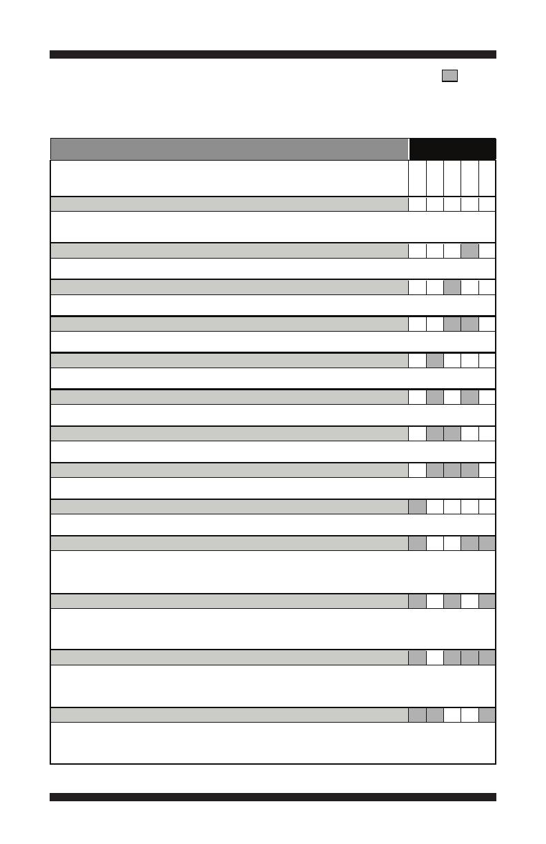
AUTOMATIC TEST MODE — See page 4 to access Automatic Test Mode. = ON
Press the START button to begin the Automatic Test.
IMPORTANT: Lid must be closed and locked to perform Automatic Test.
FUNCTION
Recommended Procedure
(Status LED names may vary between makes and models)
WASH
RINSE
SPIN
DONE
LID LOCK
LID WILL LOCK
On
COLD VALVE WILL ACTUATE
On
HOT VALVE WILL ACTUATE
On
RESERVED FOR FUTURE DEVELOPMENT
On
RESERVED FOR FUTURE DEVELOPMENT
On
RESERVED FOR FUTURE DEVELOPMENT
On
HOT & COLD VALVE WILL ACTUATE
On
SHIFTER MOVES TO AGITATION POSITION
On
MOTOR AGITATES
On
DRAIN PUMP WILL ACTUATE
On
SHIFTER MOVES TO SPIN POSITION
On
MOTOR SPINS
On
LID REMAINS LOCKED UNTIL WASHER SENSES A STOPPED
BASKET
On
LID WILL UNLOCK AND CYCLE COMPLETES
STATUS LEDs
If motor does not agitate, go to Manual Test: Gentle or Heavy Agitation, page 9.
If water is not draining, go to Manual Test: Drain, page 9.
If basket is not turning, go to Manual Test: Low or High Spin, page 9.
Washer will pause for 5 seconds.
Washer will pause for 5 seconds.
Hot & cold water valves will actuate for the specified time period.
If motor does not agitate, go to Manual Test: Gentle or Heavy Agitation, page 9.
Motor must be at “0” RPM. If lid does not lock, go to Manual Test: Lid Lock, page 9.
If water is not present, or temperature is wrong, go to Manual Test: Cold Valve, page 9.
If lid does not unlock, go to Manual Test: Lid Lock, page 9.
If water is not present, or temperature is wrong, go to Manual Test: Hot Valve, page 9.
Washer will pause for 5 seconds.
Basket must stop spinning (0 RPM) before test continues to next phase. Time for basket to stop spinning may vary
from 30 seconds up to 2 minutes.
If basket is not turning, go to Manual Test: Low or High Spin, page 9.
Est. TIME
In Seconds
1
5
5
5
5
5
45
~5-15
10
~30-40
~5-15
10
~30-45
1
~3 min
1
2
21
4
4 1
42
421
8
8 1
8 2
8 2 1
84
84 1
842
PAGE 9
FOR SERVICE TECHNICIAN’S USE ONLY
DO NOT REMOVE OR DESTROY
MANUAL TEST MODE — See page 4 to access Manual Test Mode. = ON
Pressing the START button will activate/deactivate each output. When the output is activated, the
corresponding Status LEDs will flash. IMPORTANT: Lid must be closed and locked to perform SPIN
& AGITATE tests.
OUTPUT
Output Details
NOTE: Outputs will time-out after 5 minutes.
WASH
RINSE
SPIN
DONE
LID LOCK
LID LOCK
COLD VALVE
1
HOT VALVE
2
RESERVED FOR FUTURE DEVELOPMENT
2
RESERVED FOR FUTURE DEVELOPMENT
4
RESERVED FOR FUTURE DEVELOPMENT
4
RESERVED FOR FUTURE DEVELOPMENT
4
DRAIN
4
RESERVED FOR FUTURE DEVELOPMENT
8
LOW SPIN – To perform test, lid must be closed and locked.
8 On
HIGH SPIN – To perform test, lid must be closed and locked.
8 On
GENTLE AGITATION – To perform test, lid must be closed and locked.
HEAVY AGITATION – To perform test, lid must be closed and locked.
Shifts from idle motor to heavy CW/CCW agitation. NOTE: Allow up to 15 seconds for shifter to reposition.
IMPORTANT: To activate Heavy Agitation, RPM must read “0” and lid must be closed with lid lock enabled. If lid is not
closed, status LEDs will flash on and off.
• If motor does not agitate, go to TEST #3a & 3b: Drive System (Shifter & Motor), pages 13 & 14.
STATUS LEDs
If selected, status LEDs will flash on and off.
Spins basket from 0 to 500 RPM. NOTE: Allow up to 15 seconds for shifter to reposition.
IMPORTANT: To activate Low Spin, RPM must read “0” and lid must be closed with lid lock enabled.
If lid is not closed, status LEDs will flash on and off. IMPORTANT: Water in tub must be drained before test.
• If motor does not spin, go to TEST #3a & 3b: Drive System (Shifter & Motor), pages 13 & 14.
Spins basket from 0 to maximum RPM. NOTE: Allow up to 15 seconds for shifter to reposition.
IMPORTANT: To activate High Spin, RPM must read “0” and lid must be closed with lid lock enabled.
If lid is not closed, status LEDs will flash on and off. IMPORTANT: Water in tub must be drained before test.
• If motor does not spin, go to TEST #3a & 3b: Drive System (Shifter & Motor), pages 13 & 14.
Shifts from idle motor to gentle CW/CCW agitation. NOTE: Allow up to 15 seconds for shifter to reposition.
IMPORTANT: To activate Gentle Agitation, RPM must read “0” and lid must be closed with lid lock enabled. If lid is not
closed, status LEDs will flash on and off.
• If motor does not agitate, go to TEST #3a & 3b: Drive System (Shifter & Motor), pages 13 & 14.
If selected, status LEDs will flash on and off.
If selected, status LEDs will flash on and off.
If selected, status LEDs will flash on and off.
Turns ON and turns OFF the drain pump.
• If pump does not turn on, go to TEST #7: Drain Pump, page 17.
Lock and unlock the lid. NOTES: When lock is enabled, the “Lid Lock” LED will turn ON. Will only lock when lid is closed.
Will only unlock when basket RPM is 0. If lid is not closed, washer will flash status LEDs on and off.
• If lid does not lock or unlock, go to TEST #8: Lid Lock, page 18.
Turns ON and turns OFF cold water valve.
• If valve does not turn on, go to TEST #2: Valves, page 13.
Turns ON and turns OFF hot water valve.
• If valve does not turn on, go to TEST #2: Valves, page 13.
If selected, status LEDs will flash on and off.
On
On
1
1
2
2 1
1
2
8 2 1
8 4
PAGE 10
FOR SERVICE TECHNICIAN’S USE ONLY
DO NOT REMOVE OR DESTROY
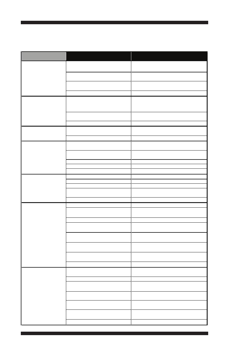
TROUBLESHOOTING GUIDE NOTE: Always check for error codes first (pgs. 6–7).
Some tests will require accessing components. See Figures 7 & 8, page 19, for component locations.
For detailed troubleshooting procedures, refer to “Troubleshooting Tests” beginning on page 12.
PROBLEM POSSIBLE CAUSE
No power to washer.
Connection problem between AC
plug and main control.
Main control not properly installed
in console.
Main control problem.
Lid lock mechanism not functioning.
User Interface problem.
Main control problem.
User Interface problem.
Main control problem.
No water supplied to washer.
Plugged filter/screen.
Drain hose installation.
Valve problem.
Main control problem.
Pressure hose.
Valve problem.
Washer requires calibration.
Main control problem.
OVERFILLS
WON’T POWER UP
•No operation
• No Status LEDs
WON’T START CYCLE
No response when
Start Button is pressed.
UI WON’T ACCEPT
SELECTIONS
WON’T FILL
CHECKS & TESTS
Check power at outlet, check circuit
breakers, fuses, or junction box connections.
Check the AC power cord for continuity.
See TEST #4: Console and Indicators,
page 16.
See TEST #1: Main Control, page 12.
1. Lid not closed due to interference.
2. Lock not closed due to interference.
3. See TEST #8: Lid Lock, page 18.
See TEST #4: Console and Indicators,
page 16.
See TEST #1: Main Control, page 12.
See TEST #4: Console and Indicators,
page 16.
See TEST #1: Main Control, page 12.
1. Check water connections to washer.
2. Verify hot and cold water supply is on.
Check for plugged filter or screen in the
water valve or hoses.
Check for proper drain hose installation.
See TEST #2: Valves, page 13.
See TEST #1: Main Control, page 12.
See TEST #6: Water Level, page 17.
See TEST #2: Valves, page 13.
Perform washer calibration on page 4.
See TEST #1: Main Control, page 12.
Pressure switch or onboard
transducer.
See TEST #6: Water Level, page 17.
Is lid lock showing open during
the cycle?
Drive belt.
Harness connections.
Shifter problem.
Motor problem.
Main control problem.
WON’T SPIN
See TEST #8: Lid Lock, page 18.
Verify that drive belt is not damaged.
Check harness connections between main
control and drive system.
See TEST #3a: Drive System–Shifter,
page 13.
See TEST #3b: Drive System–Motor,
page 14.
See TEST #1: Main Control, page 12.
Tachometer problem. No tub movement or tub speed out of normal
range (obstruction/belt/motor).
Water covering impeller?
Is lid lock showing open during
the cycle?
Drive belt.
Harness connections.
Shifter problem.
Motor problem.
Main control problem.
WON’T AGITATE
See TEST #6: Water Level, page 17.
See TEST #8: Lid Lock, page 18.
Verify that drive belt is not damaged.
Check harness connections between main
control and drive system.
See TEST #3a: Drive System–Shifter,
page 13.
See TEST #3b: Drive System–Motor,
page 14.
See TEST #1: Main Control, page 12.
Tachometer problem. No tub movement or tub speed out of normal
range (obstruction/belt/motor).

PAGE 11
FOR SERVICE TECHNICIAN’S USE ONLY
DO NOT REMOVE OR DESTROY
Some tests will require accessing components. See Figures 7 & 8, page 19, for component locations.
For detailed troubleshooting procedures, refer to “Troubleshooting Tests” beginning on page 12.
TROUBLESHOOTING GUIDE (continued)
PROBLEM POSSIBLE CAUSE
Drain hose installation.
Plugged drain hose.
Obstructions to drain pump.
Harness connections.
Drain pump.
Main control problem.
Oversuds.
Load is tangling.
Incorrect water level.
Clothes wet after cycle is complete
(not water saturated, but very damp).
Load not rinsed.
Not cleaning clothes.
Fabric damage.
Wrong option or cycle selection.
WON’T DRAIN
POOR WASH
PERFORMANCE
Please reference
Use & Care Guide
CHECKS & TESTS
Check for proper drain hose installation.
Make sure it is not inserted more than 4.5"
(113mm).
Check drain hose for obstructions.
Check tub sump under agitator plate &
basket for obstructions.
Check harness connections between main
control and drain pump.
See TEST #7: Drain Pump, page 17.
See TEST #1: Main Control, page 12.
1. Verify use of HE detergent.
2. Excessive detergent usage.
1. Washer not loaded properly.
2. Perform washer calibration on page 4.
1. Perform washer calibration on page 4.
2. See TEST #2: Valves, page 13.
3. See TEST #6: Water Level, page 17.
1. Overloaded washer.
2. Oversuds (see above).
3. Items caught in tub sump.
7. See TEST #7: Drain Pump, page 17.
1. Check proper water supply.
2. Not using HE detergent.
3. Washer not loaded properly.
5. See TEST #2: Valves, page 13.
1. Washer not loaded properly.
2. Not using HE detergent.
3. Not using correct cycle.
4. Shifter not moving into position
1. Washer overloaded.
2. Bleach added incorrectly.
3. Sharp items in tub.
Refer customer to “Use & Care Guide”.
4. Weak suspension.
CYCLE TIME LONGER
THAN EXPECTED
Oversuds. 1. Verify use of HE detergent.
2. Excessive detergent usage.
Off balance. 1. Load is off balance.
2. Balance ring water leak.
Weak suspension. Basket should not bounce up and down
more than once when pushed.
Draining slowly.Check for pump or drain hose obstructions.
Water pressure drop.Results in longer Fill time.
Friction or drag on drive. Check motor and bearings; check for
clothes between tub and basket.
5. Shifter not moving into position
(see TEST #3a).
4. Shifter not moving into position
(see TEST #3a).
(see TEST #3a).
Water hose installation.
Temperature thermistor.
Main control problem.
INCORRECT WATER
TEMPERATURE
Make sure inlet hoses are connected
properly.
See TEST #5: Temperature Thermistor,
page 16.
See TEST #1: Main Control, page 12.
Valve problem. See TEST #2: Valves, page 13.
6. Cold/Rinse water > 105°F.
PAGE 12
FOR SERVICE TECHNICIAN’S USE ONLY
DO NOT REMOVE OR DESTROY
TROUBLESHOOTING TESTS
TEST #1: Main Control
This test checks for incoming and outgoing supplies
to and from the main control. This test assumes
that proper voltage is present at the outlet.
1. Unplug washer or disconnect power.
2. Remove console to access main control.
3. Verify that ALL connectors are inserted
all the way into the main control.
4. Plug in washer or reconnect power.
5. With a voltmeter set to AC, connect black
probe to J7-3 (Neutral) and red probe to J7-1 (L1).
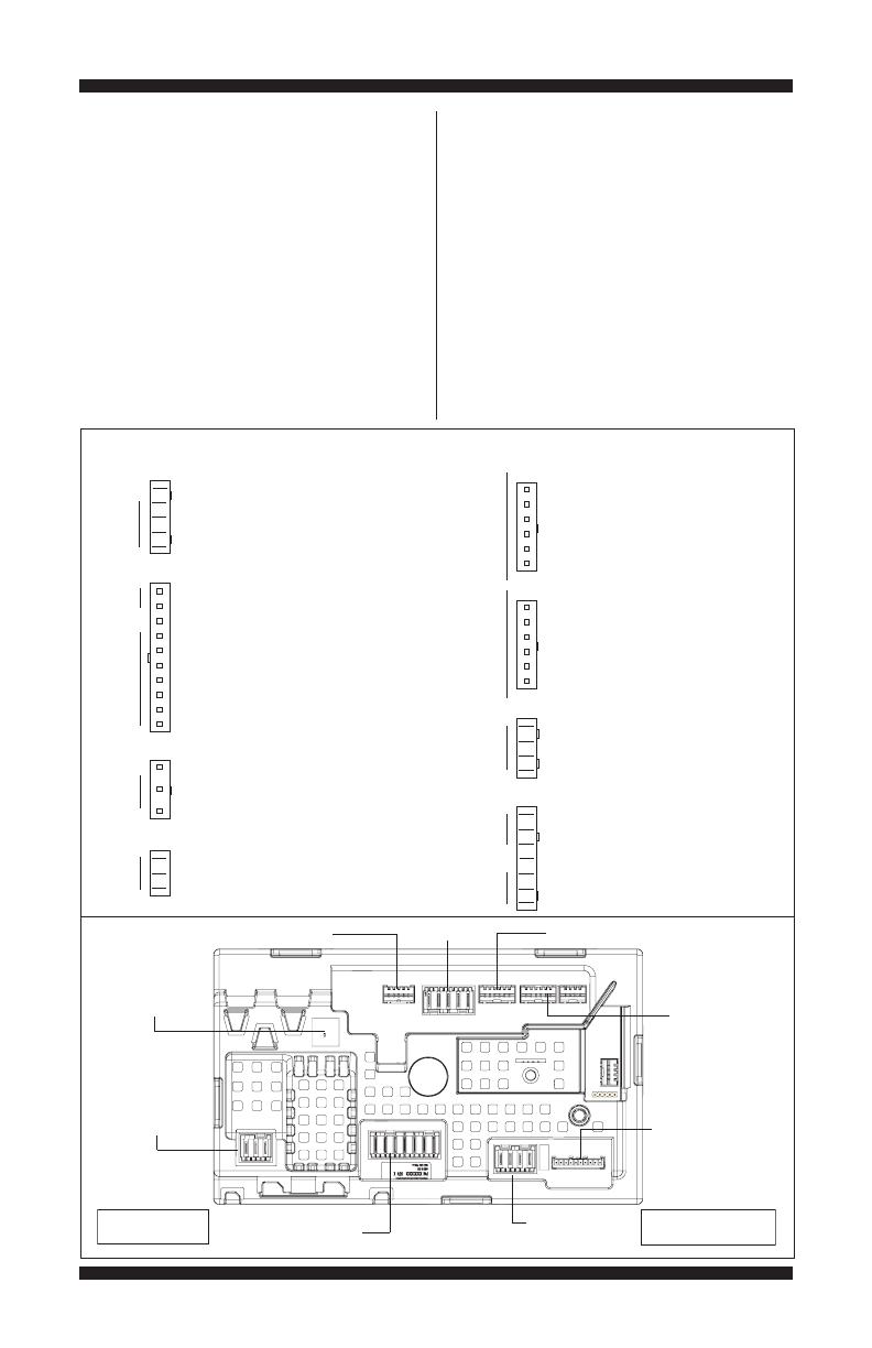
Main Control Board Connectors and Pinouts (Figure 3)
J2-5 OPEN
J2-4 BLK +13VDC
J2-3 GRY -5VDC (CIRCUIT GND)
J2-2 PNK RPM INPUT
J2-1 BLU SHIFTER POSITION INPUT
J3-10 BLK TEMP THERMISTOR INPUT (HYBRID)
J3-9 BLK TEMP THERMISTOR GND (HYBRID)
J3-8 OPEN
J3-7 OPEN
J3-6 OPEN
J3-5 BLU COLD VALVE (L1)
J3-4 RED HOT VALVE (L1)
J3-3 OPEN
J3-2 OPEN
J3-1 WHT NEUTRAL
J4-3 BLU PRESS SWITCH INPUT
J4-2 OPEN
J4-1 BLU -5VDC (CIRCUIT GND)
J7-3 BLK NEUTRAL
J7-2 GRN CHASSIS GROUND
J7-1 BLK L1
J2
J3
J7
J4
J10
J11
J16
J15
SHIFTER VALVES TEMP
POWER
CORD
PRESS
SW
ROTARY ENCODERSROTARY ENCODERS
LID LOCK
DRAIN MOTOR
J10-6 RED ROW 4
J10-5 RED ROW 5
J10-4 RED COLUMN 0
J10-3 RED COLUMN 1
J10-2 RED COLUMN 2
J10-1 RED COLUMN 3
J11-6 BLK ROW 2
J11-5 BLK ROW 3
J11-4 BLK COLUMN 0
J11-3 BLK COLUMN 1
J11-2 BLK COLUMN 2
J11-1 BLK COLUMN 3
J15-4 RED LOCK SWITCH
J15-3 WHT NEUTRAL
J15-2 BLU LID SWITCH INPUT
J15-1 YEL LOCK SWITCH SOLENOID (L1)
J16-7 ORN MOTOR CCW WINDING (L1)
J16-6 RED MOTOR CW WINDING (L1)
J16-5 WHT MOTOR (NEUTRAL)
J16-4 OPEN
J16-3 LT BLU DRAIN PUMP MOTOR (L1)
J16-2
W/ BLU
SHIFTER MOTOR (NEUTRAL)
J16-1 BRN SHIFTER MOTOR (L1)
If 120VAC is present, go to step 6.
If 120VAC is not present, check the AC
power cord for continuity (See Figures 9 or 10).
6. Is the “Diagnostic LED” ON or OFF? (See
Figure 3 below for LED location.)
ON: (+5VDC present) continue to step 7.
OFF: (+5VDC missing) proceed to step 8.
7. With a voltmeter set to DC, connect black
probe to J2-3 (Circuit Gnd) and red probe to
J2-4 (+13VDC).
If +13VDC is present, main control
supplies are good.
If +13VDC is not present, go to step 8.
Diagnostic
LED
J4-Pressure Switch *
J7-Power
Cord
J16-PSC Motor/Drain
J15-Lid Lock
J3-Temperature
Sensor/Valves
= represents pin-1
J2-Shifter
J10-Rotary
Encoders *
J11-Rotary Encoders
* Not available on all models
J7
J2
J4
J3
J16
J15
J11
J10
PAGE 13
FOR SERVICE TECHNICIAN’S USE ONLY
DO NOT REMOVE OR DESTROY
8. Check if shifter assembly is affecting the
main control DC supplies.
a. Unplug washer or disconnect power.
b. Remove connector J2 from main control.
c. Plug in washer or reconnect power.
d. Repeat steps 6 and 7. Perform the +13VDC
check inside header J2 on the board – do not
short pins together.
If one or more DC voltages are still missing,
go to step 9.
If the DC voltages return, check for short in
harness between main control and shifter assy.
If harness and connections are good,
replace shifter assembly.
9. Main Control has malfunctioned.
a. Unplug washer or disconnect power.
b. Replace the main control.
c. Reassemble all parts and panels.
d. Plug in washer or reconnect power. Calibrate
washer and perform Automatic Test to verify repair.
TEST #2: Valves
This test checks the electrical connections
to the valves, and the valves themselves.
1. Check the relays and electrical connections
to the valves by performing the Cold and Hot
Valve tests under Manual Test Mode on page 9.
Each test activates and deactivates the selected
valve. The following steps assume one (or
more) valve(s) did not turn on.
2. For the valve(s) in question check the
individual solenoid valves:
a. Unplug washer or disconnect power.
b. Remove console to access main control.
c. Remove connector J3 from main control.
Refer to main control diagram on page 12.
d. Check harness connection to solenoid valves.
3. Check resistance of the valve coils across
the following J3 connector pinouts:
Resistance should be 890–1.3k Ω.
If resistance readings are tens of ohms
outside of range, replace the valve assembly.
If resistance readings are within range,
replace main control and calibrate washer.
Perform Automatic Test to verify repair.
TEST #3a: Drive System – Shifter
This test checks connections, shifter motor,
switch, and optical sensor.
NOTE: Refer to Figure 4, “Shifter Assembly Strip
Circuit” on page 14 for tests and measurements.
IMPORTANT: Drain water from tub before
accessing bottom of washer.
Functional Check:
1. Check the shifter and electrical connections
by performing both the Spin AND Agitate test
under Manual Test Mode on page 9. The following
steps assume that this step was unsuccessful.
2. Unplug washer or disconnect power.
3. Check to see if basket will turn freely.
If basket turns freely, go to step 4.
If basket does not turn freely, determine what
is causing the mechanical friction or lockup.
4. Remove console to access main control.
5. Visually check that the J2 and J16 connectors
are inserted all the way into the main control.
If visual checks pass, go to step 6.
If connectors are not inserted properly,
reconnect J2 and J16 and repeat step 1.
Shifter Motor:
6. Remove connector J16 from main control.
With an ohmmeter, verify resistance of the shifter
motor across the following J16 connector pinouts:
Resistance should be 2k to 3.5k Ω.
If values are correct, reconnect J16 and
proceed to step 7.
If values are open or out of range,
go to step 13.
7. Plug in washer or reconnect power.
8. With a voltmeter set to AC, connect the
black probe to J16-2 (N) and red probe to
J16-1 (L1). Activate shifter motor by switching
between Spin and Agitate modes. Energize
outputs using Manual Test Mode on page 9.
IMPORTANT: Lid must be closed with Lid Lock
enabled to run the SPIN and AGITATE tests.
NOTE: It will take 4–15 seconds for the shifter
to change states.
If 120VAC is present, go to step 9.
If 120VAC is not present, go to step 17.
tuoniPevlaV
4 & 1 ,3JevlaV toH
5 & 1 ,3JevlaV dloC
Com
p
onent J16 Connector Pinout
Shifter Motor J16, 1 & 2
PAGE 14
FOR SERVICE TECHNICIAN’S USE ONLY
DO NOT REMOVE OR DESTROY
Shifter Switch:
9. With a voltmeter set to DC, connect the
black probe to J2-3 (Circuit Gnd) and red
probe to J2-1 (Shifter Switch). In manual test
mode, switch between Spin and Agitate modes.
Voltage should toggle between 0 and +5VDC.
SPIN = +5 VDC
AGITATE = 0 VDC
If voltage corresponds to setting, go to step 10.
If voltage does not switch, go to step 12.
Optical Sensor:
10. With a voltmeter set to DC, connect the
black probe to J2-3 (Circuit Gnd) and red
probe to J2-4 (+13VDC).
If +13VDC is present, go to step 11.
If +13VDC is not present, go to step 17.
11. Activate Tachometer Verification Mode
from the Service Diagnostic Test Modes (see
page 5). Slowly turn the basket by hand. The 4
status LEDs should illuminate one at a time to
represent basket RPM.
If the tachometer is not verified, go to step 12.
If the tachometer is verified, go to step 17.
12. Unplug washer or disconnect power.
13. Tilt washer back to access the bottom
of the washer and the drive motor area.
14. Visually check the electrical connections
to the shifter.
If visual check passes, go to step 15.
If connections are loose, reconnect the
electrical connections and repeat step 1.
15. With an ohmmeter, check the harness for
continuity between the shifter and main control
using the pinouts in the following chart.
If there is continuity, go to step 16.
If there is no continuity, replace the lower
washer harness and repeat step 1.
16. Replace the shifter assembly.
a. Unplug washer or disconnect power.
b. Replace shifter assembly.
c. Reassemble all parts and panels.
d. Plug in washer or reconnect power. Calibrate
washer and perform Automatic Test to verify repair.
17. If the preceding steps did not correct the
problem, replace the main control.
a. Unplug washer or disconnect power.
b. Replace the main control.
c. Reassemble all parts and panels.
d. Plug in washer or reconnect power. Calibrate
washer and perform Automatic Test to verify repair.
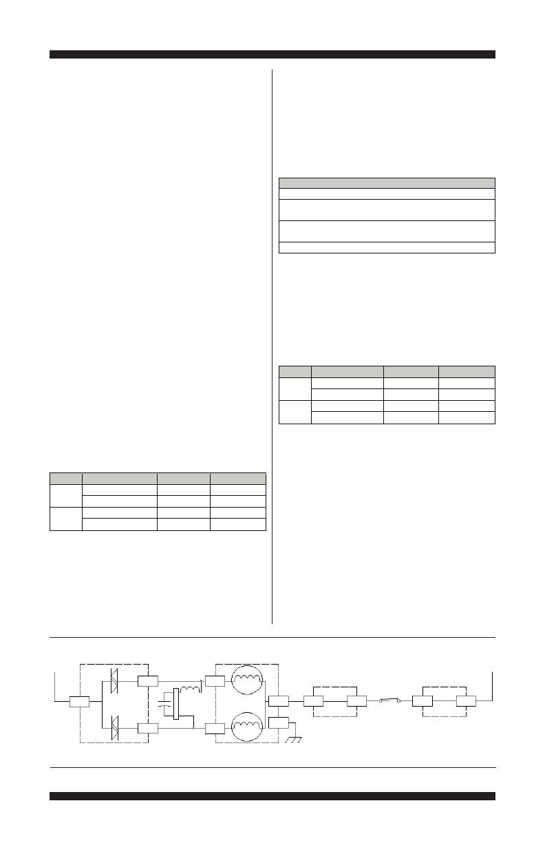
TEST #3b: Drive System – Motor
This test checks the motor, motor windings,
wiring, and start capacitor.
NOTE: Refer to Figure 5, “PSC Motor Strip
Circuit” on page 15 for tests and measurements.
IMPORTANT: Drain water from tub before
accessing bottom of washer.
1. Check the motor and electrical connections
by performing the Gentle or Heavy Agitation test
under Manual Test Mode on page 9. The following
steps assume that this step was unsuccessful.
2. Unplug washer or disconnect power.
3. Check to see if basket will turn freely.
If basket turns freely, go to step 4.
If basket does not turn freely, determine what
is causing the mechanical friction or lockup.
4. Remove console to access main control.
5. Visually check that the J2 and J16 connectors
are inserted all the way into the main control.
Figure 4 - Shifter Assembly Strip Circuit (Shifter Switch: Open = SPIN, Closed = AGITATE)
Main Control
Shifter Assy
J2-3
J16-1
J7-1
L1
Main Control
J2-4
J2-2
J16-2
J2-1Pin 7
Pin 6
Pin 3
Pin 5
Pin 4
Pin 2
J7-3
K8
Circuit Ground
N
+13VDC
120VAC
Motor
Shifter Switch
Optical
Sensor
Shifter Position
Input
RPM Input
Motor Resistance 2k to 3.5k ohms
Shifter Motor Relay
Shifter to Main Control & Drain Pum
p
Shifter Connector Pin-2 to Main Control J16-2
Shifter Connector Pin-3 to Main Control J16-1
Shifter Connector Pin-4 to Main Control J2-4
Shifter Connector Pin-5 to Main Control J2-3
Shifter Connector Pin-6 to Main Control J2-2
Shifter Connector Pin-7 to Main Control J2-1
PAGE 15
FOR SERVICE TECHNICIAN’S USE ONLY
DO NOT REMOVE OR DESTROY
Figure 5 - PSC Motor Strip Circuit (shown in ON position)
Main Control
CW TRIAC
Main Control Main Control
CCW TRIAC
J15-3
J15-4J16-5
Pin 9
Pin 1
Pin 6
Pin 3
J16-7
J16-6
J7-3
J7-1
PSC Motor
Run
Cap
CW Winding*
CCW Winding*
Lock Switch
N
L1
* 1/3 HP Motor – Each Winding 3.5 to 6 ohms/ * 1/4 HP Motor – Each Winding 5 to 9.5 ohms
1
3
If visual checks pass, go to step 6.
If connectors are not inserted properly,
reconnect J2 and J16 and repeat step 1.
6. Plug in washer or reconnect power. Run the
Gentle Agitation test under Manual Test Mode
on page 9.
7. With a voltmeter set to AC, connect black
probe to J16-5 (N) and red probe to J16-6
(CW Winding).
If 120VAC is cycling ON during CW rotation,
go to step 8.
If 120VAC is not present, go to Test #1:
Main Control, page 12.
8. With a voltmeter set to AC, connect black probe
to J16-5 (N), red probe to J16-7 (CCW Winding).
If 120VAC is cycling ON during CCW
rotation, go to step 9.
If 120VAC is not present, go to Test #1:
Main Control, page 12.
9. Unplug washer or disconnect power.
10. Remove connector J16 from main control.
With an ohmmeter, check resistance of motor
windings across the following J16 connector
pinouts:
NOTE: If the console has a cycle selector knob
and 4 rotary switches, the motor size is 1/3 HP.
If values are open or out of range, go to step 11.
If values are correct, go to step 15.
11. Tilt washer back to access drive system.
12. Visually check the mounting bracket and
electrical connections to the motor and shifter.
If visual check passes, go to step 13.
If connections are loose, reconnect the
electrical connections, reassemble motor
cover, and repeat step 1.
13. With an ohmmeter, check the harness
for continuity between the main control, motor,
and run capacitor using the following test points.
If there is continuity, go to step 14.
If there is no continuity, replace the lower
machine harness and repeat step 1.
14. With an ohmmeter, check resistance of motor
windings at the following motor connections.
NOTE: If the console has a cycle selector knob
and 4 rotary switches, the motor size is 1/3 HP.
If values are open or out of range, replace
motor.
If values are correct, go to step 15.
15. Test Motor Run Capacitor. NOTE: A faulty
capacitor may cause the motor to “hum”, not
start, or turn slowly.
a. Discharge the capacitor by touching the leads
of a 20,000 Ω resistor to the two terminals.
b. Disconnect the wires from the capacitor
terminals.
c. With an ohmmeter, measure across the
terminals and note reading.
If a steady increase in resistance is noted,
continue to step 16.
Motor Winding J16 Pinout
CW Winding J16, 5 & 6
CCW Winding J16, 5 & 7
Size
1/4 HP
Resistance
5 to 9.5 Ω
5 to 9.5 Ω
CW Winding J16, 5 & 6
CCW Winding J16, 5 & 7
1/3 HP
3.5 to 6 Ω
3.5 to 6 Ω
Motor Harness Check
Motor Connector Pin-1 to Chassis Ground
Motor Connector Pin-3 to Main Control J16-7
Motor Connector Pin-3 to Run Capacitor Pin-3
Motor Connector Pin-6 to Main Control J16-6
Motor Connector Pin-6 to Run Capacitor Pin-1
Motor Connector Pin-9 to Main Control J16-5
Motor Winding Motor Pinout
CW Winding Pins 6 & 9
CCW Winding Pins 3 & 9
Size
1/4 HP
Resistance
5 to 9.5 Ω
5 to 9.5 Ω
CW Winding Pins 6 & 9
CCW Winding Pins 3 & 9
1/3 HP
3.5 to 6 Ω
3.5 to 6 Ω
Inductive
Wire Loop
PAGE 16
FOR SERVICE TECHNICIAN’S USE ONLY
DO NOT REMOVE OR DESTROY
If the capacitor is either shorted or open,
replace capacitor, calibrate, and repeat step 1.
16. If the preceding steps did not correct the
motor problem, replace the main control.
a. Unplug washer or disconnect power.
b. Replace the main control.
c. Reassemble all parts and panels.
d. Plug in washer or reconnect power. Calibrate
washer and perform Automatic Test to verify repair.
TEST #4: Console and Indicators
Console and Indicators Check:
This test is performed when any of the
following situations occurs during “UI Test
Mode” on page 4.
3None of the LEDs light up
3One or more Status LEDs are flashing
3Turning rotary switch does not toggle LED
None of the LEDs light up:
1. Unplug washer or disconnect power.
2. Access the main control and visually check
that ALL connectors are inserted all the way
into their respective headers.
3. Visually check that the main control
assembly is properly inserted in the console.
4. If both visual checks pass, follow procedure
under TEST #1, “Main Control” on page 12 to
verify supply voltages.
5. To verify repair, activate the Service
Diagnostic Mode, and then perform UI Test
Mode on page 4.
One or more Status LEDs are flashing:
If one or more of the status LEDs are flashing
(on and off in 0.5 second intervals), refer to
the following notes to identify the switch(es)
in question. Reference the appropriate wiring
diagrams on pages 20-21 when performing
the following procedures.
a. Verify the switch connector is inserted
all the way into the main control.
b. Check the harness between the switch and
main control for continuity. Check for shorts.
c. Replace the switch.
d. Replace the main control.
NOTE 1: The number and location of rotary
switches varies between makes and models.
NOTE 2: Regardless of location, switches are
read from left to right (not counting the pressure
switch), the left-most switch being #1.
NOTE 3: Each rotary switch and the cycle
selector knob is represented by the following
status LEDs:
•RotarySwitch#1-toggles(1)FillLED
•RotarySwitch#2-toggles(2)WashLED
•RotarySwitch#3-toggles(3)RinseLED
•RotarySwitch#4-toggles(4)SpinLED
•CycleSelectKnob-toggles(5)DoneLED
NOTE 4: Status LED names may vary between
makes and models. Use LED # identification.
Turning rotary switch does not toggle LED:
Perform the procedures under “One or more
Status LEDs are flashing.”
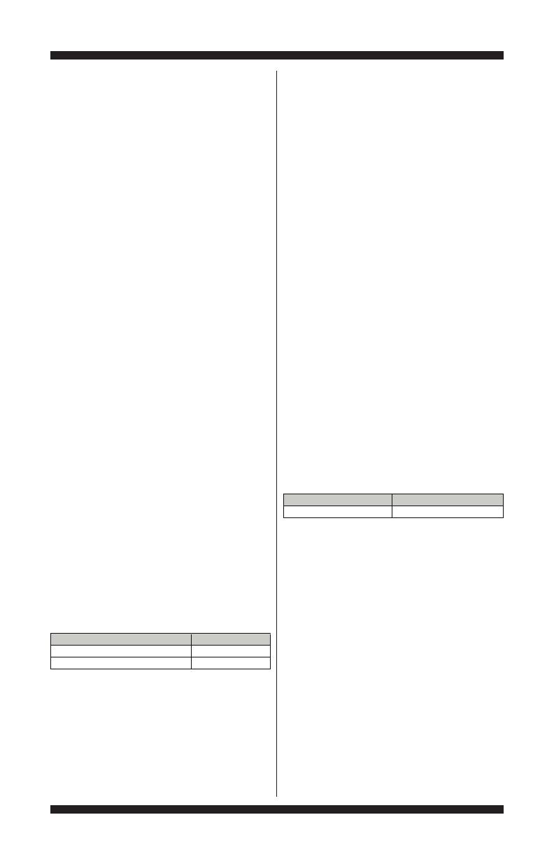
TEST #5: Temperature Thermistor
This test checks valves, main control,
temperature thermistor, and wiring.
1. Check the cold valve by performing Cold
Valve test under Manual Test Mode on page 9.
If cold water is being dispensed, proceed
to step 2.
If hot water is being dispensed, verify
proper hose connection.
2. Check the hot valve by performing Hot
Valve test under Manual Test Mode on page 9.
If hot water is being dispensed, proceed
to step 3.
If cold water is being dispensed, ensure
that household hot water is present.
3. Unplug washer or disconnect power.
4. Remove console to access main control.
5. Remove connector J3 from the main
control. With an ohmmeter, measure the
resistance of the temperature thermistor
between pins J3-9 and J3-10. Verify that the
approximate resistance, shown in the following
table, is within ambient temperature range.
(1)Fill (2)Wash (3)Rinse (4)Spin (5)Done

PAGE 17
FOR SERVICE TECHNICIAN’S USE ONLY
DO NOT REMOVE OR DESTROY
If the resistance is within the range shown
in the table, go to step 6.
If the resistance is infinite or close to zero,
replace the temperature thermistor assembly.
NOTE: Most thermistor errors are a result
of the resistor being out of range. If the
temperature thermistor malfunctions, the
washer will default to pre-programmed
wash settings.
6. If the thermistor is good, replace main
control and calibrate washer. Perform Automatic
Test to verify repair.
TEST #6: Water Level
This test checks the water level sensing
components. Depending on the model, the
washer will have either an on-board pressure
transducer or a separate pressure switch.
NOTE: Usually, if the pressure transducer or
pressure switch malfunctions, the washer will
generate a long fill, or long drain error.
1. Check the functionality of the pressure
transducer or pressure switch by running a
small load cycle. The valves should turn off
automatically after sensing the correct water level
in the tub. The following steps assume that this
step was unsuccessful.
2. Drain the tub until all water has been removed.
3. Unplug washer or disconnect power.
4. Remove console to access controls.
5. Check hose connection between the
pressure transducer or switch and the pressure
dome attached to the tub.
6. Check to ensure hose is routed correctly in
the lower cabinet and not pinched or crimped
by the back panel.
7. Verify there is no water, suds, or debris in
the hose or dome. Disconnect hose from main
control or pressure switch and blow into hose
to clear water, suds, or debris.
8. Check hose for leaks. Replace if needed.
9. If the preceding steps did not correct the
problem, go to step 10 if troubleshooting a
pressure switch, or step 11 if troubleshooting
an onboard pressure transducer.
10. Pressure Switch Only:
a. Remove the pressure hose from the switch.
b. Place the leads of an ohmmeter across
connector J4, pins 1 & 3 of the main control.
Blow into the pressure switch inlet. The
pressure switch contact should close and
show continuity.
If there is no continuity, check the harness
and connections between the pressure
switch and J4 on the main control. If OK,
replace the pressure switch.
If there is continuity, reconnect hose to
pressure switch and continue to step 11.
11. Replace the main control and calibrate
washer. Perform Automatic Test to verify repair.
TEST #7: Drain Pump
Perform the following checks if washer does
not drain.
NOTE: Refer to Figure 6, “Drain Pump Strip
Circuit” for tests and measurements.
IMPORTANT: Drain water from tub before
accessing bottom of washer.
1. Check for obstructions in the usual areas.
Clean and then perform step 2.
Approx. Resistance
F° C° (K
)
32 0 163
41 5 127
50 10 100
59 15 79
68 20 62
77 25 50
86 30 40
95 35 33
104 40 27
1134
52
2
122 50 18
131 55 15
140 60 12
149 65 10
A
pp
rox. Tem
p
erature
THERMISTOR RESISTANCE
Figure 6 - Drain Pump Strip Circuit
Main Control Shifter Assy
L1
Main Control
N
J16-3J7-1 J16-2
Pin 1
Pin 1
Pin 2
Pin 2 J7-3
K7
120VAC
Motor
Motor Resistance 14 to 25 ohms
Drain Pump Motor Relay
Drain Pump Motor

PAGE 18
FOR SERVICE TECHNICIAN’S USE ONLY
DO NOT REMOVE OR DESTROY
2. Check the drain pump and electrical
connections by performing the Drain Test under
Manual Test Mode on page 9. The following
steps assume that this step was unsuccessful.
3. Unplug washer or disconnect power.
4. Remove console to access main control.
5. Visually check that the J16 connector is
inserted all the way into the main control.
If visual check passes, go to step 6.
If connector is not inserted properly,
reconnect J16 and repeat step 2.
6. Remove connector J16 from main control.
With an ohmmeter, verify resistance values shown
below across the following J16 connector pinouts:
Resistance should be 14 –25 Ω.
If values are open or out of range, go to step 7.
If values are correct, go to step 11.
7. Tilt washer back to access drain pump.
Verify pump is free from obstructions.
8. Visually check the electrical connections
at the drain pump.
If visual check passes, go to step 9.
If connections are loose, reconnect the
electrical connections and repeat step 2.
9. With an ohmmeter, check harness for
continuity between the drain pump and main
control. See chart below.
If there is continuity, go to step 10.
If there is no continuity, replace the lower
machine harness and repeat step 2.
10. With an ohmmeter, measure the resistance
across the two pump terminals. Resistance
should be 14 –25 Ω.
If values are open or out of range, replace
the pump motor.
If the resistance at the pump motor is
correct, go to step 11.
11. If the preceding steps did not correct the
drain problem, replace the main control.
a. Unplug washer or disconnect power.
b. Replace the main control.
c. Reassemble all parts and panels.
d. Plug in washer or reconnect power. Calibrate
washer and perform Automatic Test to verify repair.
TEST #8: Lid Lock
Perform the following checks if the washer
does not lock (or unlock).
1. Perform the Lid Lock test under Manual
Test Mode on page 9. The following steps
assume that this step was unsuccessful.
2. Check lid lock mechanism for obstruction
or binding. Repair as necessary.
3. Unplug washer or disconnect power.
4. Remove console to access main control.
5. Visually check that the J15 connector is
inserted all the way into the main control.
If visual check passes, go to step 6.
If connector is not inserted properly,
reconnect J15 and repeat step 1.
6. Remove connector J15 from main control.
With an ohmmeter, verify lid lock resistance
values shown below across the following J15
connector pinouts:
If resistance values are good, go to step 7.
If switch measurements do not match the
values shown in the table for unlocked (or
locked) condition, a problem exists in the
lid lock. Replace the lid lock mechanism.
7. If the preceding steps did not correct the
lock problem, replace the main control.
a. Unplug washer or disconnect power.
b. Replace the main control.
c. Reassemble all parts and panels.
d. Plug in washer or reconnect power. Calibrate
washer and perform Automatic Test to verify repair.
Com
p
onent J16 Connector Pinout
Drain Pum
p
J16, 2 & 3
Main Control to Drain Pum
p
Drain Pum
p
Pin-1 to Main Control J16-3
Drain Pum
p
Pin-2 to Main Control J16-2
Component
Lock Switch
Solenoid
J15-1J15-3
4-51J3-51JhctiwS kcoL
2-51J3-51JhctiwS diL
Contacts
Measured
LID LOCK RESISTANCE
Lid Closed = 0 ohms
Lid Open = Open Circuit
85 to 155 ohms
Locked = 0 ohms
Unlocked = Open Circuit
Resistance
PAGE 19
FOR SERVICE TECHNICIAN’S USE ONLY
DO NOT REMOVE OR DESTROY
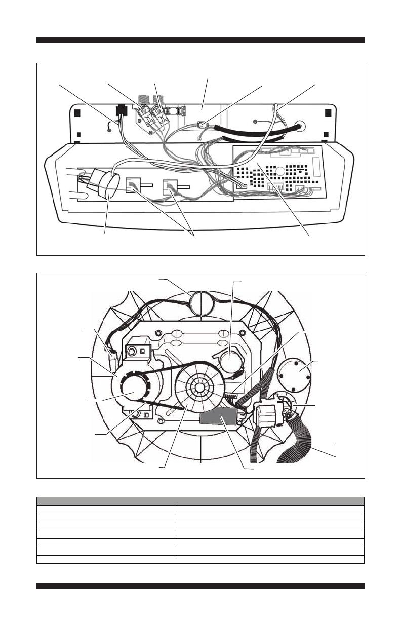
Component Locations – Console & Valves (Figure 7)
Specifications
Component Locations – Drive System & Drain Pump (Figure 8)
Main Control Board
AC Cord
Cold Water
Valve
Hot Water
Valve
Pressure
Hose
Pressure Switch
(select models)
Temperature
Thermistor
PSC Motor
Shifter Assy
Counterweight
(not on all
models)
Drain Pump
Drain Hose
Run Capacitor
Motor Pulley
Drive Belt
Shaft Pulley
PSC Motor
Connector
Shifter Assy
Connector
100-135 VAC:egatloV
57-63 Hz:ycneuqerF
12 Amps:spmA .xaM
15 Amp Instantaneous Type Fuse (Main Control):noitcetorP tiucriC
15-125 PSI:erusserP retaW
34 in. to 8 ft. (86 cm to 244 cm):thgieH niarD
40 - 115° F (4.5 - 46° C):egnaR erutarepmeT gnitarepO
WASHER SPECIFICATIONS
Rotary Switches
Coil Induction Loop
Dispenser

PAGE 20
FOR SERVICE TECHNICIAN’S USE ONLY
DO NOT REMOVE OR DESTROY
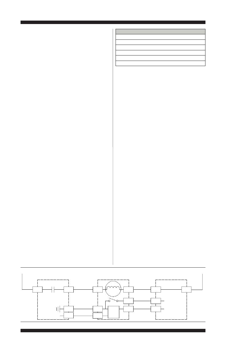
Wiring Diagram #1 (1/4 HP motor, separate pressure switch, 1 or 2 rotary switches)
IMPORTANT: Electrostatic discharge may cause damage to machine control electronics. See page 1 for
ESD information.
NOTE: Schematic shows shifter in SPIN position, lock switch open, and motor off.
Legend
Figure 9 - Wiring Diagram #1
1
2
L1
N
1
2
3
4
5
6
7
8
9
10
Hot
Cold
J3
J7
Water
Valves
890 to 1.3k ohms
Spin
Agitate
7
6
Optical
Sensor
Circuit
5
4
3
2
1
120Vac Motor
Shifter
Motor Resistance
2k to 3.5k ohms
2
1
Drain Pump
Motor Resistance
14 to 25 ohms
9
6
3
1
Motor Frame
Each Winding
5 to 9.5 ohms
PSC Motor
CW winding
CCW winding
Motor Run
Capacitor
1
2
3
4
5
J2
+13vdc
RPM input
Shifter Position
input
1
2
3
4
5
6
7
J16
4
3
2
Lock Switch
Lid Switch
Open when
lid is open
1
120Vac
Lock Switch Solenoid
85 to 155 ohms
120Vac Motor
Lid Lock
Lid
Switch
input
J15
Main Control
Red
White
Blue
Yellow
GND
Power
Cord
Blue
Red
White
Blue
Pink
Gray
Black
Brown
White/Blue
Tan
Lt Blue
White
Red
Orange
Green / Yellow
Yellow
3
A
B
Pressure
Switch
1
3
Pressure
Switch Input
J4
1
2
1
3
J11
3
4
5
6
Encoder
Switch
Inputs
Left
Rotary
Encoder
E2
Pressure switch contact
closes when water
reaches set level.
Rotary
Encoder
E1
3
1
Temperature
Input
Black
Black
Water Temp
Thermistor
10C (50F) 97k to 102k
25C (77F) 49k to 51k
40C (104F) 26k to 27.2k
Inductive
wire loop
Encoder positions viewed
from front of washer. Some
models feature E2 only.
1/4 HP
/