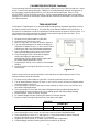
Detecto FH Series is a versatile and reliable floor scale designed to meet the demands of various weighing applications. Its low-profile design allows for easy loading and unloading, while the sturdy construction ensures accurate and consistent measurements. With its multiple connectivity options, the FH Series can be integrated into various systems for data collection and management. It's ideal for industrial, commercial, and retail settings, providing precise weighing solutions for a wide range of materials and products.
Detecto FH Series is a versatile and reliable floor scale designed to meet the demands of various weighing applications. Its low-profile design allows for easy loading and unloading, while the sturdy construction ensures accurate and consistent measurements. With its multiple connectivity options, the FH Series can be integrated into various systems for data collection and management. It's ideal for industrial, commercial, and retail settings, providing precise weighing solutions for a wide range of materials and products.


-
 1
1
-
 2
2
-
 3
3
-
 4
4
-
 5
5
-
 6
6
-
 7
7
-
 8
8
-
 9
9
-
 10
10


Detecto FH Series is a versatile and reliable floor scale designed to meet the demands of various weighing applications. Its low-profile design allows for easy loading and unloading, while the sturdy construction ensures accurate and consistent measurements. With its multiple connectivity options, the FH Series can be integrated into various systems for data collection and management. It's ideal for industrial, commercial, and retail settings, providing precise weighing solutions for a wide range of materials and products.
Ask a question and I''ll find the answer in the document
Finding information in a document is now easier with AI
Related papers
-
Detecto 760PS Series Owner's manual
-
-
-
-
-
-
-
-
-
Other documents
-
Cardinal Detecto 6855 Operating Instructions Manual
-
Milltronics MMI-2 User manual
-
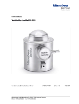 Minebea Intec PR 6221/12.5 t Installation guide
-
Mettler Toledo 7461 Installation guide
-
-
Cardinal Detecto Specification
-
-
-
-
Welch Allyn 6702W Series User manual
