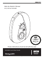
Mira Go Installation & User Guide
- Category
- Sanitary ware
- Type
- Installation & User Guide
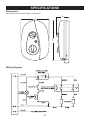
Mira Go is a high-quality electric shower that offers a range of features to enhance your showering experience. With separate controls for power selection and temperature/flow adjustment, you can easily customize your shower to your liking. The unique flow regulator stabilizes any temperature changes caused by water pressure fluctuations, ensuring a consistent and comfortable shower.
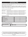
Mira Go is available in 8.5 kW, 9.5 kW, and 10.8 kW variants, making it suitable for a variety of domestic and light commercial applications. Its compact design and easy installation make it a great choice for both new and replacement installations.
Mira Go is a high-quality electric shower that offers a range of features to enhance your showering experience. With separate controls for power selection and temperature/flow adjustment, you can easily customize your shower to your liking. The unique flow regulator stabilizes any temperature changes caused by water pressure fluctuations, ensuring a consistent and comfortable shower.
Mira Go is available in 8.5 kW, 9.5 kW, and 10.8 kW variants, making it suitable for a variety of domestic and light commercial applications. Its compact design and easy installation make it a great choice for both new and replacement installations.


-
 1
1
-
 2
2
-
 3
3
-
 4
4
-
 5
5
-
 6
6
-
 7
7
-
 8
8
-
 9
9
-
 10
10
-
 11
11
-
 12
12
-
 13
13
-
 14
14
-
 15
15
-
 16
16
-
 17
17
-
 18
18
-
 19
19
-
 20
20
-
 21
21
-
 22
22
-
 23
23
-
 24
24
-
 25
25
-
 26
26
-
 27
27
-
 28
28


Mira Go Installation & User Guide
- Category
- Sanitary ware
- Type
- Installation & User Guide
Mira Go is a high-quality electric shower that offers a range of features to enhance your showering experience. With separate controls for power selection and temperature/flow adjustment, you can easily customize your shower to your liking. The unique flow regulator stabilizes any temperature changes caused by water pressure fluctuations, ensuring a consistent and comfortable shower.
Mira Go is available in 8.5 kW, 9.5 kW, and 10.8 kW variants, making it suitable for a variety of domestic and light commercial applications. Its compact design and easy installation make it a great choice for both new and replacement installations.
Ask a question and I''ll find the answer in the document
Finding information in a document is now easier with AI
Related papers
-
Mira Vista Installation & User Guide
-
-
-
-
-
-
-
-
Mira EXCEL User guide
-
Other documents
-
Kohler Mira Zest User manual
-
Caroma 2284848 Installation guide
-
-
Gainsborough 10.5 cse Installation guide
-
Redring Bright 9.5kW Multi-Connection Electric Shower User manual
-
-
-
Electrolux EYL10516WM User manual
-
Triton T90SR Installation And Operating Instructions Manual
-