Fiber Node Enclosure Installation Manual
Effective: February 2017

2
031-347-C0-001, Rev. A (02/2017)
Safety Notes
Alpha considers customer safety and satisfaction its most important priority. To reduce the risk of
injury or death and to ensure continual safe operation of this product, certain information is presented
differently in this manual. Alpha tries to adhere to ANSI Z535 and encourages special attention and
care to information presented in the following manner:
There may be multiple warnings associated with the call out. Example:
ATTENTION provides specic regulatory/code requirements that may affect the placement of
equipment and/or installation procedures.
ATTENTION:
NOTICE provides additional information to help complete a specic task or procedure.
NOTICE:
ELECTRICAL HAZARD WARNING provides electrical safety information to PREVENT
INJURY OR DEATH to the technician or user.
WARNING! ELECTRICAL HAZARD
FUMES HAZARD WARNING provides fumes safety information to PREVENT INJURY OR
DEATH to the technician or user.
WARNING! FUMES HAZARD
FIRE HAZARD WARNING provides ammability safety information to PREVENT INJURY OR
DEATH to the technician or user.
WARNING! FIRE HAZARD
This WARNING provides safety information for both Electrical AND Fire Hazards.
WARNING! ELECTRICAL AND FIRE HAZARD
CAUTION provides safety information intended to PREVENT DAMAGE to material or
equipment.
CAUTION!
GENERAL HAZARD WARNING provides safety information to PREVENT INJURY OR DEATH
to the technician or user.
WARNING! GENERAL HAZARD
LASER RADIATION WARNING provides safety information with respect to laser radiation and
optical bers.
WARNING! LASER RADIATION
MECHANICAL OR MOVING PARTS HAZARD
This symbol indicates a “mechanical or moving parts hazard” may exist in this area of the
product. Use caution whenever working in the area to prevent possible injury to the operator or
service personnel.

3
031-347-C0-001, Rev. A (02/2017)
The manual contains important safety information that must be followed during the installation and maintenance of the
equipment. Read all of the instructions before installing or operating the equipment and save this manual for future
reference.
Fiber Node Enclosure (FNE)
Enclosure Installation Manual
031-347-C0-001, Rev. A
Effective Date: February 2017
©
2017 by Alpha Technologies, Inc.
Disclaimer
Images contained in this manual are for illustrative purposes only. These images may not match your
installation.
Operator is cautioned to review the drawings and illustrations contained in this manual before
proceeding. If there are questions regarding the safe operation of this powering system, please
contact Alpha Technologies or your nearest Alpha representative.
Alpha shall not be held liable for any damage or injury involving its enclosures, power supplies,
generators, batteries or other hardware if used or operated in any manner or subject to any condition
not consistent with its intended purpose or is installed or operated in an unapproved manner or
improperly maintained.
Contact Information
Sales information and customer service in USA (7AM to 5PM, Pacic Time) ............................................. 1 800 322 5742
Complete technical support in USA (7AM to 5PM, Pacic Time or 24/7 emergency support) ....................1 800 863 3364
Sales information and technical support in Canada ....................................................................................1 888 462 7487
Website ........................................................................................................................................................www.alpha.com

4
031-347-C0-001, Rev. A (02/2017)
Contents
Introduction ............................................................................................................................................ 5
Important Safety Instructions ................................................................................................................. 6
1.0 The Fiber Node Enclosure (FNE) .................................................................................................... 7
1.1 Overview ..................................................................................................................................................... 7
1.2 Enclosure Specications ............................................................................................................................ 8
1.3 Site Selection ............................................................................................................................................... 9
1.4 Installing The Vault ...................................................................................................................................... 9
1.5 Grounding .................................................................................................................................................. 10
1.6 Installing The Enclosure On The Vault ...................................................................................................... 11
1.7 Populating The Enclosure ......................................................................................................................... 12
2.0 Optional Fan Kit ............................................................................................................................. 13
Figures and Tables
Fig. 1-1, Front View, Fiber Node Enclosure (FNE) ............................................................................................... 7
Fig. 1-2, Dimensioned View, Fiber Node Enclosure (FNE) .................................................................................. 8
Fig. 1-3, Sample Vault Installation ........................................................................................................................ 9
Fig. 1-4, Grounding System................................................................................................................................ 10
Fig. 1-5, Mounting Hole Spacing ........................................................................................................................ 10
Fig. 1-6, Mounting the Enclosure On the Vault ................................................................................................... 11
Fig. 1-7, Equipment Mounting Points, Enclosure Access Features .................................................................... 12
Fig. 2-1, Layout, Optional Lid-Mounted Fan Kit .................................................................................................. 13
Table 1-1, Specications, Fiber Node Enclosure (FNE) ....................................................................................... 8

5
031-347-C0-001, Rev. A (02/2017)
Audience
This guide is intended for experienced installers familiar with the mechanical and electrical requirements of Fiber Nodes
and qualied licensed installation personnel. Additionally, the installers must be familiar with enclosure installation as well
as underground vault installation and cable trenching.
Review the support documentation on the website to become familiar with the features and functions of the equipment
in this system before proceeding. Failure to install and/or use this equipment as instructed in the system documents can
result in damage to the equipment. This system is only serviceable by qualied personnel.
Trademark Information
Alpha
®
is a registered trademark of Alpha Technologies.
Revision History - P/N 031-347-C0-001
Version Date Description of Changes and New Features
A 02 / 2017 Initial Release of Document

6
031-347-C0-001, Rev. A (02/2017)
Important Safety Instructions
Review the drawings and illustrations contained in this manual before proceeding. If there are any questions regarding
the safe installation or operation of the system, contact Alpha Technologies or the nearest Alpha representative. Save this
document for future reference.
Alpha Technologies’ products are subject to change through continual improvement processes. Therefore, specications
or design layouts may vary slightly from the descriptions included in this manual. Updates to the manual are issued when
changes affect form, t or function.
ATTENTION:
To avoid injury:
• This enclosure and its associated hardware must be serviced only by authorized personnel.
• Enclosure must remain locked at all times, except when authorized service personnel are present.
• Remove all conductive jewelry or personal equipment prior to servicing.
• Read and follow all installation, equipment grounding, usage, and service instructions included in this manual.
• Use proper lifting techniques at all times.
General Safety Precautions
This enclosure and its associated hardware may contain equipment that has hazardous voltage or
currents.
CAUTION!
Enclosure, equipment or parts may be damaged or cause damage if used or installed improperly.
CAUTION!

7
031-347-C0-001, Rev. A (02/2017)
1.0 The Fiber Node Enclosure
1.1 Overview
The Fiber Node Enclosure (FNE) allows the exible conguration necessary to meet a wide range of applications,
including traditional and advanced Hybrid Fiber Coax (HFC), FTTx ber deep, Wi-Max networks, wireless outdoor base
stations, wireless IP access, and bulk power.
Cable Management System
The FNE is designed to accommodate customer-supplied nodes and passive splitters.
Cables enter and exit the enclosure via the polymer pedestal and trenched conduit.
Access panels on the side and rear of the enclosure allow technician access to the existing cabling or to add cabling as
future expansion demands.
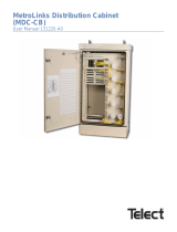
Fig. 1-1, Front View, Fiber Node Enclosure (FNE)
A
Node Mounting Bracket
B Bracket Alignment Indicator
C Optional Access Panels
D Mounting Brackets for Customer-Supplied Passive Splitters
E Optional Lid-Mounted Cooling Fan Kit (Alpha p/n 746-738-20-001)
D
C A
D D
A
B
D D
E
C
D
CC

8
031-347-C0-001, Rev. A (02/2017)
Fig. 1-2, Dimensioned view, Fiber Node Enclosure (FNE)
1.2 Enclosure Specications
Parameter
Value
Enclosure Dimensions, HxWxD (in/mm) 36 x 39 x 19 (914.4 x 990.6 x 482)
Weight (lb/kg) 60.5 / 27.4
Table 1-1, Specications, Fiber Node Enclosure (FNE)
1.0 The Fiber Node Enclosure, continued
36"
915mm
32"
813mm
34"
864mm
39"
991mm
19"
482mm
23"
584mm

9
031-347-C0-001, Rev. A (02/2017)
Considerations:
• Where possible, select a site above the 100-year ood plain, and away from houses.
• Place in a shaded location to minimize the effects of solar loading.
• Locate in an area where airow can be maximized.
• Avoid locating the enclosure where it is an obstruction and would inhibit visibility.
• Locate the enclosure away from sprinkler systems or other sources of forced water.
• Locate the enclosure out of the prevailing wind to minimize the buildup of snow or the accumulation
of wind-borne dust.
• Evaluate the soil conditions for suitability for the installation of the vault.
• Ensure cabling has been run and terminated at the site.
• Contact a cable locating service, the local utility, and adjacent building supervisors to ensure installation location
and cable routing does not interfere with existing utility connections.
1.3 Site Selection
1.0 The Fiber Node Enclosure, continued
1.4 Installing the Vault
Follow the vault manufacturer's instructions and local codes with respect to site excavation, trenching, ll materials and
creating cabling access ports in the vault. At this time, prepare the site for the installation of the enclosure grounding
system per the instructions in Section 1.5, Grounding.
A
Compacted Gravel for Drainage
B
Compacted Backll
C
Compacted Gravel to Grade
B
A
C
Fig. 1-3, Sample Vault Installation

10
031-347-C0-001, Rev. A (02/2017)
1.0 The Fiber Node Enclosure, continued
1
#6 bare copper wire from enclosure ground point to copper rod.
2
Connector: Burndy YGHP58C2W-2TN or equivalent, suitable for direct burial.
3
1/2" X 8' copper ground rod, driven into the ground at least two feet from the vault (or pad).
4
Vault below grade.
1.5 Grounding
Per the National Electrical Code (NEC), the grounding system for the FNE consists of a connection via a #6 bare
copper wire between the enclosure ground point and a single copper rod, 1/2" diameter x 8' long, driven into the
ground at least 2' from the vault (or pad). The copper wire is lugged on the end that attaches to the enclosure and is
connected to the ground rod by a connector that is suitable for direct burial.
Route the #6 bare copper wire from the enclosure through the vault (or pad) by means of the cable pass-through and
out to the ground rod.
Fig. 1-4, Grounding System
2
1
3
4

11
031-347-C0-001, Rev. A (02/2017)
1.0 The Fiber Node Enclosure, continued
1.6 Installing the Enclosure On the Vault
The enclosure is shipped from Alpha Technologies packed in a shipping carton.
Tools required:
• Torque wrench with 3/4" socket
• Ratchet set with extension
• Enclosure door key
• Vapor barrier material (if enclosure is being placed on a precast pad)
• Utility Knife
14"
356mm
32.7" / 830mm
Fig. 1-5, Mounting Hole Spacing
Fig. 1-6, Mounting the Enclosure On the Vault
Cable pass-through
If the vault is not supplied by Alpha Technologies, and does not have a pre-cut pass-through in
the lid, it will be necessary for the installer to cut a pass-through into the lid before installing the
enclosure.
NOTICE:
Procedure:
1. Unpack the enclosure.
2. If installing the enclosure on a precast pad, position the 25-year vapor barrier material over the pad, and make all
necessary cutouts. If the enclosure is being installed on a polymer vault, no vapor barrier material is needed.
3. Place the enclosure into position on the vault lid.
4. Route any pre-run cables into the enclosure and secure the enclosure to the ber vault lid by means of four (4)
customer supplied 3/8"-16 stainless steel bolts, at washers and lock washers. Tighten to a torque value of 19 to 20
lb-ft.
5. If vapor barrier material is used, trim the vapor barrier material around the perimeter of the enclosure with a utility
knife.

12
031-347-C0-001, Rev. A (02/2017)
A
Remove node mounting bracket from rear wall of enclosure. Use wrench and 7/16" socket
to remove 2 stainless-steel bolts from each of the upper and lower mounting anges.
B
Attach node to bracket per manufacturer's instructions.
C
Reattach bracket to mounting anges.
D
Access Panels (2 side, 2 rear) are used to facilitate installation of cabling.
E
As needed, install passive splitters per manufacturer's instructions.
F
Removable lid, 4 x 1/4-20 nuts; requires 7/16" wrench.
1.7 Populating the Enclosure
The node mounting bracket [B] accommodates a variety of nodes. The FNE is also congured with horizontal and vertical
mounting brackets [E] allowing the addition of passive splitters per the requirements of future system expansion. The
enclosure lid is removeable and, if need be, can be removed to facilitate installing and splicing the node.
Four sliding access panels [D] are located on the rear and side of the enclosure. To use a panel, sufciently loosen (do
not remove) the four 1/4-20 nuts at the corners of the panel to allow the panel to slide toward the front of for the side
access panels and to the closest side for the rear access panels the enclosure.
The FNE is congured with a removable lid [F] to facilitate installing and splicing the node. The lid is held in place by 4
(four) 1/4-20 nuts located in the inside corners of the enclosure. To remove the lid, unplug the fan kit from the cable plant,
and with a 7/16" wrench remove the 4 (four) 1/4-20 nuts from the inside corners of the lid, lift the lid off and set aside. To
reattach the lid, reverse the above procedure.
Follow the manufacturer's instructions with regard to node and/or passive splitter installation, connection, conguration,
start-up and validation.
Fig. 1-7, Equipment Mounting Points, Enclosure Access Features
1.0 The Fiber Node Enclosure, continued
B
C
A
D
D
E
F
E
D
D

13
031-347-C0-001, Rev. A (02/2017)
Fig. 2-1 Layout, Optional Lid-Mounted Fan Kit
2.0 Optional Fan Kit
The FNE can be congured with an optional factory-installed lid-mounted cooling fan kit (Alpha p/n 746-738-20-001). The
kit is comprised of two fans mounted inside the lid and powered by AC voltage provided by the cable plant. In the event
the kit requires service or is added after the initial commissioning of the system, follow the appropriate procedure below.
Initial Installation
1. Use a wrench with a 7/16" socket to remove the
4 (four) 1/4-20 Keps nuts and remove the lid.
2. Set the lid upside down on its roof.
3. Set the fan panel on the lid over the installed
studs.
4. Use a wrench with a 1/4" socket to install the 3
(three) 6-32 onto the studs in the lid.
5. Connect the customer-supplied coaxial cable to
the fan kit.
6. Replace and secure the lid on the enclosure.
7. Connect the coaxial cable from the fan kit to the
cable plant.
8. Secure the enclosure.
Lid
MECHANICAL OR MOVING PARTS HAZARD
Keep hands clear of the fan openings. The cooling fans are thermostatically-controlled and may start when power
is applied.
To reduce the risk of electrical shock, connect the customer-supplied coaxial cable to the fan panel rst, then
connect the cable to the cable plant.
WARNING! ELECTRICAL HAZARD
Removal and Replacement
1. Disconnect the fan kit from the cable plant.
2. Use a wrench with a 7/16" socket to remove the 4
(four) 1/4-20 Keps nuts and remove the lid.
3. Use a wrench with a 1/4" socket to remove the 3
(three) 6-32 Keps nuts from the studs in the lid and
remove the fan kit.
4. Remove the customer-supplied coaxial cable from
the existing fan kit.
5. Install the replacement fan kit into the lid.
6. Connect the coaxial cable to the replacement unit.
7. Replace the lid on the enclosure.
8. Connect the coaxial cable from the fan kit to the
cable plant.
9. Secure the enclosure.
Fan kit
Power Cable

Alpha Technologies
Alpha reserves the right to change specications without notice.
Alpha is a registered trademark of Alpha Technologies.
For more information visit www.alpha.com
© 2017 Alpha Technologies Inc. All Rights Reserved.
031-347-C0-001 Rev. A (02/2017)
Worldwide Corporate Ofces
North America
Tel: +1 360 647 2360
Fax: +1 360 671 4936
Europe
Tel: +49 9122 79889 0
Fax: +49 9122 79889 21
Latin America
Tel: +561 792.9651
Fax: +561 792.7157
Asia Pacic
Tel: +852 2736.8663
Fax: +852 2199.7988
/