Emerson Liebert GXT3 On-Line RT 10000VA User manual
- Type
- User manual

AC Power
For Business-Critical Continuity™
Liebert
®
GXT3
™
208V, 5000-10,000VA, 6000RTL630
User Manual


i
TABLE OF CONTENTS
1.0 INTRODUCTION . . . . . . . . . . . . . . . . . . . . . . . . . . . . . . . . . . . . . . . . . . . . . . . . . . . . . . . . . .4
2.0 SYSTEM DESCRIPTION . . . . . . . . . . . . . . . . . . . . . . . . . . . . . . . . . . . . . . . . . . . . . . . . . . . .5
2.1 Transient Voltage Surge Suppression (TVSS) and EMI/RFI Filters. . . . . . . . . . . . . . . . . . . . 5
2.2 Rectifier/Power Factor Correction (PFC) Circuit . . . . . . . . . . . . . . . . . . . . . . . . . . . . . . . . . . . 5
2.3 Inverter . . . . . . . . . . . . . . . . . . . . . . . . . . . . . . . . . . . . . . . . . . . . . . . . . . . . . . . . . . . . . . . . . . . . 5
2.4 Battery Charger . . . . . . . . . . . . . . . . . . . . . . . . . . . . . . . . . . . . . . . . . . . . . . . . . . . . . . . . . . . . . 5
2.5 DC-to-DC Converter . . . . . . . . . . . . . . . . . . . . . . . . . . . . . . . . . . . . . . . . . . . . . . . . . . . . . . . . . . 5
2.6 Battery . . . . . . . . . . . . . . . . . . . . . . . . . . . . . . . . . . . . . . . . . . . . . . . . . . . . . . . . . . . . . . . . . . . . 6
2.7 Dynamic Bypass . . . . . . . . . . . . . . . . . . . . . . . . . . . . . . . . . . . . . . . . . . . . . . . . . . . . . . . . . . . . . 6
3.0 MAJOR COMPONENTS . . . . . . . . . . . . . . . . . . . . . . . . . . . . . . . . . . . . . . . . . . . . . . . . . . . .7
3.1 Main Frame and Electronics . . . . . . . . . . . . . . . . . . . . . . . . . . . . . . . . . . . . . . . . . . . . . . . . . . . 7
3.2 Removable Power Distribution Box. . . . . . . . . . . . . . . . . . . . . . . . . . . . . . . . . . . . . . . . . . . . . . 9
3.3 Internal Battery Packs. . . . . . . . . . . . . . . . . . . . . . . . . . . . . . . . . . . . . . . . . . . . . . . . . . . . . . . 10
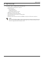
4.0 WHAT’S INCLUDED . . . . . . . . . . . . . . . . . . . . . . . . . . . . . . . . . . . . . . . . . . . . . . . . . . . . . . 11
5.0 INSTALLATION AND CONFIGURATION . . . . . . . . . . . . . . . . . . . . . . . . . . . . . . . . . . . . . . . . .12
5.1 Install the Main Cabinet . . . . . . . . . . . . . . . . . . . . . . . . . . . . . . . . . . . . . . . . . . . . . . . . . . . . . 12
5.1.1 Tower UPS Installation . . . . . . . . . . . . . . . . . . . . . . . . . . . . . . . . . . . . . . . . . . . . . . . . . . . . . . . 12
5.1.2 Rack-Mount UPS Installation . . . . . . . . . . . . . . . . . . . . . . . . . . . . . . . . . . . . . . . . . . . . . . . . . . 13
5.1.3 Installing the Adjustable Rack-Mount Kit—Sold Separately . . . . . . . . . . . . . . . . . . . . . . . . . 13
5.2 External Battery Cabinet Installation . . . . . . . . . . . . . . . . . . . . . . . . . . . . . . . . . . . . . . . . . . 16
5.3 Connect Input/Output Power. . . . . . . . . . . . . . . . . . . . . . . . . . . . . . . . . . . . . . . . . . . . . . . . . . 17
5.3.1 Remove the Power Distribution Box from 5000 and 6000VA Models . . . . . . . . . . . . . . . . . . . 17
5.3.2 Remove the Power Distribution Cover from 8000 and 10,000VA Models . . . . . . . . . . . . . . . . 18
5.3.3 Install the Power Distribution Box on 5000 and 6000VA Models . . . . . . . . . . . . . . . . . . . . . . 18
5.3.4 Install the Power Distribution Box on 8000 and 10,000VA Models . . . . . . . . . . . . . . . . . . . . 19
5.3.5 Distribution Box Electrical Connections . . . . . . . . . . . . . . . . . . . . . . . . . . . . . . . . . . . . . . . . . . 19
5.4 IT Power System Configuration—Liebert
®
GXT3-6000RTL630
™
Only . . . . . . . . . . . . . . . . 21
6.0 CONFIGURATION PROGRAM . . . . . . . . . . . . . . . . . . . . . . . . . . . . . . . . . . . . . . . . . . . . . . .22
6.1 Configuration Program Features . . . . . . . . . . . . . . . . . . . . . . . . . . . . . . . . . . . . . . . . . . . . . . 22
6.1.1 What You Will Need . . . . . . . . . . . . . . . . . . . . . . . . . . . . . . . . . . . . . . . . . . . . . . . . . . . . . . . . . . 22
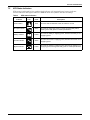
7.0 CONTROLS AND INDICATORS. . . . . . . . . . . . . . . . . . . . . . . . . . . . . . . . . . . . . . . . . . . . . . .23
7.1 ON/Alarm Silence/Manual Battery Test Button . . . . . . . . . . . . . . . . . . . . . . . . . . . . . . . . . . 23
7.2 Standby/Manual Bypass Button . . . . . . . . . . . . . . . . . . . . . . . . . . . . . . . . . . . . . . . . . . . . . . . 23
7.3 Load Level Indicators (4 Green, 1 Amber) . . . . . . . . . . . . . . . . . . . . . . . . . . . . . . . . . . . . . . . 24
7.4 Battery Level Indicators (5 Green) . . . . . . . . . . . . . . . . . . . . . . . . . . . . . . . . . . . . . . . . . . . . . 24
7.5 UPS Status Indicators . . . . . . . . . . . . . . . . . . . . . . . . . . . . . . . . . . . . . . . . . . . . . . . . . . . . . . . 25
8.0 OPERATION . . . . . . . . . . . . . . . . . . . . . . . . . . . . . . . . . . . . . . . . . . . . . . . . . . . . . . . . . . .26
8.1 Startup Checklist for the Liebert GXT3
™
. . . . . . . . . . . . . . . . . . . . . . . . . . . . . . . . . . . . . . . . 26
8.2 Initial Startup and Electrical Checks . . . . . . . . . . . . . . . . . . . . . . . . . . . . . . . . . . . . . . . . . . . 26
8.3 Manual Battery Test . . . . . . . . . . . . . . . . . . . . . . . . . . . . . . . . . . . . . . . . . . . . . . . . . . . . . . . . 27

ii
8.4 Put the Liebert
®
GXT3
™
in Manual Bypass. . . . . . . . . . . . . . . . . . . . . . . . . . . . . . . . . . . . . . 27
8.5 Shut Down the Liebert GXT3 . . . . . . . . . . . . . . . . . . . . . . . . . . . . . . . . . . . . . . . . . . . . . . . . . 27
8.6 Disconnecting Input Power from the Liebert GXT3. . . . . . . . . . . . . . . . . . . . . . . . . . . . . . . . 27
8.7 Maintenance Bypass . . . . . . . . . . . . . . . . . . . . . . . . . . . . . . . . . . . . . . . . . . . . . . . . . . . . . . . . 27
9.0 COMMUNICATION . . . . . . . . . . . . . . . . . . . . . . . . . . . . . . . . . . . . . . . . . . . . . . . . . . . . . . .28
9.1 Communication Interface Port . . . . . . . . . . . . . . . . . . . . . . . . . . . . . . . . . . . . . . . . . . . . . . . . 28
9.2 Terminal Block . . . . . . . . . . . . . . . . . . . . . . . . . . . . . . . . . . . . . . . . . . . . . . . . . . . . . . . . . . . . . 28
9.2.1 Any-Mode Shutdown . . . . . . . . . . . . . . . . . . . . . . . . . . . . . . . . . . . . . . . . . . . . . . . . . . . . . . . . . 28
9.2.2 Battery Mode Shutdown . . . . . . . . . . . . . . . . . . . . . . . . . . . . . . . . . . . . . . . . . . . . . . . . . . . . . . 28
9.2.3 On Battery . . . . . . . . . . . . . . . . . . . . . . . . . . . . . . . . . . . . . . . . . . . . . . . . . . . . . . . . . . . . . . . . . 29
9.2.4 Low Battery . . . . . . . . . . . . . . . . . . . . . . . . . . . . . . . . . . . . . . . . . . . . . . . . . . . . . . . . . . . . . . . . 29
9.3 Liebert IntelliSlot
®
Communication Cards. . . . . . . . . . . . . . . . . . . . . . . . . . . . . . . . . . . . . . . 29
9.3.1 Liebert
®
MultiLink
®
. . . . . . . . . . . . . . . . . . . . . . . . . . . . . . . . . . . . . . . . . . . . . . . . . . . . . . . . . . 30
9.4 Remote Emergency Power Off . . . . . . . . . . . . . . . . . . . . . . . . . . . . . . . . . . . . . . . . . . . . . . . . . 30
10.0 MAINTENANCE . . . . . . . . . . . . . . . . . . . . . . . . . . . . . . . . . . . . . . . . . . . . . . . . . . . . . . . . .31
10.1 Replacing the Internal Battery Pack. . . . . . . . . . . . . . . . . . . . . . . . . . . . . . . . . . . . . . . . . . . . 31
10.1.1 Battery Replacement Procedures . . . . . . . . . . . . . . . . . . . . . . . . . . . . . . . . . . . . . . . . . . . . . . . 31
10.2 Battery Charging . . . . . . . . . . . . . . . . . . . . . . . . . . . . . . . . . . . . . . . . . . . . . . . . . . . . . . . . . . . 32
10.3 Precautions . . . . . . . . . . . . . . . . . . . . . . . . . . . . . . . . . . . . . . . . . . . . . . . . . . . . . . . . . . . . . . . . 32
10.4 Checking UPS Status . . . . . . . . . . . . . . . . . . . . . . . . . . . . . . . . . . . . . . . . . . . . . . . . . . . . . . . . 33
10.5 Checking UPS Functions . . . . . . . . . . . . . . . . . . . . . . . . . . . . . . . . . . . . . . . . . . . . . . . . . . . . . 33
10.6 Replacing the Power Module on 8000 and 10,000VA models . . . . . . . . . . . . . . . . . . . . . . . . 33
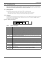
11.0 TROUBLESHOOTING . . . . . . . . . . . . . . . . . . . . . . . . . . . . . . . . . . . . . . . . . . . . . . . . . . . . .35
11.1 UPS Symptoms. . . . . . . . . . . . . . . . . . . . . . . . . . . . . . . . . . . . . . . . . . . . . . . . . . . . . . . . . . . . . 35
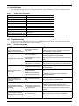
11.1.1 Indicators . . . . . . . . . . . . . . . . . . . . . . . . . . . . . . . . . . . . . . . . . . . . . . . . . . . . . . . . . . . . . . . . . . 35
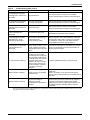
11.1.2 Audible Alarm. . . . . . . . . . . . . . . . . . . . . . . . . . . . . . . . . . . . . . . . . . . . . . . . . . . . . . . . . . . . . . . 36
11.2 Troubleshooting . . . . . . . . . . . . . . . . . . . . . . . . . . . . . . . . . . . . . . . . . . . . . . . . . . . . . . . . . . . . 36
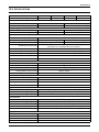
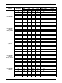
12.0 SPECIFICATIONS . . . . . . . . . . . . . . . . . . . . . . . . . . . . . . . . . . . . . . . . . . . . . . . . . . . . . . . .38
12.1 Auto-Learning Battery Run Times . . . . . . . . . . . . . . . . . . . . . . . . . . . . . . . . . . . . . . . . . . . . . 44

iii
FIGURES
Figure 1 Liebert GXT3 front view—rack-mount and tower configurations . . . . . . . . . . . . . . . . . . . . . . . . . . 7
Figure 2 Liebert GXT3 5000VA and 6000VA rear view . . . . . . . . . . . . . . . . . . . . . . . . . . . . . . . . . . . . . . . . . 7
Figure 3 Input power hardwire boxes—5000 and 6000VA models . . . . . . . . . . . . . . . . . . . . . . . . . . . . . . . . . 7
Figure 4 Liebert® GXT3-6000RTL630
™
, rear view . . . . . . . . . . . . . . . . . . . . . . . . . . . . . . . . . . . . . . . . . . . . . 8
Figure 5 Liebert GXT3 8000VA and 10,000VA rear view . . . . . . . . . . . . . . . . . . . . . . . . . . . . . . . . . . . . . . . . 8
Figure 6 Power distribution models for 5000VA and 6000VA models of Liebert® GXT3
™
. . . . . . . . . . . . . . 9
Figure 7 Power distribution models for 8000VA and 10,000VA models of Liebert® GXT3
™
. . . . . . . . . . . 10
Figure 8 Internal battery pack features . . . . . . . . . . . . . . . . . . . . . . . . . . . . . . . . . . . . . . . . . . . . . . . . . . . . . 10
Figure 9 Support bases . . . . . . . . . . . . . . . . . . . . . . . . . . . . . . . . . . . . . . . . . . . . . . . . . . . . . . . . . . . . . . . . . . 12
Figure 10 Remove the front plastic bezel cover . . . . . . . . . . . . . . . . . . . . . . . . . . . . . . . . . . . . . . . . . . . . . . . . 12
Figure 11 Rotate the operation and display panel . . . . . . . . . . . . . . . . . . . . . . . . . . . . . . . . . . . . . . . . . . . . . . 13
Figure 12 External battery cabinets connected to 6000VA Liebert GXT3 . . . . . . . . . . . . . . . . . . . . . . . . . . . 16
Figure 13 Power distribution box removal from 5000 and 6000VA models . . . . . . . . . . . . . . . . . . . . . . . . . . 17
Figure 14 Power distribution box removal from 8000 and 10,000VA models . . . . . . . . . . . . . . . . . . . . . . . . 18
Figure 15 Distribution box electrical connections diagram . . . . . . . . . . . . . . . . . . . . . . . . . . . . . . . . . . . . . . . 19
Figure 16 Terminal block connections . . . . . . . . . . . . . . . . . . . . . . . . . . . . . . . . . . . . . . . . . . . . . . . . . . . . . . . 20
Figure 17 Remove cover from IT Power System Connectors compartment . . . . . . . . . . . . . . . . . . . . . . . . . . 21
Figure 18 Liebert
®
GXT3
™
control panel . . . . . . . . . . . . . . . . . . . . . . . . . . . . . . . . . . . . . . . . . . . . . . . . . . . . . 23
Figure 19 Load level indicators . . . . . . . . . . . . . . . . . . . . . . . . . . . . . . . . . . . . . . . . . . . . . . . . . . . . . . . . . . . . . 24
Figure 20 Battery level indicators. . . . . . . . . . . . . . . . . . . . . . . . . . . . . . . . . . . . . . . . . . . . . . . . . . . . . . . . . . . 24
Figure 21 Terminal block communication pin layout . . . . . . . . . . . . . . . . . . . . . . . . . . . . . . . . . . . . . . . . . . . 28
Figure 22 Removing the front plastic bezel cover and battery door . . . . . . . . . . . . . . . . . . . . . . . . . . . . . . . . 31
Figure 23 Disconnecting the battery plug and battery receptacle (front view) . . . . . . . . . . . . . . . . . . . . . . . 31
Figure 24 Pulling out the battery packs . . . . . . . . . . . . . . . . . . . . . . . . . . . . . . . . . . . . . . . . . . . . . . . . . . . . . . 32
Figure 25 Removing power module from Liebert
®
GXT3
™
8000 and 10,000VA models . . . . . . . . . . . . . . . . 34
Figure 26 Battery level indicator . . . . . . . . . . . . . . . . . . . . . . . . . . . . . . . . . . . . . . . . . . . . . . . . . . . . . . . . . . . 35
TABLES
Table 1 Branch circuit breaker ratings . . . . . . . . . . . . . . . . . . . . . . . . . . . . . . . . . . . . . . . . . . . . . . . . . . . . . 19
Table 2 Electrical specifications . . . . . . . . . . . . . . . . . . . . . . . . . . . . . . . . . . . . . . . . . . . . . . . . . . . . . . . . . . 20
Table 3 UPS status indicators . . . . . . . . . . . . . . . . . . . . . . . . . . . . . . . . . . . . . . . . . . . . . . . . . . . . . . . . . . . . 25
Table 4 Indicator descriptions . . . . . . . . . . . . . . . . . . . . . . . . . . . . . . . . . . . . . . . . . . . . . . . . . . . . . . . . . . . . 35
Table 5 Audible alarm description . . . . . . . . . . . . . . . . . . . . . . . . . . . . . . . . . . . . . . . . . . . . . . . . . . . . . . . . 36
Table 6 Troubleshooting table . . . . . . . . . . . . . . . . . . . . . . . . . . . . . . . . . . . . . . . . . . . . . . . . . . . . . . . . . . . . 36
Table 7 UPS specifications—5000, 6000, 8000 and 10,000 models . . . . . . . . . . . . . . . . . . . . . . . . . . . . . . . 38
Table 8 UPS specifications—Liebert
®
GXT3-6000RTL630
™
. . . . . . . . . . . . . . . . . . . . . . . . . . . . . . . . . . . . 39
Table 9 Operating temperature parameters. . . . . . . . . . . . . . . . . . . . . . . . . . . . . . . . . . . . . . . . . . . . . . . . . 40
Table 10 Internal battery cabinet specifications . . . . . . . . . . . . . . . . . . . . . . . . . . . . . . . . . . . . . . . . . . . . . . 40
Table 11 External battery cabinet specifications . . . . . . . . . . . . . . . . . . . . . . . . . . . . . . . . . . . . . . . . . . . . . . 41
Table 12 Power distribution specifications: GXT3-5000RT208, GXT3-6000RT208 and
GXT3-6000RTL630 . . . . . . . . . . . . . . . . . . . . . . . . . . . . . . . . . . . . . . . . . . . . . . . . . . . . . . . . . . . . . . 41
Table 13 Power distribution box specifications for GXT3-8000RT208 and GXT3-10000RT208 . . . . . . . . . 42
Table 14 Battery run time, minutes . . . . . . . . . . . . . . . . . . . . . . . . . . . . . . . . . . . . . . . . . . . . . . . . . . . . . . . . 43

iv

1
IMPORTANT SAFETY INSTRUCTIONS
SAVE THESE INSTRUCTIONS
This manual contains important safety instructions. Read all safety and operating instructions before
operating the uninterruptible power system (UPS). Adhere to all warnings on the unit and in this
manual. Follow all operating and user instructions. This equipment can be operated by individuals
without previous training.
This product is designed for commercial/industrial use only. It is not intended for use with life support
and other designated “critical” devices. Maximum load must not exceed that shown on the UPS rating
label. The UPS is designed for data processing equipment. If uncertain, consult your dealer or local
Emerson Network Power representative.
This UPS is designed for use on a properly grounded (earthed), 100/200, 110/220, 115/230,
120/208,120/240 or 127/220VAC, 50 or 60Hz supply. The factory default setting is 120/208VAC, 60Hz.
Installation instructions and warning notices are in this manual.
The Liebert
®
GXT3
™
208VAC 5000 - 10000 is designed for use with a four-wire input (L1, L2, N, G).
The Liebert GXT3-6000RTL630
™
is designed be used with a three-wire, two-phase utility source
(L1, L2, G).
!
WARNING
The battery can present a risk of electrical shock and high short circuit current. The following
precautions should be observed when replacing the battery pack:
• Wear rubber gloves and boots
• Remove rings, watches and other metal objects.
• Use tools with insulated handles.
• Do not lay tools or other metal objects on the batteries.
• If the battery kit is damaged in any way or shows signs of leakage, contact your local Emer-
son representative immediately.
• Do not dispose of batteries in a fire. The batteries may explode.
• Handle, transport and recycle batteries in accordance with local regulations.
!
WARNING
Although the Liebert GXT3 has been designed and manufactured to ensure personal safety,
improper use can result in electrical shock or fire. To ensure safety, observe the following
precautions:
• Turn Off and unplug the Liebert GXT3 before cleaning it.
• Clean the UPS with a dry cloth. Do not use liquid or aerosol cleaners.
• Never block or insert any objects into the ventilation holes or other openings of the UPS.
• Do not place the Liebert GXT3 power cord where it might be damaged.

2
ELECTROMAGNETIC COMPATIBILITY—The Liebert
®
GXT3
™
complies with the limits for a
Class A digital device, pursuant to Part 15 of FCC rules.
Operation is subject to the following conditions:
• This device may not cause harmful interference.
• This device must accept any interference received, including interference that may cause unde-
sired operation. Operating this device in a residential area is likely to cause harmful interference
that users must correct at their own expense.
The Liebert GXT3 series complies with the requirements of EMC Directive 2004/108/EC and the pub-
lished technical standards. Continued compliance requires installation in accordance with these
instructions and use of accessories approved by Emerson.
NOTICE
This is a product for restricted sales distribution to informed partners. Installation
restrictions or additional measures may be needed to prevent radio interference.
Operate the UPS in an indoor environment only in an ambient temperature range of 0-40°C
(32-104°F). Install it in a clean environment, free from moisture, flammable liquids, gases and corro-
sive substances.
The Liebert GXT3-5000RT208
™
, Liebert GXT3-6000RT208
™
and the Liebert GXT3-6000RTL630
™
contain no user-serviceable parts except the internal battery pack. The Liebert GXT3-10000RT208
™
and the Liebert GXT3-8000RT208
™
contain no user-serviceable parts except the internal battery pack
and the Power Module. The UPS On/Off push buttons do not electrically isolate internal parts. Under
no circumstances attempt to gain access internally due to the risk of electric shock or burn.
Do not continue to use the UPS if the front panel indications are not in accordance with these operat-
ing instructions or the UPS performance alters in use. Refer all faults to your dealer.
Servicing of batteries should be performed or supervised by personnel knowledgeable of batteries and
the required precautions. Keep unauthorized personnel away from the batteries. Keep unauthorized
personnel away from the batteries. Proper disposal of batteries is required. Refer to your local laws
and regulations for disposal requirements.
Never block or insert any object into the ventilation holes or other openings.
DO NOT CONNECT equipment that could overload the UPS or demand DC current from the UPS,
for example: electric drills, vacuum cleaners, laser printers, hair dryers or any appliance using half-
wave rectification.
Storing magnetic media on top of the UPS may result in data loss or corruption.
Turn Off and isolate the UPS before cleaning it. Use only a soft cloth, never liquid or aerosol cleaners.
Information for the Protection of the Environment
UPS SERVICING—This UPS makes use of components dangerous for the environment (electronic
cards, electronic components). The components removed must be taken to specialized collection and
disposal centers.

3
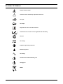
GLOSSARY OF SYMBOLS
Risk of electrical shock
Indicates caution followed by important instructions
AC input
AC output
Requests the user to consult the manual
Indicates the unit contains a valve-regulated lead acid battery
Recycle
DC voltage
Equipment grounding conductor
Bonded to ground
AC voltage
ON/Alarm Silence/Manual Battery Test
OFF/Bypass
WEEE
!
i
PbH2SO4
-
+
R

Introduction
4
1.0 INTRODUCTION
Congratulations on your choice of the Liebert
®
GXT3
™
uninterruptible power system (UPS). The
Liebert GXT3 comes in nominal power ratings of 5000VA, 6000VA, 8000VA and 10,000VA. It is
designed to provide conditioned power to microcomputers and other sensitive electronic equipment.
When it is generated, alternating current is clean and stable. However, during transmission and dis-
tribution it is subject to voltage sags, spikes and complete power failure that may interrupt computer
operations, cause data loss and even damage equipment. The Liebert GXT3 protects equipment from
these disturbances.
The Liebert GXT3 is a compact, on-line UPS. An on-line UPS continuously conditions and regulates
its output voltage, whether utility power is present or not. It supplies connected equipment with
clean, sinewave power. Sensitive electronic equipment operates best from sinewave power.
For ease of use, the Liebert GXT3 features a light-emitting diode (LED) display to indicate both load
percentage and battery capacity. It also provides self-diagnostic tests, a combination ON/Alarm
Silence/Manual Battery Test button, a Standby/Manual Bypass button and a configuration program.
The Liebert GXT3 has a Liebert IntelliSlot
®
port for communication between the UPS and a network
server or other computer systems. This port provides detailed operating information including
voltages, currents and alarm status to the host system when used in conjunction with Liebert
MultiLink
®
. Liebert MultiLink can also remotely control UPS operation.

System Description
5
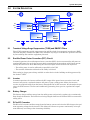
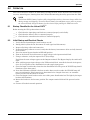
2.0 SYSTEM DESCRIPTION
2.1 Transient Voltage Surge Suppression (TVSS) and EMI/RFI Filters
These UPS components provide surge protection and filter both electromagnetic interference (EMI)
and radio frequency interference (RFI). They minimize any surges or interference present in the util-
ity line and keep the sensitive equipment protected.
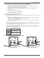
2.2 Rectifier/Power Factor Correction (PFC) Circuit
In normal operation, the rectifier/power factor correction (PFC) circuit converts utility AC power to
regulated DC power for use by the inverter while ensuring that the waveshape of the input current
used by the UPS is near ideal. Extracting this sinewave input current achieves two objectives:
• The utility power is used as efficiently as possible by the UPS.
• The amount of distortion reflected on the utility is reduced.
This results in cleaner power being available to other devices in the building not being protected by
the Liebert
®
GXT3
™
.
2.3 Inverter
In normal operation, the inverter utilizes the DC output of the power factor correction circuit and
inverts it into precise, regulated sinewave AC power. Upon a utility power failure, the inverter
receives its required energy from the battery through the DC-to-DC converter. In both modes of oper-
ation, the UPS inverter is on-line and continuously generating clean, precise, regulated AC output
power.
2.4 Battery Charger
The battery charger utilizes energy from the utility power and precisely regulates it to continuously
float charge the batteries. The batteries are being charged whenever the Liebert GXT3 is connected to
utility power.
2.5 DC-to-DC Converter
The DC-to-DC converter utilizes energy from the battery system and raises the DC voltage to the opti-
mum operating voltage for the inverter. This allows the inverter to operate continuously at its opti-
mum efficiency and voltage, thus increasing reliability.
Input
Output
Inverter
Battery
Rectifier/PFC
DC-to-DC
Converter
TVSS &
EMI/RFI
Filters
L1
G G
Static
Bypass
L2
N
L1
L2
N
Battery
Charger

System Description
6
2.6 Battery
The Liebert
®
GXT3
™
utilizes valve-regulated, nonspillable, lead acid batteries. To maintain battery
design life, operate the UPS in an ambient temperature of 15°C to 25°C (59°F to 77°F). Optional
external battery cabinets are available to extend battery run times. For run times, see Table 14.
2.7 Dynamic Bypass
The Liebert GXT3 provides an alternate path for utility power to the connected load in the unlikely
event of a UPS malfunction. Should the UPS have an overload, overtemperature or any other UPS
failure condition, the UPS automatically transfers the connected load to bypass. Bypass operation is
indicated by an audible alarm and illuminated amber Bypass LED (other LEDs may be illuminated to
indicate the diagnosed problem). To manually transfer the connected load from the inverter to bypass,
press the Standby/Manual Bypass button once and hold it for about 2 seconds.
NOTE
The bypass power path does NOT protect the connected equipment from disturbances
in the utility supply.

Major Components
7
3.0 MAJOR COMPONENTS
The Liebert
®
GXT3
™
is composed of three major assemblies to provide easier handling, installation
and versatility.
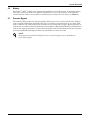
3.1 Main Frame and Electronics
All models of the Liebert GXT3 are shipped without the internal batteries installed. Power distribu-
tion varies by model and rating.
• Liebert GXT3 5000 and 6000VA models ship with a basic hardwire distribution box attached and
ready to be connected to the load (see Figure 2).
• Liebert GXT3RTL630
™
ships with a power distribution box attached (see (Figure 4).
• Liebert GXT3 8000 and 10,000VA models with a cover plate installed over connections for any of
several optional power distribution boxes (see Figure 5).
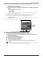
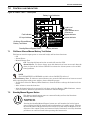
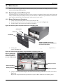
Figure 1 Liebert GXT3 front view—rack-mount and tower configurations
Figure 2 Liebert GXT3 5000VA and 6000VA rear view
Figure 3 Input power hardwire boxes—5000 and 6000VA models
NOTE
Hardwire and hardwire/receptacle boxes that include a manual bypass switch permit AC
power to continue to flow from the utility input to the load while the box is removed from the
UPS. For details, refer to 3.2 - Removable Power Distribution Box.
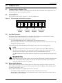
Status Indicators
and Controls
Lower Bezel and
Battery Access
Door
Upper Bezel
External Battery
Connector
Liebert
IntelliSlot
Port
USB Port
Terminal Block
Communication
Input Breaker
Knockouts for Hardwired
Power Input
REPO
PD2-HDWR
5000 and 6000VA models
PD2-HDWR-MBS - 5000
and 6000VA models
Maintenance
Bypass Breaker
Input Breaker
Input
Breaker

Major Components
8
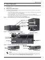
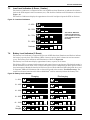
Figure 4 Liebert
®
GXT3-6000RTL630
™
, rear view
Figure 5 Liebert GXT3 8000VA and 10,000VA rear view
External
Battery
Connector
Liebert
IntelliSlot
Port
USB Port
Terminal Block
Communication
Maintenance
Bypass Breaker
REPO Connection
Block
Output Breaker
for L6-30R #4
Input Breaker
for L6-30P #1
1
2
3
4
5
Output Breaker for
L6-20R #2 and #3
Output Breaker
for L6-30R #5
IT Power
System
Access
Cover
External Battery
Connector
Liebert
IntelliSlot
Port
USB Port
Terminal Block
Communication
Maintenance
Bypass
Switch
Knockouts
for Hardwired
Power Input
REPO Connection Block
Input
Breaker
Switch
Output
Breaker
Switch
Cover for Power
Distribution Box
Connections

Major Components
9
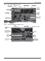
3.2 Removable Power Distribution Box
The UPS is shipped with a power distribution pack installed. This box contains the UPS input circuit
breaker.
Figure 6 Power distribution models for 5000VA and 6000VA models of Liebert
®
GXT3
™
PD2-001
Receptacles: four 5-20; one
L14-30; one L6-30R
PD2-002
Receptacles: two 5-20R; two L6-20R
PD2-003
receptacles: four 5-20R; two L6-30
PD2-005
Receptacles: four L5-20R; two L6-30R
PD2-004
Receptacles: four L5-20R; two L5-30R
PD2-006
Receptacles: four L6-20R
L14-30 Input
Power Connector
Input Power
Breaker
Maintenance
Bypass Breaker
Output Power Breakers
for Pigtails
Push Button Output
Power Breakers for Two
L5-20 Receptacles
(second push button
breaker obscured)
PD2-001 shown as example;
similar features on other distribution
boxes arranged differently

Major Components
10
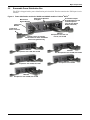
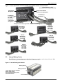
Figure 7 Power distribution models for 8000VA and 10,000VA models of Liebert
®
GXT3
™
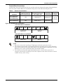
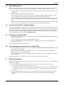
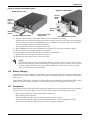
3.3 Internal Battery Packs
The UPS has two internal battery packs behind a battery access door on the front of the unit. Each
internal battery pack is fitted with a connector to link to the UPS.
Figure 8 Internal battery pack features
PD2-102
Receptacles:
four L6-20R
four 5-20R
PD2-103
Receptacles:
four L6-30R
four 5-20R
PD2-104
Receptacles:
four 5-20R
two L6-30R
two L6-20R
PD2-105
Receptacles:
four 5-20R
two L5-30R
two L5-20R
PD2-106
Receptacles:
four L6-20R
four L5-20R
Output Circuit Breaker
Switch for L6-30R Pigtail #1
5-20R Output
Receptacles
5-20R Output
Receptacles
Push Button
Circuit Breakers
for 5-20R
Receptacles
L6-30ROutput
Receptacles
PD2-101
Receptacles: two L6-30; eight 5-20R
p;
similar features on other
distribution boxes arranged differently
Output Circuit Breaker
Switch for L6-30R Pigtail #2
2
1
Battery Connector
Front of Battery Pack
Liebert GXT3 8000 and 10,000VA
battery packs shown;
5000 and 6000VA battery packs
have same features
Battery Handle

What’s Included
11
4.0 WHAT’S INCLUDED
The Liebert
®
GXT3
™
is shipped with the following items:
• Terminal Block Communication terminals
• Compact disc with:
• Liebert MultiLink
®
• Configuration program
• User manual (electronic version)
• USB cable, one; 2m (6-1/2 ft.) long
• Rack handles with mounting hardware
• Power Distribution Box, installed on Liebert GXT3
• Plastic tower set, one
• Warnings, safety instructions booklet and WEEE recycling sheet (ISO 14001 compliance)
NOTE
The Liebert GXT3 External Battery Cabinet shipping package includes one battery cabinet, two
spacers for the 5000 and 6000VA models and four spacers for the 8000 and 10000VA models
for tower configuration and one DC power cable.

Installation and Configuration
12
5.0 INSTALLATION AND CONFIGURATION
Do NOT attempt to start the UPS, turn on any circuit breaker or energize the input power until
instructed to do so in 8.2 - Initial Startup and Electrical Checks.
Visually inspect the UPS for shipping damage. Report any damage to the carrier and your local dealer
or Emerson representative.
Install the Liebert
®
GXT3
™
indoors in a controlled environment, where it cannot be accidentally
turned off. Place it where air flows unrestricted around the unit. The installation location must be
free of water, flammable liquids, gases, corrosives and conductive contaminants. Maintain a mini-
mum clearance of 100mm (4 inches) in the front and rear of the UPS. Maintain an ambient tempera-
ture range of 0 to 40°C (32 -104°F).
5.1 Install the Main Cabinet
The Liebert GXT3 may be installed in either a tower configuration or in a rack, depending on avail-
able space and use considerations. Determine the type of installation and follow the appropriate
instructions in either 5.1.1 - Tower UPS Installation or 5.1.2 - Rack-Mount UPS Installation.
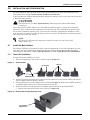
5.1.1 Tower UPS Installation
To install the Liebert GXT3 as a tower:
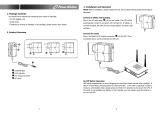
1. Take the support bases out of the accessories bag (see Figure 9).
Figure 9 Support bases
2. If optional Liebert external battery cabinets will be connected to the Liebert GXT3, take out the
spacers shipped with the battery cabinet.
3. Connect the spacers and the support bases as shown in Figure 9. Each Liebert GXT3 needs two
assembled support bases, one in the front and one in the rear.
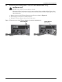
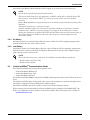
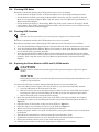
4. Adjust the direction of the operation and display panel and logo on the Liebert GXT3.
a. Remove the front plastic bezel cover as shown in Figure 10.
Figure 10 Remove the front plastic bezel cover
!
CAUTION
The UPS is heavy (see 12.0 - Specifications). Take proper precautions when lifting
or moving it.
NOTE
UPS operation in sustained temperatures outside the range of 15-25°C (59°-77°F)
reduces battery life.
Support Bases
Spacers
Connectors
Front Plastic
Bezel Cover

Installation and Configuration
13
b. Pull the operation and display panel gently, rotate it 90 degrees clockwise and snap it back
into position, as shown in Figure 11.
Figure 11 Rotate the operation and display panel
c. Pull the logo on the front plastic bezel cover gently, rotate it 90 degrees clockwise and snap it
back into position. The rotated front plastic bezel cover is shown in Figure 11.
d. Replace the front plastic bezel cover on the Liebert
®
GXT3
™
. At this point, the UPS operation
and display panel and logo have been rotated 90 degrees clockwise, which provides upright
viewing for users.
5. Place the Liebert GXT3 and any battery cabinets on the support bases. Each Liebert GXT3 needs
two support assemblies, as shown in the lower half of Figure 1.
5.1.2 Rack-Mount UPS Installation
When using the Liebert GXT3 in a rack, the UPS must be supported by a slide kit, fixed rails or a
shelf.
When using the optional Adjustable Rack Mount Kit, you will use the following instructions. The fig-
ures accompanying 5.1.3 - Installing the Adjustable Rack-Mount Kit—Sold Separately shows
the positioning of the rack-mounting brackets. Emerson recommends taking the internal batteries out
of the UPS during rack installation. This will make the UPS cabinet lighter and easier to handle.
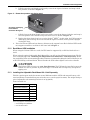
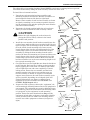
5.1.3 Installing the Adjustable Rack-Mount Kit—Sold Separately
This kit contains parts needed to mount several different models of UPS and external battery cabi-
nets into EIA310-D standard four-post racks that are 18-32" deep (457-813mm). The weight limit per
pair of adjustable rack-mounting brackets is 91 kg (200lb).
Parts included are:
Tools needed for installation are:
• one Phillips screwdriver
• one 7mm wrench
!
CAUTION
The Liebert GXT3 is heavy; see 12.0 - Specifications. The UPS must be installed as near the
bottom of a rack as possible. If placed too high, it can make the rack top-heavy and prone to
tipping over.
Item Quantity
Rear bracket members 2
Front bracket members 2
Inner bracket members 2
M4 machine screws 16
M4 locking hex nuts 8
M5 machine screws 8
Operation and Display
Panel Rotated
Clockwise 90 Degrees

Installation and Configuration
14
The adjustable rack-mounting brackets (Part#: RMKIT18-32) feature retaining latches to prevent
users from inadvertently sliding the UPS or battery cabinet out of the rack.
To install the rack mount brackets:
1. Unpack two rack-mounting bracket assemblies and
mounting hardware from this kit. Bracket assemblies are
interchangeable between left-hand or right-hand.
Remove inner member of each bracket assembly as shown
at right by extending it to its outermost position, depress-
ing the retaining latch and then pulling the inner member
out of the bracket assembly.
2. Determine the height position inside the rack enclosure
where you want to mount the UPS or battery cabinet.
3. Install the rear member of each bracket assembly into the
rack enclosure with two M5 screws provided in this kit (see
figure at right). The return flanges on the bracket assembly
fit to the inside of rack mounting rails. Insert screws
loosely (finger-tight) into the top and bottom holes of the
return flange on the rear member. Extend the bracket
assembly by sliding the front member forward until it
touches the front rack mounting rail. Insert two M5 screws
loosely (finger-tight) into the top and bottom holes of the
return flange on each front member. Make sure that the
bracket assemblies are at the same mounting height on all
four (4) rack mounting rails.
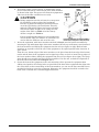
4. Get eight M4 screws and eight M4 nuts from the hardware
pack in this kit. Each nut has a locking, nylon insert that
begins gripping the screw when it is halfway tight. Make
sure to tighten the nut and screw completely to ensure
locking action. Fasten the rear member and the front
member together using four screws and four nuts per
bracket assembly as shown in at right. For maximum
support, insert fasteners for each bracket assembly as far
apart as possible, depending on rack depth, while still
joining both members (see figures at right). Check
alignment of bracket assemblies and TIGHTEN ALL
SCREWS FROM Steps 2 and 3.
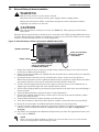
5. Prepare the UPS or battery cabinet (the “equipment”) for
rack mounting by following instructions in the equipment’s
user manual. The equipment may require additional parts
to be added or parts to be removed for rack mounting. After
it is prepared, lay the equipment in rack-mounting
position. Fasten the inner members from Step 1 to the
equipment on both sides as shown at right with eight M4
screws provided in the kit. Make sure retaining latch is
near the rear of the equipment as shown (see figure at
right).
!
CAUTION
Reduce the risk of tipping the rack enclosure by
placing the UPS or battery cabinet in the lowest
possible rack position.
Return
flanges
Inner
members
Front
members
Retaining
Latches
M5 screws
M5 screws
Front rack
mounting rails
457mm
(18")
rack
depth
M4 nuts
M4 nuts
M4
screws
813mm
(32") rack
depth
M4 nuts
M4 nuts
M4
screws
UPS or battery
cabinet
Front
M4 screws
M4 screws
Retaining latch
Page is loading ...
Page is loading ...
Page is loading ...
Page is loading ...
Page is loading ...
Page is loading ...
Page is loading ...
Page is loading ...
Page is loading ...
Page is loading ...
Page is loading ...
Page is loading ...
Page is loading ...
Page is loading ...
Page is loading ...
Page is loading ...
Page is loading ...
Page is loading ...
Page is loading ...
Page is loading ...
Page is loading ...
Page is loading ...
Page is loading ...
Page is loading ...
Page is loading ...
Page is loading ...
Page is loading ...
Page is loading ...
Page is loading ...
Page is loading ...
Page is loading ...
Page is loading ...
-
 1
1
-
 2
2
-
 3
3
-
 4
4
-
 5
5
-
 6
6
-
 7
7
-
 8
8
-
 9
9
-
 10
10
-
 11
11
-
 12
12
-
 13
13
-
 14
14
-
 15
15
-
 16
16
-
 17
17
-
 18
18
-
 19
19
-
 20
20
-
 21
21
-
 22
22
-
 23
23
-
 24
24
-
 25
25
-
 26
26
-
 27
27
-
 28
28
-
 29
29
-
 30
30
-
 31
31
-
 32
32
-
 33
33
-
 34
34
-
 35
35
-
 36
36
-
 37
37
-
 38
38
-
 39
39
-
 40
40
-
 41
41
-
 42
42
-
 43
43
-
 44
44
-
 45
45
-
 46
46
-
 47
47
-
 48
48
-
 49
49
-
 50
50
-
 51
51
-
 52
52


Emerson Liebert GXT3 On-Line RT 10000VA User manual
- Type
- User manual
Ask a question and I''ll find the answer in the document
Finding information in a document is now easier with AI
Related papers
-
Emerson Liebert GXT3 Series User manual
-
-
Emerson GXT3-5000RT208 User manual
-
SolaHD MultiLINK Owner's manual
-
-
-
-
-
-
Other documents
-
Liebert GXT3-5000RT230 User manual
-
-
-
Avocent GXT3-3000RT120 Datasheet
-
-
-
APC SURT011 User manual
-
-
 PowerWalker DC SecureAdapter 12V Owner's manual
-
