quickstart guide
DVPHD - V-Panel™ Integration
www.crestron.com
888.273.7876 201.767.3400
Specifications subject to
change without notice.
DVPHD - V-Panel Integration
QUICKSTART DOC. 6987C (2027661) 09.11
In addition to the DGE Digital Graphics Engine, Crestron
®
V-Panel™ displays are also compatible
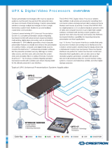
with the award winning DVPHD High Definition Digital Video Processors, enabling the display of up
to eight simultaneous video windows along with high definition touch screen graphics and annotation.
The DVPHD supports high definition video and computer signals from a wide variety of digital and
analog sources. Its DVI output connects to the V12 or V15 via a DigitalMedia™ CAT transmitter or
DM
®
switcher, enabling cable runs up to 200 feet (~61 meters).
The maximum number of inputs/windows available on the V-Panel will depend on the DVPHD model
used:
DVPHD-DUAL-R Up to two video inputs
DVPHD-QUAD-R Up to four video inputs
DVPHD-PRO-R Up to eight video inputs
1
Introduction
2
Requirements
The following hardware is required for DVPHD - V-Panel integration:
NOTE: DVPHD - V-Panel integration requires the following minimum firmware versions:
• DVPHD 3.001.0104 or later
• V-Panel 3.001.0062 or later
3
Setup
The following diagram shows the hardware connections for DVPHD - V-Panel integration.
A. Hardware
B. Software
1. Download the appropriate DVPHD - V-Panel Integration SIMPL Windows demo program and Crestron
VisionTools
®
(VT Pro-e
®
) demo project for your V-Panel (V12 or V15) from the Crestron Web site
(www.crestron.com/exampleprograms). Load the SIMPL Windows program into the control system and load
the VT Pro-e project into the DVPHD. This will calibrate the touch from the V-Panel to the DVPHD.
2. Routing the touch data must be done via the control system. The demo project shows this in detail. Calibration
must be done using the demo project (or via integrating the demo project into the user project).
DVPHD, DM transmitter and control system connect to Ethernet network.
NOTE: DVPHD, DM device and control system must be on the same subnet.
NOTE: As the DVPHD has no audio, no audio will be supplied to the V-Panel, unless
breakaway audio is inserted via a DM switcher.
DVPHD
DM
Transmitter*
V-Panel
DVI DM
Ethernet
Control
System
* Examples of DM transmitters are the DM-TX-100 or DM-MD8X8, among others.
Contact Crestron for more information.
NOTE: Calibration will be stored in the V-Panel. This is different from other touch screens used with the DVPHD,
where the calibration is stored in the DVPHD.
1
3. Use the Device Discovery Tool in Crestron Toolbox™ to find the IP addresses of the DVPHD and the V-Panel
(and optionally, the DM transmitter).
a. In the Device Discovery Tool, select the DVPHD. The “System Info” window will be displayed. Click the
arrow on the right side of the “IP Table” section. In the “IP Table Setup” window that opens, enter the IP
address of the control system and the IP ID of the DVPHD, as specified in the SIMPL Windows program.
b. Do the same for the V-Panel, selecting your model (V12 or V15) from the Device Discovery Tool,
then clicking the arrow to the right side of the IP Table section and entering the IP address of the control
system, along with the IP ID of the V-Panel, as specified in the SIMPL Windows program. (Optionally,
you can follow similar steps for the DM transmitter as well.)
4. To verify connections, check the “IP Table Setup” window for each device. The listing under the Status field
should say “online”.
Refer to additional diagrams in Section 4.
You can also create your own user project in VT Pro-e. This can be a separate project or it can be integrated into the
demo project to keep the calibration process. If you create a custom project that is not integrated into the demo project,
make sure to set the appropriate resolution for your V-Panel. In the “Project Properties” window of the project, use the
Page size dropdown list to select the appropriate resolution (800 x 600 for the V12 and 1280 x 768 for the V15).
NOTE: The HID Extender programming from the demo program must be copied into the SIMPL Windows user
program. (The calibration information is not necessary.)
NOTE: The DVPHD must have a DHDC-RGBO-R output card installed.
• Crestron control system
• DVPHD with a DHDC-RGBO-R output card installed
• DM switcher or transmitter
• V-Panel display
NOTE: After it is powered on, the system may take up to a minute to come online.
NOTE: The term “DM Cable” in this document refers to DM CAT cable (e.g.,
DM-CBL-NP or DM-CBL-P). Minimum DM CAT cable length is 15 feet (~4.6 meters).


