Vivanco UNIVERSAL SWITCHMODE AC TO DC MAINS ADAPTERS WITH USB CHARGING FUNCTION User guide

Category
Supplementary music equipment
Type
User guide

This manual is also suitable for

1
1
2
Novation
A division of Focusrite Audio Engineering Ltd.
Windsor House,
Turnpike Road,
Cressex Business Park,
High Wycombe,
Bucks,
HP12 3FX.
United Kingdom
Tel: +44 1494 462246
Fax: +44 1494 459920
e-mail: sales@novationmusic.com
Web: http://www.novationmusic.com
Trademarks
The Novation trademark is owned by Focusrite Audio Engineering Ltd. All other brand,
product and company names and any other registered names or trade marks mentioned in
this manual belong to their respective owners.
Disclaimer
Novation has taken all possible steps to ensure that the information given here is both
correct and complete. In no event can Novation accept any liability or responsibility for
any loss or damage to the owner of the equipment, any third party, or any equipment
which may result from use of this manual or the equipment which it describes. The
information provided in this document may be modified at any time without prior warning.
Specifications and appearance may differ from those listed and illustrated.
IMPORTANT SAFETY
INSTRUCTIONS
1. Read these instructions.
2. Keep these instructions.
3. Heed all warnings.
4. Follow all instructions.
5. Do not use this apparatus with water.
6. Clean only with dry cloth.
7. Do not install near any heat sources such as radiators, heat registers, stoves, or other
apparatus (including amplifiers) that produce heat.
8. Do not defeat the safety purpose of the polarized or grounding-type plug. A polarized
plug has two blades with one wider than the other. A grounding type plug has two blades
and a third grounding prong. The wide blade or the third prong are provided for your safety.
If the provided plug does not fit into your outlet, consult an electrician for replacement of
the obsolete outlet.
9. Protect the power cord from being walked on or pinched particularly at plugs,
convenience receptacles, and the point where they exit from the apparatus.
10. Only use attachments/accessories specified by the manufacturer.
11.
Use only with the cart, stand, tripod, bracket, or table specified by the
manufacturer, or sold with the apparatus. When a cart is used, use
caution when moving the cart/apparatus combination to avoid injury
from tip-over.
12. Unplug this apparatus during lightning storms or when unused for long periods of time.
13. Refer all servicing to qualified service personnel. Servicing is required when the
apparatus has been damaged in any way, such as power-supply cord or plug is damaged,
liquid has been spilled or objects have fallen into the apparatus, the apparatus has been
exposed to rain or moisture, does not operate normally, or has been dropped.
14. No naked flames, such as lighted candles, should be placed on the apparatus.
WARNING: Excessive sound pressure levels from earphones and headphones can cause
hearing loss.
WARNING: This equipment must only be connected to USB 1.1 or 2.0 type ports.
CAUTION: TO REDUCE THE RISK OF
ELECTRIC SHOCK, DO NOT REMOVE
COVER (OR BACK). NO USER-SERVICABLE
PARTS INSIDE. REFER SERVICING TO
QUALIFIED SERVICE PERSONNEL.
The lightning flash with arrowhead symbol within an equilateral triangle is
intended to alert the user to the presence of uninsulated “dangerous voltage”
within the product’s enclosure that may be of sufcient magnitude to constitute
the risk of electric shock to persons.
The exclamation point within an equilateral triangle is intended to alert the user
to the presence of important operating and maintenance (servicing) instructions
in the literature accompanying the appliance.
WARNING: TO REDUCE THE RISK OF FIRE OR ELECTRIC SHOCK, DO NOT EXPOSE
THIS APPARATUS TO RAIN OR MOISTURE.
ENVIRONMENTAL
D E C L AR AT I O N
Compliance Information Statement: Declaration of Compliance procedure
Product Identification: Novation Bass Station II keyboard
Responsible party: American Music and Sound
Address: 4325 Executive Drive,
Suite 300
Southaven,
MS 38672
Telephone: 800-431-2609
This device complies with part 15 of the FCC Rules. Operation is subject to the following
two conditions: (1) This device may not cause harmful interference, and (2) this device
must accept any interference received, including interference that may cause undesired
operation.
For USA
To the User:
1. Do not modify this unit! This product, when installed as indicated in the instructions
contained in this manual, meets FCC requirements. Modifications not expressly
approved by Novation may void your authority, granted by the FCC, to use this product.
2. Important: This product satisfies FCC regulations when high quality shielded USB
cables with integral ferrite are used to connect with other equipment. Failure to use high
quality shielded USB cables with integral ferrite or to follow the installation instructions
within this manual may cause magnetic interference with appliances such as radios and
televisions and void your FCC authorization to use this product in the USA.
3. Note: This equipment has been tested and found to comply with the limits for a Class
B digital device, pursuant to part 15 of the FCC Rules. These limits are designed to
provide reasonable protection against harmful interference in a residential installation.
This equipment generates, uses and can radiate radio frequency energy and, if not
installed and used in accordance with the instructions, may cause harmful interference
to radio communications. However, there is no guarantee that interference will not occur
in a particular installation. If this equipment does cause harmful interference to radio
or television reception, which can be determined by turning the equipment off and on,
the user is encouraged to try to correct the interference by one or more of the following
measures:
• Reorient or relocate the receiving antenna.
• Increase the separation between the equipment and receiver.
Connect the equipment into an outlet on a circuit different from that to which the
receiver
is connected.
• Consult the dealer or an experienced radio/TV technician for help.
For Canada
To the User:
This Class B digital apparatus complies with Canadian ICES-003.
Cet appareil numérique de la classe B est conforme à la norme NMB-003 du Canada.
RoHS Notice
Novation has conformed and product conforms, where applicable, to the European
Union’s Directive 2002/95/EC on Restrictions of Hazardous Substances (RoHS) as
well as the following sections of California law which refer to RoHS, namely sections
25214.10, 25214.10.2, and 58012, Health and Safety Code; Section 42475.2, Public
Resources Code.
CAUTION:
The normal operation of this product may be affected by a strong electrostatic discharge
(ESD). In the event of this happening, simply reset the unit by removing and then
replugging the USB cable. Normal operation should return.
COPYRIGHT AND LEGAL
NOTICES
Novation is a registered trade mark of Focusrite Audio Engineering Limited.
Bass Station II is a trade mark of Focusrite Audio Engineering Limited.
2013 © Focusrite Audio Engineering Limited. All rights reserved.
3
CONTENTS
IMPORTANT SAFETY
INSTRUCTIONS ..............................................................2
ENVIRONMENTAL
DECLARATION...............................................................2
For USA .................................................................2
For Canada ..............................................................2
COPYRIGHT AND LEGAL NOTICES............................................2
INTRODUCTION..............................................................4
Key Features .............................................................4
About This Manual ........................................................4
What’s In The Box.........................................................4
Registering your Bass Station II .............................................4
Power Requirements ......................................................4
Hardware Overview .......................................................5
GETTING STARTED...........................................................7
Loading Patches ..........................................................7
Saving Patches ...........................................................7
Basic Operation – sound modication .......................................7
The LED display ....................................................7
The Filter knob......................................................7
Pitch and Mod wheels . . . . . . . . . . . . . . . . . . . . . . . . . . . . . . . . . . . . . . . . . . . . . . .7
Octave Shift........................................................7
Transpose .........................................................8
On-Key functions ...................................................8
Local control .......................................................8
SYNTHESIS TUTORIAL........................................................8
Pitch ..............................................................8
Tone ..............................................................8
Volume ............................................................8
The Oscillators And Mixer ............................................9
Sine Waves ........................................................9
Triangle Waves .....................................................9
Sawtooth Waves....................................................9
Square / Pulse Waves ...............................................9
Noise .............................................................9
Ring Modulation ....................................................9
The Filter ........................................................ 10
Envelopes And Amplifier ........................................... 10
Attack Time .......................................................11
Decay Time .......................................................11
Sustain Level ......................................................11
Release Time......................................................11
LFOs.............................................................11
Summary .........................................................11
SIMPLIFIED BASS STATION II BLOCK DIAGRAM . . . . . . . . . . . . . . . . . . . . . . . . . . . . . . .12
BASS STATION II IN DETAIL ..................................................12
The Oscillator Section ....................................................12
Waveform........................................................ 12
Pitch ............................................................ 12
Modulation....................................................... 12
Pulse Width...................................................... 13
Oscillator Sync ................................................... 13
The Sub Oscillator ................................................ 13
The Mixer Section ........................................................13
The Filter Section ........................................................13
Filter type ........................................................ 13
Frequency ....................................................... 14
Resonance....................................................... 14
Filter modulation .................................................. 14
Overdrive ........................................................ 14
The Envelopes Section ...................................................14
Portamento .............................................................15
The Effects Section ......................................................15
The LFO Section.........................................................15
LFO 1:........................................................... 15
LFO 2: .......................................................... 15
LFO Waveforms .................................................. 16
LFO Speed ...................................................... 16
LFO Delay ....................................................... 16
LFO Speed/Sync ................................................. 16
LFO Keysync ..................................................... 16
LFO Slew ........................................................ 16
The Arpeggiator Section ..................................................16
Arp Swing ....................................................... 17
The Sequencer ..........................................................17
Record .......................................................... 17
Play ............................................................. 17
SEQ Retrig ...................................................... 17
On-key Functions ........................................................17
APPENDIX ..................................................................19
Importing Patches via SysEx...............................................19
Sync values table ........................................................19
Init Patch – parameter table ...............................................20
Synth settings saved on power-off ..........................................20
Synth settings not saved on power-off ......................................20
MIDI parameters list ......................................................21
MIDI implementation table.................................................21
4
INTRODUCTION
Thank you for purchasing this Bass Station II digitally-controlled analogue synthesizer.
Based on the classic 1990s Novation Bass Station synth, it combines traditional analogue
waveform generation and processing with the power and fl exibility of digital control, plus a
set of effects and presets for the 21st century.
NOTE: Bass Station II is capable of generating audio with a large dynamic range, the
extremes of which can cause damage to loudspeakers or other components, and also to
your hearing!
Key Features
Classic analogue waveform generation
Two multi-waveform oscillators plus separate sub oscillator
Analogue signal path – fi lters, envelopes, modulation
Traditional “single function” style rotary controls
LP/BP/HP fi lters with variable slope
Separate dual LFO section
Ring Modulator (inputs: Oscs 1 and 2)
Versatile 32-step arpeggiator with wide range of patterns
32-step sequencer with four memories
Portamento with dedicated time control
Pre-loaded with 64 brand new Killer Patches
Memory for 64 additional User Patches
Pitch and Mod wheels
25-note velocity-sensitive keyboard with aftertouch
-5/+4 octave keyboard shift
Key transpose function
On-Key functions – use the keyboard to adjust non-performance sound parameters
MIDI input and output
LED display for patch selection, parameter adjustment, octave settings, etc.
External DC input (for supplied AC PSU)
Class-compliant USB port (no drivers required), for alternative DC power, patch
dump and MIDI
External audio input to mixer section
Headphone output
Sustain pedal socket
Kensington Security Slot
About This Manual
We’ve tried to make this manual as helpful as possible for all types of user, and this
inevitably means that more experienced users will want to skip over certain parts of it, while
relative novices will want to avoid certain parts of it until they’re confi dent they’ve mastered
the basics.
However, there are a few general points that are useful to know about before you continue
reading this manual. We’ve adopted some graphical conventions within the text, which we
hope all types of user will fi nd helpful in navigating through the information to fi nd what they
need to know quickly:
Abbreviations, conventions, etc.
Where top panel controls or rear panel connectors are referred to, we’ve used a number
thus:
1
to cross-reference to the top panel diagram, and thus:
1
1
to cross-reference to
the rear panel diagram. (See page 5 and page 6).
We’ve used BOLD TEXT (or Bold Text) to name top panel controls or rear panel
connectors; we’ve made a point of using exactly the same names as appear on the Bass
Station II. We’ve used SEVEN-SEGMENT DIGITS to denote numbers that appear on the top
panel LED display.
Tips
These do what it says on the tin: we include bits of advice, relevant to the
topic being discussed that should simplify setting up Impulse to do what
you want. It’s not mandatory that you follow them, but generally they
should make life easier.
These are additions to the text that will be of interest to the more
advanced user and can generally be avoided by the novice. They are
intended to provide a clari cation or explanation of a particular area of
operation.
What’s In The Box
Your Bass Station II has been carefully packed in the factory and the packaging was
designed to withstand rough handling. Should the unit appear to have been damaged in
transit, do not discard any of the packing material and notify your music dealer.
If practical, save all the packing materials in case you ever need to ship the unit again.
Please check the list below against the contents of the packaging. If any items are missing
or damaged, contact the Novation dealer or distributor where you purchased the unit.
Bass Station II synthesizer
DC power supply unit (PSU)
USB cable
Registration card, also providing on-line access to:
Loopmasters Sample Content
Ableton Live Lite
This manual
Registering your Bass Station II
It is important to register your Bass Station II on-line, using the Warranty Registration Card
provided. Apart from validating your manufacturer’s warranty, you will also then be able to
download the additional software that you are entitled to as a Bass Station II purchaser.
Follow the instructions on the Registration Card.
Power Requirements
Bass Station II is shipped with a 9 V DC, 500 mA power supply. The centre pin of the
coaxial connector is the positive (+ve) side of the supply. Bass Station II can either be
powered by this AC-to-DC mains adaptor, or by a USB connection to a computer. To
obtain the best possible audio performance from Bass Station II we recommend using the
supplied adaptor.
There are two versions of the PSU, your Bass Station II will be supplied with the one
appropriate to your country. In some countries the PSU comes with detachable adaptors;
use the one that fi ts your country’s AC outlets. When powering Bass Station II with the
mains PSU, please ensure that your local AC supply is within the range of voltages required
by the adaptor – i.e., 100 to 240 VAC - BEFORE you plug it into the mains.
We strongly recommend that you only use the supplied PSU. Using alternative PSUs will
invalidate your warranty. Power supplies for your Novation product can be purchased from
your music dealer if you have lost yours.
If the synth is powered via the USB port, note that it will “go to sleep” if the host computer
goes into power save mode. The synth can be “woken-up” again by pressing any key;
however, this does not alter the power status of the computer.
A word about laptops:
If powering your Bass Station II via the USB connection you should be aware
that although the USB specifi cation agreed by the IT industry states that a
USB port should be able to supply 0.5 A at 5 V, some computers - particularly
laptops – are unable to supply this current. Unreliable operation of the synth
will result in such a case. When powering Bass Station II from a laptop’s USB
port, it is strongly recommended that the laptop is powered from AC mains
rather than its internal battery.
5
Hardware Overview
610
8 181247 13 1120
21 29 31
9 26 27 35 3732
7 15 14 16 17 19 22 28 33363430
1
2
2324 38 39 4025 25 24
3
43
41
45
48
49
4
42
5
44
46
1
25-note (two octaves) velocity-sensitive keyboard with aftertouch.
2
Pitch and Mod wheels: The Pitch wheel is mechanically biased to return to the centre
position when released. The wheels are internally illuminated.
3
Octave shift keys – transpose the keyboard in octave increments.
4
Transpose - lets you transpose the keyboard in semitone increments, up to a maximum
of +/- 12 semitones.
5
Function/Exit – hold this down to use any of Bass Station II’s On-Key Functions. A
wide range of “system set-up” parameters can be set in this mode.
Master section:
6
LED display – a three-character alphanumeric display showing various items of unit
data – e.g., patch number, octave shift and parameter values – depending on which
other controls are in use.
7
Org. Value – one of these two LEDs will illuminate when the value of a parameter no
longer matches the value stored for the patch.
8
Patch/Value – allows selection of one of the 64 Factory or 64 User Patches, and are
also used to set parameter values for On-Key functions.
9
Save – use in conjunction with Patch keys
8
to save modi ed Patches in User
Memories.
10
Volume – sets the Bass Station II’s audio volume.
Oscillator section:
11
Osc Select switch – assigns the controls in the Oscillator section to Oscillator 1 or
Oscillator 2.
12
Range – steps through the base pitch ranges of the selected oscillator. For standard
concert pitch (A3 = 440 Hz), set to 8’.
13
Waveform – steps through the range of available oscillator waveforms – sine,
triangular, sawtooth and pulse.
14
Coarse – adjusts the pitch of the selected oscillator over a range of ±1 octave.
15
Fine – adjusts the oscillator pitch over a range of ±100 cents (±1 semitone).
16
Mod Env depth – controls the degree by which the oscillator pitch changes as a
result of modulation by Envelope 2; the control is ‘centre-off’, so that either pitch increases
or decreases can be obtained.
17
LFO 1 depth – controls the degree by which the oscillator pitch changes as a result of
modulation by LFO 1.
18
Pulse width modulation source – active only when Waveform
13
is set to Pulse; this
switch selects the method of varying the width of the pulse waveform. The options are:
modulation by Envelope 2 (Mod Env), modulation by LFO 2 (LFO 2) or manual control by
the Pulse Width control
19
.
19
Pulse Width a multi-functional control adjusting the pulse waveform; only active
when Waveform
13
is set to Pulse. When the pulse width source modulation switch
18
is set to Manual, the control adjusts the pulse width directly; when set to Mod Env or LFO
2, it acts as a Modulation Depth control. Note that the pulse width may be modulated by all
three sources simultaneously, by differing amounts.
20
Sync 1-2 – this LED illuminates when the Osc 1/Osc 2 Sync function is enabled (an
On-Key Function)
21
Octave – sets the range of the sub-octave oscillator; the actual pitch of this oscillator
is determined by OSC 1’s pitch, and adds additional bass frequencies (LF) to the sound. -1
adds LF one octave below OSC 1, -2 adds LF two octaves below.
22
Sub Osc Wave – a choice of three waveforms is available for the sub-octave oscillator:
sine, narrow pulse or square.
LFO section:
23
LFO Delay/Speed – the two rotary controls in the LFO section are dual-function,
the function being set by this switch. In Speed mode, the rotary controls adjust the
frequencies of the two LFOs. In Delay mode, they set the “fade-in” time for the LFO.
Speed mode can be changed to Sync mode by using one of the On-key functions. See “
Mod Wh: Filter Freq (bottom C)” on page 17 for further information.
24
LFO waveform – these buttons step through the available waveforms for each LFO
independently: triangle, sawtooth, square, sample and hold. The associated LEDs give a
visual indication of the LFO speed and waveform.
25
LFO rotary controls – these two controls either adjust LFO speed or delay, as set by
the LFO Delay/Speed switch [23].
Mixer section:
26
OSC 1 – adjusts the proportion of Oscillator 1’s signal making up the sound.
27
OSC 2 – adjusts the proportion of Oscillator 2’s signal making up the sound.
28
Sub – adjusts the proportion of the sub-octave oscillator making up the sound.
Additional inputs - up to three further sources may contribute to the synth output; this
control sets their levels. The control’s function is set by switch
30
.
29
Noise/Ring/Ext – determines the function of rotary control
29
. When set to Noise,
the rotary control sets the amount of white noise added to the sound; when set to Ring, it
sets the amount of the output from the Ring Modulator circuit is added (the inputs to the
Ring Modulator are Osc 1 and Osc 2); in the Ext position, an external signal connected to
the rear panel connector
6
Ring Modulator are Osc 1 and Osc 2); in the
6
can be mixed in.
6
Filter section:
30
Type – two-position switch selecting lter type: Classic confi gures a variable fi lter,
whose basic characteristics may be set with the Shape and Slope switches
32
and
33
;
Acid confi gures a 4-pole diode ladder lo-pass fi lter, which emulates a type of fi lter found on
early ‘80s analogue synths.
31
Shape – three-position switch; with Type set to Classic, sets the fi lter characteristic
to be lo-pass (LP), band-pass (BP) or hi-pass (HP).
32
Slope – two-position switch; with Type set to Classic, sets the slope of fi lter beyond
the passband to either 12dB or 24dB per octave.
33
Frequency – large rotary knob controlling the fi lter’s cut-off frequency (LP or HP), or
its centre frequency (BP).
34
Resonance adds resonance (an increased response at the fi lter frequency) to the
lter characteristic.
35
Overdrive – adds a degree of pre- lter distortion to the mixer output.
36
Mod Env depth – controls the degree by which the fi lter frequency is modi ed by the
Mod Envelope.
37
LFO 2 depth – controls the degree by which the fi lter frequency is modifi ed by LFO 2.
Envelopes Section:
38
Env Select – assigns the Envelope faders [40] to vary the parameters of the
Amplitude Envelope (Amp Env), Modulation Envelope (Mod Env), or both simultaneously
(Amp+Mod Env).
39
Envelope controls – a set of four faders adjusting the standard ADSR Envelope
parameters (Attack, Decay, Sustain and Release).
40
Triggering – three-position switch controlling how envelopes work with legato and
portamento playing styles.
Arpeggiator section:
41
On/Legato – turns the arpeggiator on and off. Also allows notes in a recorded arp
sequence to be tied, or played in a Legato style.
42
Latch/Rest – sets the arpeggiator to play the current pattern continuously. Also
allows a musical rest to be inserted in an arp sequence. When the arpeggiator is off, the
Latch/Rest button enables a Key Hold function, which simulates the effect of holding a key
down continuously, until another key is pressed.
43
Tempo – sets the arp pattern tempo in the range 40 to 240 BPM.
44
Rhythm – selects one of 32 pre-defi ned arp rhythmic patterns. The LED display
indicates the pattern number.
45
Arp Mode – the arp can play the notes making up the selected pattern in a variety of
sequences; Arp Mode sets the sequence, and can also put the arp into Record and Play
modes for patterns based on the notes actually played rather than on the pre-de ned
sequences.
46
Arp Octaves/SEQ – 4-position rotary switch setting the number of octaves over
which the arp pattern plays. This control also selects one of four global sequences when
Arp Mode is set to Play or Record.
Portamento section:
47
Glide Time – sets the portamento glide time; with the control fully anticlockwise,
portamento is ‘off’.
Effects section:
48
Distortion – controls the amount of post- lter distortion added to the synth output.
49
Osc Filter Mod - allows the fi lter frequency to be modulated directly by Oscillator 2.
2
1
9
3
4
5
6
7
8
1
1
POWER IN – connect the supplied PSU here when powering Bass Station II from AC
mains.
2
2
Power switch – three-position switch: centre is OFF, set to ext DC if using the
supplied AC mains PSU, set to USB if powering Bass Station II from a computer via a
USB cable.
3
3
USB – standard USB 1.1 port (2.0-compatible). Connect to a Type A USB port on a
computer using the supplied cable.
4
4
MIDI IN and OUT – standard 5-pin DIN MIDI sockets for connecting Bass Station II to
other MIDI-equipped hardware.
5
SUSTAIN – 2-pole (mono) ¼” jack socket for connection of a sustain pedal. Both N/O
(Normally Open) and N/C (Normally Closed) pedal types are compatible; if the pedal
is connected when the Bass Station II is powered on, the type will be automatically
sensed during boot-up (provided your foot is not on the pedal!).
6
6
EXT IN – ¼” jack socket for external microphone, instrument or line level audio inputs.
Input is unbalanced. An audio source connected here may be mixed with the synth
sound.
7
7
LINE OUTPUT (MONO) – ¼” jack socket carrying the Bass Station II’s output signal;
connect your recording system, ampli er and speakers, audio mixer, etc. Output is
unbalanced.
8
8
HEADPHONES – 3-pole ¼” jack socket for stereo headphones (though synth output
is mono). Phones volume is adjusted by the VOLUME control [10].
9
9
Kensington Security Slot – to secure your synth.
7
G E T TI N G S TAR TE D
Bass Station II may be used as a standalone synthesizer, or with MIDI connections to/
from other sound modules or keyboards. It may also be connected - via its USB port – to a
computer (Windows or Mac). The USB connection can supply power to the synth, transfer
MIDI data to/from a MIDI sequencer application and allow Patches to be saved to memory.
The simplest and quickest way of getting started with Bass Station II is to connect the
rear panel jack socket marked LINE Output
7
The simplest and quickest way of getting started with Bass Station II is to connect the
7
to the input of a power ampli er, audio
mixer, powered speaker, third-party computer sound card or other means of monitoring the
output.
Audio In
Headphones
USB
Audio Out
MIDI In
Master Keyboard
MIDI Out
Sound Modules
Note: Bass Station II is not a computer MIDI interface. MIDI can be
transmitted between the synth and computer via the USB connection, but
MIDI cannot be transferred between the computer and external equipment
via Bass Station II’s MIDI DIN ports.
If using Bass Station II with other sound modules, connect MIDI OUT
4
4
on the synth
to MIDI IN on the fi rst sound module, and daisy-chain further modules in the usual way. If
using Bass Station II with a master keyboard, connect the master keyboard’s MIDI OUT
to MIDI IN on the synth, and ensure that the master keyboard is set to output on MIDI
channel 1 (the synth’s default channel).
With the amplifi er or mixer off or muted, connect the AC adaptor to the Bass Station II
1
With the amplifi er or mixer off or muted, connect the AC adaptor to the Bass Station II
1
, and plug it into the AC mains. Turn the synth on by moving the rear panel switch
2
With the amplifi er or mixer off or muted, connect the AC adaptor to the Bass Station II
2
to
ext DC. After completing its boot sequence, Bass Station will load Patch 0, and the LCD
display will con rm this. For a list of initial synth settings which are not retained from the
previous session, please see Synth settings unsaved from previous session in Appendix.
Turn on the mixer/ampli er/powered speakers, and turn up the VOLUME control
10
until
you have a healthy sound level from the speaker when you play.
Using headphones
Instead of a speaker and/or an audio mixer, you may wish to use a pair of headphones.
These may be plugged into the rear panel headphone output socket
8
Instead of a speaker and/or an audio mixer, you may wish to use a pair of headphones.
8
. The main outputs
are still active when headphones are plugged in. The VOLUME control
10
also adjusts
headphone level.
NOTE: The Bass Station II headphone amplifi er is capable of outputting a high signal level;
please take care when setting the volume.
Loading Patches
Bass Station II can store 128 Patches in memory. 0 – 63 are pre-loaded with some great
factory sounds. 64 – 127 are intended for storing user Patches, and are all pre-loaded with
the same default “initial” Patch (see “Init Patch – parameter table” on page 20).
A Patch is loaded by simply scrolling up or down to the Patch number with the Patch
buttons
8
; the Patch is immediately active and the LED display shows the current patch
number. The Patch buttons can be held down for fast scrolling.
Note that when you change Patch, you lose the current synth settings. If
the current settings were a modi ed version of a stored Patch, these
modifi cations will be lost. Thus it is always advisable to save your
settings before loading a new patch. See Saving Patches below.
Saving Patches
Patches can be saved to any of the 128 memory locations (0 – 127), but remember that
if you save your settings to any of Patches 0 - 63, you will overwrite one of the factory
presets. To save a patch press the Save button
9
. The LED display – showing the current
patch number - will fl ash. To overwrite this Patch with your current settings, press the Save
button again. The LED display will brie y indicate that the patch is being saved.
To save the current settings to a different memory to the Patch number on the display
(as would be the case if you loaded a Patch, modi ed it in some way and then wished to
save the modifi ed version without overwriting the original version), press the Save button
and then use the Patch buttons to select an alternative Patch memory while the display is
ashing. Once selected, it is possible to audition the target patch (by using the keyboard)
just to make sure that you are happy to overwrite it. Press the Save button once more to
store the patch. The LED display will brie y indicate that the patch is being saved.
You can abort the Save procedure at the “LED fl ashing” stage by pressing the Function/
Exit button
5
. The Save procedure will cancel and Bass Station II will return to the patch
being edited.
The Bass Station II Factory Patches can be downloaded from the Novation
website if they have been accidentally overwritten. See “Importing Patches
via SysEx” on page 19.
Basic Operation – sound modifi cation
Once you have loaded a Patch you like the sound of, you can modify the sound in many
different ways using the synth controls. Each area of the control panel is dealt with in
greater depth later in the manual, but a few fundamental points should be discussed here:
The LED display
The three-segment alphanumeric display will normally show the number of the currently-
loaded Patch (0 to 127). As soon as you change any “analogue” parameter – i.e., turn a
rotary control or adjust an On-Key function, it will display the parameter value (most are
either 0 to 127 or -63 to +63), with one of two arrows being highlighted (at the right-hand
side). These arrows indicate which direction the control needs to be turned in order to
match the value stored in the patch. It reverts to the Patch number display after the control
is released.
The Filter knob
Adjusting the frequency of the synth’s fi lter is probably the most commonly-used method of
sound modifi cation. For this reason, Filter Frequency has its own dedicated large rotary
control
34
at the panel top right. Experiment with different types of patch to hear how
changing the fi lter frequency alters the characteristic of different types of sound.
Pitch and Mod wheels
Bass Station II is fi tted with a standard pair of synthesizer control wheels
2
adjacent to
the keyboard, Pitch and Mod (Modulation). The Pitch control is spring-loaded and always
returns to the centre position.
Moving Pitch will always raise or lower the pitch of the note(s) being played. The maximum
range of operation is 12 semitones up or down, but this may be adjusted using On-Key
function Oscillator: Pitch Bend Range (Upper C#).
The Mod wheel’s precise function varies with the patch loaded; it is used in general to add
expression or various elements to a synthesized sound. A common use is to add vibrato to
a sound.
It is possible to assign the Mod wheel to alter various parameters making up the sound
– or a combination of parameters simultaneously. This topic is discussed in more detail
elsewhere in the manual. See ‘On-key functions (mod wheel) on page 17.
Octave Shift
These two buttons
3
transpose the keyboard up or down one octave each time they are
pressed, to a maximum of four octaves downwards, or fi ve octaves upwards. The number
of octaves by which the keyboard is shifted is indicated by the LED display. Pressing both
buttons together (Reset) returns the keyboard to its default pitch, where the lowest note on
the keyboard is one octave below Middle C.
8
Middle C
Transpose
The keyboard may be transposed up or down one octave, in semitone increments.
To transpose, hold down the Transpose button
4
, and hold down the key representing
the key that you wish to transpose to. Transposition is relative to Middle C. For example,
to shift the keyboard up four semitones, hold Transpose and press E above Middle C. To
return to normal pitching, perform the same actions, only select Middle C as the target key.
The Arpeggiator
Bass Station II includes an arpeggiator, which allows arpeggios of varying complexity and
rhythm to be played and manipulated in real-time. The arpeggiator is enabled by pressing
the Arp ON button
42
; its LED will illuminate.
If a single key is pressed, the note will be retriggered by the arpeggiator, at a rate
determined by the Tempo control
44
. If you play a chord, the arpeggiator identifies its
notes and plays them individually in sequence at the same rate (this is termed an arpeggio
pattern or ‘arp sequence’); thus if you play a C major triad, the selected notes will be C, E
and G.
Adjusting the Rhythm
45
, Arp Mode
46
and Arp Octaves
47
controls will alter the
rhythm of the pattern, the way the sequence is played and the range in a variety of ways.
See “The Arpeggiator Section” on page 16 for full details.
On-Key functions
To reduce the number of controls on Bass Station II (and hence make the synth smaller and
neater!), a number of conguration and setup options have been assigned to the keyboard
itself. Think of the keys as having a Shift (or Ctrl, or Fn) function, as on a computer
keyboard; the On-Key functions are enabled by holding down the Function/Exit button
5
while pressing a key. The On-Key function for each key is printed on the top panel
immediately above the keyboard.
Some On-Key functions are “bi-state” – i.e., they enable or disable something, while others
are “analogue” parameters which consist of a range of values. Once the On-Key function
mode has been entered, use the Patch/Value buttons
8
to alter its state or value.
Pressing Function/Exit a second time will exit the On-Key function mode or alternatively,
if you wish to change another parameter, hold the Function/Exit button while pressing the
key of the next parameter. See page 17 for full details of all the On-Key functions.
Local control
Bass Station II has a very high degree of MIDI implementation, and almost every control
and synth parameter transmits MIDI data to external equipment, and similarly, the synth can
be controlled in almost every respect by incoming MIDI data from a DAW or sequencer.
Local control is enabled/disabled via the On-Key function Global: Local (upper A). Hold
the Function/Exit button
5
and press the key. Use the Value buttons
8
to switch
Local control On or Off. The display will confirm the setting. Press Function/Exit to exit the
On-Key mode. The default state is for Local mode to be On, so that the keyboard works! If
you want to control the synth via MIDI from other equipment (such as a master keyboard),
set Local mode to Off. Local mode is always set to ON after a power cycle.
SYNTHESIS TUTORIAL
This section covers the general principles of electronic sound generation and processing
in more detail, including references to Bass Station II’s facilities where relevant. It is
recommended that this chapter is read carefully if analogue sound synthesis is an
unfamiliar subject. Users familiar with this subject can skip this section and move on to the
next.
To gain an understanding of how a synthesizer generates sound it is helpful to have an
appreciation of the components that make up a sound, both musical and non-musical.
The only way that a sound may be detected is by air vibrating the eardrum in a regular,
periodic manner. The brain interprets these vibrations (very accurately) into one of an
infinite number of different types of sound.
Remarkably, any sound may be described in terms of just three properties, and all sounds
always have them. They are:
Pitch
Tone
Volume
What makes one sound different from another is the relative magnitudes of the three
properties as initially present in the sound, and how the properties change over the
duration of the sound.
With a musical synthesizer, we deliberately set out to have precise control over these three
properties and, in particular, how they can be changed during the “lifetime” of the sound.
The properties are often given different names: Volume may be referred to as Amplitude,
Loudness or Level, Pitch as Frequency and Tone as Timbre.
Pitch
As stated, sound is perceived by air vibrating the eardrum. The pitch of the sound is
determined by how fast the vibrations are. For an adult human, the slowest vibration
perceived as sound is about twenty times a second, which the brain interprets as a bass
type sound; the fastest is many thousands of times a second, which the brain interprets
as a high treble type sound.
Time Time
A B
If the number of peaks in the two waveforms (vibrations) are counted, it will be seen that
there are exactly twice as many peaks in Wave B as in Wave A. (Wave B is actually an
octave higher in pitch than Wave A). It is the number of vibrations in a given period that
determines the pitch of a sound. This is the reason that pitch is sometimes referred to as
frequency. It is the number of waveform peaks counted during a given period of time which
defines the pitch, or frequency.
Tone
Musical sounds consist of several different, related pitches occurring simultaneously. The
loudest is referred to as the ‘fundamental’ pitch and corresponds to the perceived note
of the sound. Other pitches making up the sound which are related to the fundamental in
simple mathematical ratios are called harmonics. The relative loudness of each harmonic
as compared to the loudness of the fundamental determines the overall tone or ‘timbre’ of
the sound.
Consider two instruments such as a harpsichord and a piano playing the same note on the
keyboard and at equal volume. Despite having the same volume and pitch, the instruments
still sound distinctly different. This is because the different note-making mechanisms of
the two instruments generate different sets of harmonics; the harmonics present in a piano
sound are different to those found in a harpsichord sound.
Volume
Volume, which is often referred to as the amplitude or loudness of the sound, is determined
by how large the vibrations are. Very simply, listening to a piano from a metre away would
sound louder than if it were fifty metres away.
Volume
A B
9
Having shown that just three elements may define any sound, these elements now have to
be related to a Musical synthesizer. It is logical that a different section of the Synthesizer
‘synthesizes’ (or creates) these different elements.
One section of the synthesizer, the Oscillators, provide raw waveform signals which
define the pitch of the sound along with its raw harmonic content (tone). These signals
are then mixed together in a section called the Mixer, and the resulting mixture is then fed
into a section called the Filter. This makes further alterations to the tone of the sound, by
removing (filtering) or enhancing certain of the harmonics. Lastly, the filtered signal is fed
into the Amplifier, which determines the final volume of the sound.
Oscillators Mixer Filter Amplifier
Additional synthesizer sections - LFOs and Envelopes - provide further ways of altering
the pitch, tone and volume of a sound by interacting with the Oscillators, Filter and
Amplifier, providing changes in the character of the sound which can evolve over
time. Because LFOs’ and Envelopes’ only purpose is to control (modulate) the other
synthesizer sections, they are commonly known as ‘modulators’.
These various synthesizer sections will now be covered in more detail.
The Oscillators And Mixer
The Oscillator section is really the heartbeat of the synthesizer. It generates an electronic
wave (which creates the vibrations when eventually fed to a loudspeaker). This Waveform
is produced at a controllable musical pitch, initially determined by the note played on the
keyboard or contained in a received MIDI note message. The initial distinctive tone or
timbre of the waveform is actually determined by the waveform’s shape.
Many years ago, pioneers of musical synthesis discovered that just a few distinctive
waveforms contained many of the most useful harmonics for making musical sounds. The
names of these waves reect their actual shape when viewed on an instrument called an
oscilloscope, and they are: Sine waves, Square waves, Sawtooth waves, Triangle waves
and Noise. Bass Station II’s Oscillator section can generate all these waveforms.
Each waveform shape (except Noise) has a specific set of musically-related harmonics
which can be manipulated by further sections of the synthesizer.
The diagrams below show how these waveforms look on an oscilloscope, and illustrate
the relative levels of their harmonics. Remember, it is the relative levels of the various
harmonics present in a waveform which determine the tone of the final sound.
Sine Waves
Volume
Harmonic
1
Sine Wave
Sawtooth Wave
Volume
Volume
Harmonic
Square Wave
Volume
Harmonic
1 2 3 4 5
Volume
Harmonic
1 3 5 7
Triangle Wave
1 2 3 4 5
Harmonic
1 2 3 4 5
Noise
These possess just one harmonic. A sine waveform produces the “purest” sound because
it only has this single pitch (frequency).
Triangle Waves
Volume
Harmonic
1
Sine Wave
Sawtooth Wave
Volume
Volume
Harmonic
Square Wave
Volume
Harmonic
1 2 3 4 5
Volume
Harmonic
1 3 5 7
Triangle Wave
1 2 3 4 5
Harmonic
1 2 3 4 5
Noise
These contain only odd harmonics. The volume of each decreases as the square of its
position in the harmonic series. For example, the 5th harmonic has a volume 1/25th of the
volume of the fundamental.
Sawtooth Waves
Volume
Harmonic
1
Sine Wave
Sawtooth Wave
Volume
Volume
Harmonic
Square Wave
Volume
Harmonic
1 2 3 4 5
Volume
Harmonic
1 3 5 7
Triangle Wave
1 2 3 4 5
Harmonic
1 2 3 4 5
Noise
These are rich in harmonics, and contain both even and odd harmonics of the fundamental
frequency. The volume of each is inversely proportional to its position in the harmonic
series.
Square / Pulse Waves
Volume
Harmonic
1
Sine Wave
Sawtooth Wave
Volume
Volume
Harmonic
Square Wave
Volume
Harmonic
1 2 3 4 5
Volume
Harmonic
1 3 5 7
Triangle Wave
1 2 3 4 5
Harmonic
1 2 3 4 5
Noise
These contain only odd harmonics, which are at the same volume as the odd harmonics in a
sawtooth wave.
It will be noticed that the square waveform spends an equal amount of time in its ‘high’
state as in its ‘low’ state. This ratio is known as the ‘duty cycle’. A square wave always has
a duty cycle of 50% which means it is ‘high’ for half the cycle and ‘low’ for the other half.
Bass Station II lets you adjust the duty cycle of the basic square waveform to produce a
waveform which is more ‘rectangular’ in shape. These are often known as Pulse waveforms.
As the waveform becomes more and more rectangular, more even harmonics are
introduced and the waveform changes its character, becoming more ‘nasal’ sounding.
The width of the pulse waveform (the ‘Pulse Width’) can be altered dynamically by a
modulator, which results in the harmonic content of the waveform constantly changing. This
can give the waveform a very ‘fat’ quality when the pulse width is altered at a moderate rate.
A pulse waveform sounds the same whether the duty cycle is – for example - 40% or 60%,
since the waveform is just “inverted” and the harmonic content is exactly the same.
50%
40%
10%
60%
Noise
Noise is basically a random signal, and has no one fundamental frequency (and therefore
no pitch property). All frequencies are present in noise, and all have the same volume.
Because it possesses no pitch, noise is often useful for creating sound effects and
percussion type sounds.
Volume
Harmonic
1
Sine Wave
Sawtooth Wave
Volume
Volume
Harmonic
Square Wave
Volume
Harmonic
1 2 3 4 5
Volume
Harmonic
1 3 5 7
Triangle Wave
1 2 3 4 5
Harmonic
1 2 3 4 5
Noise
Ring Modulation
A Ring Modulator is a sound generator that takes signals from two oscillators and
effectively “multiplies” them together. Bass Station II’s Ring Modulator uses Oscillator 1
and Oscillator 2 as inputs. The resulting output depends on the various frequencies and
harmonic content present in each of the two oscillator signals, and will consist of a series
of sum and difference frequencies as well as the frequencies present in the original signals.
OSC 1
OSC 2
X
10
The Mixer
To extend the range of sounds that may be produced, typical analogue synthesizers have
more than one Oscillator. By using multiple Oscillators to create a sound, it is possible
to achieve very interesting harmonic mixes. It is also possible to slightly detune individual
Oscillators against each other, which creates a very warm, ‘fat’ sound. Bass Station II’s
Mixer allows you create a sound consisting of the waveforms of Oscillators 1 and 2, the
separate sub-octave oscillator, a Noise source, the Ring Modulator output and an external
signal, all mixed together as required.
OSC 1
OSC 1 VOLUME
OSC 2 VOLUME
SUB OSC VOLUME
COMPLEX
WAVEFORM
MIX OF
OSC1, 2 AND 3
MIXER
INPUT TO
FILTER
OSC 2
SUB OSC
The Filter
Bass Station II is a subtractive music synthesizer. Subtractive implies that part of the sound
is subtracted somewhere in the synthesis process.
The Oscillators provide the raw waveforms with plenty of harmonic content and the Filter
section subtracts some of the harmonics in a controlled manner.
7 types of Filter are available on Bass Station II; they are all variations of the three basic
filter types: Low Pass, Band Pass and High Pass. The type of Filter most commonly used
on synthesizers is Low Pass. On a Low Pass Filter, a “cut-off frequency” is chosen and any
frequencies below this are passed, while frequencies above are filtered out, or removed.
The setting of the Filter Frequency parameter dictates the point above which frequencies
are removed. This process of removing harmonics from the waveforms has the effect of
changing the sound’s character or timbre. When the Frequency parameter is at maximum,
the filter is completely “open” and no frequencies are removed from the raw Oscillator
waveforms.
In practice, there is a gradual (rather than a sudden) reduction in the volume of the
harmonics above the cut-off point of a Low Pass Filter. How rapidly these harmonics
reduce in volume as frequency increases above the cut-off point is determined by
the Filter’s slope. The slope is measured in ‘volume units per octave’. Since volume is
measured in decibels, this slope is usually quoted as so many decibels per octave (dB/
oct). The higher the number, the greater the rejection of harmonics above the cut-off point,
and the more pronounced the filtering effect. Bass Station II’s filter section provides two
slopes, 12 dB/oct and 24 dB/oct.
A further important parameter of the Filter is its Resonance. Frequencies at the cut-off point
may be increased in volume by the Filter Resonance control. This is useful for emphasising
certain harmonics of the sound.
As Resonance is increased, a whistling-like quality will be introduced to the sound passing
through the filter. When set to very high levels, Resonance actually causes the filter to self-
oscillate whenever a signal is being passed through it. The resulting whistling tone being
produced is actually a pure sine wave, the pitch of which depends on the setting of the
Frequency knob (the filter’s cut-off point). This resonance-produced sine wave can actually
be used for some sounds as an additional sound source if wished.
The diagram below shows the response of a typical low pass filter. Frequencies above the
cut-off point are reduced in volume.
Volume
Volume
Frequency
Cut-off
Frequency
Volume
Volume
Frequency
Cut-off
Frequency
Frequency
Cut-off
Frequency
Frequency
Cut-off
Frequency
When resonance is added, the frequencies around the cut off point are boosted in volume.
Volume
Volume
Frequency
Cut-off
Frequency
Volume
Volume
Frequency
Cut-off
Frequency
Frequency
Cut-off
Frequency
Frequency
Cut-off
Frequency
In addition to the traditional Low Pass Filter type, there are also High Pass and Band Pass
types. On Bass Station II, the Filter type is selected with the Shape switch
32
.
A High Pass Filter is similar to a Low Pass Filter, but works in the “opposite sense”, so that
frequencies below the cut-off point are removed. Frequencies above the cut-off point are
passed. When the Filter Frequency parameter is set to zero, the filter is completely open
and no frequencies are removed from the raw Oscillator waveforms.
Volume
Volume
Frequency
Cut-off
Frequency
Volume
Volume
Frequency
Cut-off
Frequency
Frequency
Cut-off
Frequency
Frequency
Cut-off
Frequency
When a Band Pass Filter is used, only a narrow band of frequencies centered around the
cut- off point are passed. Frequencies above and below the band are removed. It is not
possible to fully open this type of Filter, and allow all frequencies to pass.
Volume
Volume
Frequency
Cut-off
Frequency
Volume
Volume
Frequency
Cut-off
Frequency
Frequency
Cut-off
Frequency
Frequency
Cut-off
Frequency
Envelopes And Amplifier
In earlier paragraphs, the synthesis of the pitch and the timbre of a sound was described.
The next part of the Synthesis Tutorial describes how the volume of the sound is controlled.
The volume of a note created by a musical instrument often varies greatly over the duration
of the note, according to the type of instrument.
For example, a note played on an Organ quickly attains full volume when a key is pressed.
It stays at full volume until the key is released, at which point the volume level falls instantly
to zero.
TIME
KEY "ON" KEY "OFF"
VOLUME
AT TACK DECAY RELEASE
SUSTAIN
TIME
KEY "ON" KEY "OFF"
VOLUME
TIME
KEY "ON" KEY "OFF"
VOLUME
TIME
KEY "ON" KEY "OFF"
VOLUME
AT TACK DECAY
RELEASE
SUSTAIN
SUSTAIN
RATE
TIME
KEY "ON" KEY "OFF"
VOLUME
AT TACK DECAY
RELEASE
SUSTAIN
SUSTAIN TIME
TIME
KEY "ON" KEY "OFF"
VOLUME
AT TACK DECAY RELEASE
SUSTAIN
TIME
KEY "ON" KEY "OFF"
VOLUME
AT TACK DECAY RELEASE
SUSTAIN
TIME
KEY "ON" KEY "OFF"
FILTER
CUT-OFF
11
A Piano note quickly attains full volume after a key is pressed, and gradually falls in volume
to zero after several seconds, even if the key is held.
TIME
KEY "ON" KEY "OFF"
VOLUME
AT TA C K DECAY RELEASE
SUSTAIN
TIME
KEY "ON" KEY "OFF"
VOLUME
TIME
KEY "ON" KEY "OFF"
VOLUME
TIME
KEY "ON" KEY "OFF"
VOLUME
AT TA C K DECAY
RELEASE
SUSTAIN
SUSTAIN
RATE
TIME
KEY "ON" KEY "OFF"
VOLUME
AT TA C K DECAY
RELEASE
SUSTAIN
SUSTAIN TIME
TIME
KEY "ON" KEY "OFF"
VOLUME
AT TA C K DECAY RELEASE
SUSTAIN
TIME
KEY "ON" KEY "OFF"
VOLUME
AT TA C K DECAY RELEASE
SUSTAIN
TIME
KEY "ON" KEY "OFF"
FILTER
CUT-OFF
A String Section emulation only attains full volume gradually when a key is pressed. It
remains at full volume while the key is held down, but once the key is released, the volume
falls to zero fairly slowly.
TIME
KEY "ON" KEY "OFF"
VOLUME
AT TA C K DECAY RELEASE
SUSTAIN
TIME
KEY "ON" KEY "OFF"
VOLUME
TIME
KEY "ON" KEY "OFF"
VOLUME
TIME
KEY "ON" KEY "OFF"
VOLUME
AT TA C K DECAY
RELEASE
SUSTAIN
SUSTAIN
RATE
TIME
KEY "ON" KEY "OFF"
VOLUME
AT TA C K DECAY
RELEASE
SUSTAIN
SUSTAIN TIME
TIME
KEY "ON" KEY "OFF"
VOLUME
AT TA C K DECAY RELEASE
SUSTAIN
TIME
KEY "ON" KEY "OFF"
VOLUME
AT TA C K DECAY RELEASE
SUSTAIN
TIME
KEY "ON" KEY "OFF"
FILTER
CUT-OFF
In an analogue synthesizer, changes to a sound’s character which occur over the duration
of a note are controlled by a section called an Envelope Generator. Bass Station II has two
Envelope Generators; one (Amp Env) is always related to the Amplifier, which controls the
note’s amplitude – i.e., the volume of the sound - when the note is played. Each envelope
generator has four main controls, which are used to adjust the shape of the envelope (often
referred to as the ADSR parameters).
TIME
KEY "ON" KEY "OFF"
VOLUME
AT TA C K DECAY RELEASE
SUSTAIN
TIME
KEY "ON" KEY "OFF"
VOLUME
TIME
KEY "ON" KEY "OFF"
VOLUME
TIME
KEY "ON" KEY "OFF"
VOLUME
AT TA C K DECAY
RELEASE
SUSTAIN
SUSTAIN
RATE
TIME
KEY "ON" KEY "OFF"
VOLUME
AT TA C K DECAY
RELEASE
SUSTAIN
SUSTAIN TIME
TIME
KEY "ON" KEY "OFF"
VOLUME
AT TA C K DECAY RELEASE
SUSTAIN
TIME
KEY "ON" KEY "OFF"
VOLUME
AT TA C K DECAY RELEASE
SUSTAIN
TIME
KEY "ON" KEY "OFF"
FILTER
CUT-OFF
Attack Time
Adjusts the time it takes after a key is pressed for the volume to climb from zero to full
volume. It can be used to create a sound with a slow fade-in.
Decay Time
Adjusts the time it takes for the volume to fall from its initial full volume to the level set by the
Sustain control while a key is held down.
Sustain Level
This is unlike the other Envelope controls in that it sets a level rather than a period of time.
It sets the volume level that the envelope remains at while the key is held down, after the
Decay Time has expired.
Release Time
Adjusts the time it takes for the volume to fall from the Sustain level to zero once the key is
released. It can be used to create sounds that have a “fade-out” quality.
Most synthesizers can generate multiple envelopes. One envelope is always applied to the
amplifier to shape the volume of each note played, as detailed above. Additional envelopes
can be used to dynamically alter other sections of the synthesizer during the lifetime of
each note. Bass Station II’s second Envelope Generator (Mod Env) can be used to modify
the filter cut-off frequency, or the pulse width of the Oscillators’ Square Wave outputs.
TIME
KEY "ON" KEY "OFF"
VOLUME
AT TA C K DECAY RELEASE
SUSTAIN
TIME
KEY "ON" KEY "OFF"
VOLUME
TIME
KEY "ON" KEY "OFF"
VOLUME
TIME
KEY "ON" KEY "OFF"
VOLUME
AT TA C K DECAY
RELEASE
SUSTAIN
SUSTAIN
RATE
TIME
KEY "ON" KEY "OFF"
VOLUME
AT TA C K DECAY
RELEASE
SUSTAIN
SUSTAIN TIME
TIME
KEY "ON" KEY "OFF"
VOLUME
AT TA C K DECAY RELEASE
SUSTAIN
TIME
KEY "ON" KEY "OFF"
VOLUME
AT TA C K DECAY RELEASE
SUSTAIN
TIME
KEY "ON" KEY "OFF"
FILTER
CUT-OFF
LFOs
Like the Envelope Generators, the LFO section of a synthesizer is a Modulator. Thus
instead of being a part of the sound synthesis itself, it is used to change (or modulate)
other sections of the synthesizer. In Bass Station II, for example, the LFOs can be used to
alter Oscillator pitch, or Filter cutoff frequency.
Most musical instruments produce sounds that vary over time both in volume and in pitch
and timbre. Sometimes these variations can be quite subtle, but still contribute greatly
towards characterising the final sound.
Whereas an Envelope is used to control a one-off modulation over during the lifetime of a
single note, LFOs modulate by using a repeating cyclic waveform or pattern. As discussed
earlier, Oscillators produce a constant waveform, which can take the shape of a repeating
sine wave, triangle wave etc. LFOs produce waveforms in a similar way, but normally at a
frequency which is too low to produce a sound that the human ear could perceive directly.
(LFO stands for Low Frequency Oscillator.) As with an Envelope, the waveforms generated
by the LFOs may be fed to other parts of the synthesizer to create the desired changes over
time – or ‘movements’ - to the sound. Bass Station II has two independent LFOs, which
may be used to modulate different synthesizer sections and can run at different speeds.
Imagine this very low frequency wave being applied to an Oscillator’s pitch. The result
is that the pitch of the Oscillator slowly rises and falls above and below its original pitch.
This would simulate, for example, a violinist moving a finger up and down the string of the
instrument whilst it is being bowed. This subtle up and down movement of pitch is referred
to as the ‘Vibrato’ effect.
A waveshape often used for an LFO is a Triangle wave.
TIME
PITCH
PITCH WITHOUT MODULATION
Alternatively, if the same LFO signal were to modulate the Filter cut-off frequency instead of
the Oscillator pitch, a familiar wobbling effect known as ‘wah-wah’ would be the result.
Summary
A synthesizer can be broken down into five main sound generating or sound modifying
(modulating) blocks:
1. Oscillators that generate waveforms at a various pitches.
2. A Mixer that mixes the outputs from the Oscillators together (and add Noise and
other signals).
3. Filters that remove certain harmonics, changing the character or timbre of the sound.
4. An Amplifier controlled by an Envelope generator, which alters the volume of a
sound over time when a note is played.
5. LFOs and Envelopes that can be used to modulate any of the above.
Much of the enjoyment to be had with a synthesizer is with experimenting with the factory
preset sounds (Patches) and creating new ones. There is no substitute for ‘hands on‘
experience. Experiments with adjusting Bass Station II’s various controls will eventually
lead to a fuller understanding of how the various synth sections alter and help shape new
sounds. Armed with the knowledge in this chapter, and an understanding of what is actually
happening in the synth when tweaks to the knobs and switches are made, the process of
creating new and exciting sounds will become easy. Have fun!
12
SIMPLIFIED BASS STATION II BLOCk DIAGRAM
Oscillator 1
Ring Mod 1 * 2
Noise
External Input
Oscillator 2
Sub Oscillator
Sub Oscillator
Mixer
VCA
Mod Envelope
LFO 2
FilterOverdrive Distortion
Amp Envelope
Oscillator 1
Mod Envelope
LFO 1
LFO 2
pitch
pulse width
Oscillator 2
Mod Envelope
LFO 1
LFO 2
pitch
pulse width
Bass Station II Block diagram
Oscillator modulation controls
1. Audio ow
2. Mod ow
3. Sub Osc control from Osc 1
1. Mod ow
2. Sub Osc control from Osc 1
BASS STATION II IN DETAIL
The Oscillator Section
1812 13 1120
15 14 16 17 19
Bass Station II’s Oscillator section consists of two identical primary oscillators, plus a
“sub-octave” oscillator which is always frequency-locked to Oscillator 1. The primary
oscillators, Osc 1 and Osc 2, share a single set of controls; the oscillator being controlled
is selected by the Oscillator switch
11
. After adjustments have been made to one
oscillator, the other may be selected and the same controls used to adjust its contribution
to the overall sound, without altering the settings of the first. You can constantly reassign
the controls between the two oscillators until you get the sound you’re after.
The following descriptions thus apply equally to the two oscillators, depending which is
currently selected:
Waveform
The Waveform switch
13
selects one of four fundamental wave shapes - Sine,
Triangle, (rising) Sawtooth or Square/Pulse. The LEDs above the switch
confirm the waveform currently selected.
Pitch
The three controls Range
12
, Coarse
14
and Fine
15
set the Oscillator’s fundamental
frequency (or Pitch). The Range switch is calibrated in traditional “organ-stop” units,
where 16’ gives the lowest frequencies and 2’ the highest. Each doubling of stop length
halves the frequency and thus transposes the keyboard pitch down one octave. When
Range is set to 8, the keyboard will be at concert pitch with Middle C in the centre. (Note
that Oscillator range setting is completely independent of the keyboard’s Octave Shift
function, set with the Octave buttons
3
).
The Coarse and Fine rotary controls adjust the pitch over a range of ±1 octave and ±1
semitone respectively. The LED display shows the number of semitones above or below
concert pitch as Coarse is adjusted. When Fine is adjusted, the display shows the variation
above or below concert pitch in cents, where 1 cent = 1/100 of a semitone.
Modulation
The frequency of either Oscillator may be varied by modulating it with either (or both) LFO
1 or the Mod Env envelope. The two Pitch controls, LFO 1 depth
17
and Mod Env depth
16
control the depth – or intensity – of the respective modulation sources.
Note that only one LFO – LFO 1 - is used for oscillator modulation. Oscillator pitch can
be varied by up to five octaves, but the LFO 1 depth control is calibrated to give finer
resolution at lower parameter values (less than ±12), as these are generally more useful for
musical purposes.
You will find the following parameter settings generate musically useful
pitch swings:
6 = a semitone 12 = a tone 22 = a perfect fifth
32 = one octave 56 = two octaves 80 = three octaves
Negative values of LFO 1 depth “invert” the modulating LFO waveform; the effect of this
will be more obvious with non-sinusoidal LFO waveforms.
Adding LFO Modulation can add a pleasing vibrato when a sine or triangle LFO waveform
is used, and the LFO speed is set neither too high nor too low. A sawtooth or square LFO
waveform will produce rather more dramatic and unusual effects.
Adding envelope modulation can give some interesting effects, with the oscillator pitch
altering over the duration of the note as it is played. The control is “centre-off”, the LED
display shows a range of -63 to +63 as it is adjusted. With the parameter value set to
maximum, the oscillator pitch will vary over eight octaves. A parameter value of 8 shifts
the pitch of the oscillator by one octave for the maximum level of the modulation envelope
13
(e.g., if sustain is at maximum). Negative values invert the sense of the pitch variation; i.e.,
the pitch will fall during the attack phase of the envelope if Mod Env depth has a negative
setting.
Pulse Width
When the Oscillator waveform is set to Square/Pulse, the timbre of the “edgy” square wave
sound can be modied by varying the pulse width, or duty cycle, of the waveform.
The Pulse Width modulation source switch
18
allows the duty cycle to be varied either
manually or automatically. When set to Manual, the Pulse Width control
19
is enabled;
the parameter range is 5 to 95, where 50 corresponds to a square wave (a duty cycle
of 50%). Extreme clockwise and anticlockwise settings produce very narrow positive
or negative pulses, with the sound becoming thinner and more “reedy” as the control is
advanced.
Pulse width may also be modulated by either (or both) the Modulation Envelope or LFO 2,
by moving switch
18
to one of its other positions. The sonic effect of LFO modulation on
pulse width is very dependent on the LFO waveform and speed used, while using envelope
modulation can produce some good tonal effects, with the harmonic content of the note
changing over its duration.
Oscillator Sync
Oscillator Sync is a technique of using one oscillator (Osc 1 on Bass Station II) to add
additional harmonics to the waveform produced another (Osc 2), by making the waveform
from Osc 1 “retrigger” that of Osc 2 before a full cycle of Osc 2’s waveform has been
completed. This produces an interesting range of sonic effects, the nature of which
varies as the frequency of Osc 1 is altered, and is also dependent on the ratio of the two
oscillators’ frequencies, as the additional harmonics may or may not be musically related to
the fundamental frequency. The diagrams below illustrate the process.
OSC 2
OSC 1 (MASTER)
OSC 2 (SLAVE)
In general, it is advisable to turn down the volume of Osc 1 in the Mixer section
26
so that
you don’t hear its effect. Osc Sync is enabled by an On-Key function – Oscillator: Osc
1-2 sync (the higher D). The Sync 1-2 LED
20
illuminates when Osc 1-2 sync is selected.
The Sub Oscillator
In addition to the two primary oscillators, Bass Station II has a secondary “sub-octave”
oscillator, whose output can be added to that of Osc 1 and Osc 2 to create great bass
sounds. The sub oscillator’s frequency is always locked to that of Osc 1, so that the pitch is
either exactly one or two octaves below it, according to the setting of the Sub Oscillator
Octave switch
21
.
The waveform of the sub oscillator is selectable independently of Osc 1, with the Wave
switch
22
. The options are: sinewave, a narrow pulse wave or a square wave.
Both the sub oscillator switches have associated sets of LEDs to confirm the current
setting. The sub oscillator output is fed to the Mixer Section where it may be added to the
synth sound to the degree required.
The Mixer Section
21
29
26
27
22 28
Oscillator 1
Ring Mod 1 * 2
Noise
External Input
Oscillator 2
Sub Oscillator
Sub Oscillator
Mixer
VCA
Mod Envelope
LFO 2
FilterOverdrive Distortion
Amp Envelope
Oscillator 1
Mod Envelope
LFO 1
LFO 2
pitch
pulse width
Oscillator 2
Mod Envelope
LFO 1
LFO 2
pitch
pulse width
Bass Station II Block diagram
Oscillator modulation controls
1. Audio ow
2. Mod ow
3. Sub Osc control from Osc 1
1. Mod ow
2. Sub Osc control from Osc 1
The outputs of the various sound sources can be mixed together in various proportions to
produce the overall synth sound, using what is essentially a standard 6-into-1 mono mixer.
The two Oscillators and the sub oscillator have dedicated, fixed level controls,
Osc 1
26
, Osc 2
27
and Sub
28
. The other three sources – the Noise source, Ring
Modulator output and external input - “share” a single level control, though any mix of the
three may be used. The Noise/Ring/Ext switch
30
assigns the fourth level control
29
to
one of these three sources at a time; having set the level in the mix for one of them, you can
move switch
30
to a different position and add that source to the mix without altering the
level of the first.
The Filter Section
31
35 3732
33363430
The sum created in the mixer from the various signal sources is fed to the Filter Section.
Bass Station II’s filter section is both simple and traditional, and can be configured with
only a small number of single-function controls.
Filter type
The Type switch
31
selects one of two filter styles: Classic and Acid.
Acid configures the filter section as a fixed-slope, 4-pole (24 dB/oct), low-pass type. Low-
pass filters reject higher frequencies, so this filter setting will be suitable for many types of
bass sounds. This filter type is based on the simple diode-ladder designs that were found
in various analogue synths popular in the 1980s, and has a particular sonic character.
When the Acid filter is selected, the Slope and Shape switches are inoperative
When Type is set to Classic, the filter is configured as a variable type, whose Shape and
Slope may be set with the switches
32
and
33
respectively. A low-pass (LP), band-pass
(BP) or hi-pass (HP) characteristic may be selected with Shape; Slope sets the degree
of rejection applied to out-of-band frequencies; the 24 dB position gives a steeper slope
than the 12 dB; an out-of-band frequency will be attenuated more severely with the steeper
setting.
Volume
Volume
Frequency
Volume
Volume
Frequency
Cutoff
Frequency
Cutoff
Frequency
Cutoff
Frequency
Cutoff
Frequency
Frequency
Frequency
Cutoff
Frequency
Cutoff
Frequency
Cutoff
Frequency
Cutoff
Frequency
Volume
Volume
Frequency
Volume
Volume
Frequency
Frequency
Frequency
Low Pass 24 dB (Classic / Acid)
14
Volume
Volume
Frequency
Volume
Volume
Frequency
Cutoff
Frequency
Cutoff
Frequency
Cutoff
Frequency
Cutoff
Frequency
Frequency
Frequency
Cutoff
Frequency
Cutoff
Frequency
Cutoff
Frequency
Cutoff
Frequency
Volume
Volume
Frequency
Volume
Volume
Frequency
Frequency
Frequency
Low Pass 12 dB
Volume
Volume
Frequency
Volume
Volume
Frequency
Cutoff
Frequency
Cutoff
Frequency
Cutoff
Frequency
Cutoff
Frequency
Frequency
Frequency
Cutoff
Frequency
Cutoff
Frequency
Cutoff
Frequency
Cutoff
Frequency
Volume
Volume
Frequency
Volume
Volume
Frequency
Frequency
Frequency
Low Pass 24 dB (Classic / Acid) with resonance
Volume
Volume
Frequency
Volume
Volume
Frequency
Cutoff
Frequency
Cutoff
Frequency
Cutoff
Frequency
Cutoff
Frequency
Frequency
Frequency
Cutoff
Frequency
Cutoff
Frequency
Cutoff
Frequency
Cutoff
Frequency
Volume
Volume
Frequency
Volume
Volume
Frequency
Frequency
Frequency
Low Pass 12 dB with resonance
Volume
Volume
Frequency
Volume
Volume
Frequency
Cutoff
Frequency
Cutoff
Frequency
Cutoff
Frequency
Cutoff
Frequency
Frequency
Frequency
Cutoff
Frequency
Cutoff
Frequency
Cutoff
Frequency
Cutoff
Frequency
Volume
Volume
Frequency
Volume
Volume
Frequency
Frequency
Frequency
Band Pass 24 dB
Volume
Volume
Frequency
Volume
Volume
Frequency
Cutoff
Frequency
Cutoff
Frequency
Cutoff
Frequency
Cutoff
Frequency
Frequency
Frequency
Cutoff
Frequency
Cutoff
Frequency
Cutoff
Frequency
Cutoff
Frequency
Volume
Volume
Frequency
Volume
Volume
Frequency
Frequency
Frequency
Band Pass 12 dB
Volume
Volume
Frequency
Volume
Volume
Frequency
Cutoff
Frequency
Cutoff
Frequency
Cutoff
Frequency
Cutoff
Frequency
Frequency
Frequency
Cutoff
Frequency
Cutoff
Frequency
Cutoff
Frequency
Cutoff
Frequency
Volume
Volume
Frequency
Volume
Volume
Frequency
Frequency
Frequency
High Pass 24 dB
Volume
Volume
Frequency
Volume
Volume
Frequency
Cutoff
Frequency
Cutoff
Frequency
Cutoff
Frequency
Cutoff
Frequency
Frequency
Frequency
Cutoff
Frequency
Cutoff
Frequency
Cutoff
Frequency
Cutoff
Frequency
Volume
Volume
Frequency
Volume
Volume
Frequency
Frequency
Frequency
High Pass 12 dB
Frequency
The large rotary Frequency control
34
sets the cut-off frequency of the Acid filter type,
and also of the Classiclter type when Shape is set to HP or LP. With a Classic band-
pass filter configured, Frequency sets the centre frequency of the pass-band.
Sweeping the filter frequency manually will impose a “hard-to-soft” characteristic on almost
any sound.
Resonance
The Resonance control
35
adds gain to the signal in a narrow band of frequencies
around the frequency set by the Frequency control. It can accentuate the swept-filter
effect considerably. Increasing the resonance parameter is very good for enhancing
modulation of the cut-off frequency, creating a very edgy sound. Increasing Resonance
also accentuates the action of the Frequency control, giving it a more pronounced effect.
Filter modulation
The filter’s Frequency parameter may be varied automatically - or modulated, by the output
of LFO 2 and/or the Modulation Envelope. Either or both methods of modulation may be
used, and each has a dedicated intensity control, LFO 2 depth
38
for LFO 2 and Mod
Env depth
37
for the modulation envelope. (Compare with the use of LFO 1 and Mod Env
for modulating the Oscillators.)
Note that only one LFO – LFO 2 - is used for filter modulation. Filter frequency can be
varied by up to eight octaves.
Some examples of the relationship between the LFO 2 Depth parameter
and the filter frequency are as follows:
1 = 76 cents
16 = one octave
32 = two octaves
Negative values of LFO 2 depth “invert” the modulating LFO waveform; the effect of this
will be more obvious with non-sinusoidal LFO waveforms.
Modulating the filter frequency with an LFO can produce some unusual “wah-wah”
type effects. Setting LFO 2 to a very slow speed can add a gradual hardening and then
softening edge to the sound.
When the filter’s action is triggered by Envelope 2, the filter action changes over the
duration of the note. By adjusting the Envelope controls carefully, this can produce some
very pleasing sounds, as for example, the spectral content of the sound can be made to
differ considerably during the attack phase of the note compared to its “fade-out”. Mod
Env depth lets you control the “depth” and “direction” of the modulation; the higher
the value, the greater the range of frequencies over which the filter will sweep. With the
parameter set to its maximum value, the filter frequency with vary over a range of eight
octaves when Envelope 2 Sustain is set to maximum. Positive and negative values make the
filter sweep in opposite directions, but the audible result of this will be further modified by
the filter type in use.
Overdrive
The filter section includes a dedicated drive (or distortion) generator; the Overdrive
control
36
adjusts the degree of distortion treatment applied to the signal. The drive is
added before the filter.
The Envelopes Section
Bass Station II generates two envelopes each time a key is pressed, which can be used
to modify the synth sound in various ways. The envelope controls are based on the familiar
ADSR concept.
TIME
KEY "ON" KEY "OFF"
VOLUME
AT TA C K DECAY RELEASE
SUSTAIN
TIME
KEY "ON" KEY "OFF"
VOLUME
TIME
KEY "ON" KEY "OFF"
VOLUME
TIME
KEY "ON" KEY "OFF"
VOLUME
AT TA C K DECAY
RELEASE
SUSTAIN
SUSTAIN
RATE
TIME
KEY "ON" KEY "OFF"
VOLUME
AT TA C K DECAY
RELEASE
SUSTAIN
SUSTAIN TIME
TIME
KEY "ON" KEY "OFF"
VOLUME
AT TA C K DECAY RELEASE
SUSTAIN
TIME
KEY "ON" KEY "OFF"
VOLUME
AT TA C K DECAY RELEASE
SUSTAIN
TIME
KEY "ON" KEY "OFF"
FILTER
CUT-OFF
15
The ADSR envelope can be most easily visualised by considering the amplitude (volume)
of a note over time. The envelope describing the “lifetime” of a note can be split into four
distinct phases:
Attack – the time it takes for the note to increase from zero (e.g., when the key is
pressed) to its maximum level. A long attack time produces a “fade-in” effect.
Decay – the time it takes for the note to drop in level from the maximum value
reached at the end of the attack phase to a new level, defined by the Sustain
parameter.
Sustain – this is an amplitude value, and represents the volume of the note after
the initial attack and decay phases – i.e., while holding the key down. Setting a low
value of Sustain can give a very short, percussive effect (providing the attack and
decay times are short).
Release – This is the time it takes for the note’s volume to drop back to zero after
the key is released. A high value of Release will cause the sound to remain audible
(though diminishing in volume) after the key is released.
Although the above discusses ADSR in terms of volume, note that Bass Station II is
equipped with two separate envelope generators, referred to as Amp Env and Mod Env.
Amp Env - the amplitude envelope - is the envelope that controls the amplitude of the
synth signal, and is always routed just to the VCA in the output stage (see the
Bass Station II block diagram on page 12).
Mod Env – the modulation envelope - is routed to various other sections of Bass Station II,
where it can be used to alter other synth parameters over the duration of the note.
These are:
Modulating the pitch of Osc 1 and Osc 2, at a degree set by the Mod Env depth
control
16
Modulating the pulse width of Osc 1 and Osc 2’s outputs when they are set to
Square/Pulse waveforms and the Pulse Width modulation source switch
18
is set
to Mod Env
Modulating the filter frequency (when the filter is in Classic mode), at a degree set
by the Mod Env depth control
37
38 39 40
Bass Station II has a dedicated slider control for each ADSR parameter. The set of sliders
will adjust the envelope(s) selected by the Env Select switch
40
: the amplitude envelope,
the modulation envelope, or both together.
Attack - sets the note’s attack time. With the slider at its lowest position, the
note attains its maximum level immediately the key is pressed; with the slider in
its uppermost position, the note takes over 5 seconds to reach its maximum level.
Midway, the time is approx. 250 ms.
Decay
- sets the time the note takes to decay from its initial level to that defined
by the Sustain parameter. With the slider at the mid-position, the time is approx.
150 ms.
Sustain
- sets the volume of the note after the decay phase. A low Sustain value
will obviously have the effect of emphasising the start of the note; having the slider
fully down will make the note inaudible when the decay time has elapsed.
Release
- Many sounds acquire some of their character from the notes remaining
audible after the key is released; this “hanging” or “fade-out” effect, with the note
gently dying away naturally (as with many real instruments) can be very effective.
With the slider set to the mid-position the Release Time will be approx. 360 ms.
Bass Station II has a maximum release time of over 10 seconds, but shorter times
will probably be more useful! The relationship between the parameter value and the
Release Time is not linear.
Further control over how individual notes sound with different playing styles can be
obtained with the different settings of the Triggering switch
41
.
Single – the selected envelope(s) is triggered for every note that is played on
its own. However, if playing in a legato style then the envelope(s) will not trigger.
If the Glide Time control
46
is set to anything other than fully anti-clockwise
(off), portamento is applied between the notes irrespective of playing style. See
“Portamento” on page 15.
Multi – the selected envelope(s) is always triggered for every note played,
regardless of playing style. If the Glide Time control
46
is set to anything other
than fully anti-clockwise (off) portamento is applied between the notes, whether they
are played in a legato style or not.
Autoglide – this mode works in the same way as Single, but portamento is applied
only to those notes played in a legato style.
What is Legato?
As implied above, the musical term Legato means “smoothly”. A Legato
keyboard style is one where at least two notes overlap. This means that as
you play the melody, you keep the previous (or an earlier) note sounding
as you play another note. Once that note is sounding, you then release the
earlier note.
Legato style playing is relevant to some sonic possibilities. In the case of Multi mode, it is
important to appreciate that the envelope will re-trigger if any ‘gap’ is left between notes.
Portamento
Portamento makes notes sequentially glide from one to the next as they are played, rather
than immediately jumping from one pitch to another. The synth remembers the last note
played and the glide will start from that note even after the key has been released. The
duration of the glide is set by the Glide Time control.
The Effects Section
Two additional sound effects tools are provided with Bass Station II: Distortion and Osc
Filter Mod.
48
49
Distortion - this adds a controlled amount of distortion before the VCA. This means
that the distortion characteristic will not change as the amplitude of the signal
changes over time as a result of the Amplitude Envelope.
Osc Filter Mod – This allows the filter frequency to be modulated directly by
Oscillator 2. The intensity of the resulting effect is dependent on the control setting,
but also almost all Osc 2 parameters, e.g., range, pitch, waveform, pulse width and
any modulation applied.
Try adding Osc Filter Mod while sweeping Osc 2 pitch with the pitch wheel.
The LFO Section
Bass Station II has two separate Low Frequency Oscillators (LFOs), designated LFO 1,
and LFO 2. They are identical in terms of features, but their outputs are routed to different
parts of the synth and are thus used differently, as outlined below:
LFO 1:
can modulate the pitch of Osc 1 and/or Osc 2; the amount of modulation is
adjusted in the Oscillator Section with the LFO 1 depth control
17
.
can modulate the pitch of both Osc 1 and Osc 2 via the Mod wheel
2
, if enabled
by the On-Key function Mod Wh: LFO 1 to Osc Pitch (lower C#).
can modulate the pitch of both Osc 1 and Osc 2 via keyboard aftertouch, if enabled
by the On-Key function Aftertouch: LFO 1 to Osc Pitch (lower F).
LFO 2:
can modulate the pulse width of Osc 1 and/or Osc 2 when Waveform
13
is set to
Square/Pulse, and the pulse width modulation source switch [18] is set to LFO 2.
can modulate the filter frequency; the amount of modulation is adjusted in the Filter
Section with LFO 2 depth control
38
.
can modulate the filter frequency via the Mod wheel
2
, if enabled by the On-Key
function Mod Wh: LFO 2 to Filter Freq (lower D).
16
2324 25 25 24
LFO Waveforms
The waveform switches
24
select one of four wave shapes - Triangle, (falling) Sawtooth,
Square or Sample and Hold. The LEDs next to the switch confirm the waveform currently
selected.
LFO Speed
The speed (or frequency) of each LFO is set by the rotary controls
25
when the LFO
Delay/Speed switch
23
is set to Speed. The frequency range is from zero to about
190 Hz.
LFO Delay
Vibrato is often more effective when faded-in, rather than just ‘switched on’; the Delay
parameter sets how long the LFO output takes to ramp up when a note is played. The
single (one per LFO) rotary control
25
is used to adjust this time when the LFO Delay/
Speed switch
23
is in the Delay position.
LFO Speed/Sync
These On-Key functions (available for each LFO independently) relate to the Delay/Speed
switch
23
in the LFO section of the Bass Station II. When Delay/Speed is set to Speed,
it is possible to extend its function by using the Speed/Sync On-Key function. Setting
the On-key function Speed/Sync LFO 1 (via the lower A key) to SPd (Speed) allows the
speed of LFO 1 to be controlled by the rotary control
25
. Setting it to Snc (Sync) reassigns
the function of this control, and allows the speed of LFO 1 to be synchronised to an internal
or external MIDI clock, based on a sync value selected by the control
25
. Sync values are
shown on the LED display. See Sync Values table on page 19.
The same facility is applicable to LFO 2 by the On-Key function Speed/Sync LFO 2,
which is selected by the lower A# key.
LFO Keysync
Each LFO runs continuously, ‘in the background’. If Keysync is Off, there is no way of
predicting where the waveform will be when a key is pressed. Consecutive presses of a key
will produce varying results. Setting Keysync to On re-starts the LFO at the start of the
waveform every time a key is pressed.
Keysync is selected on or off for each LFO independently by On-Key functions: LFO:
Keysync LFO 1 (lower G) and LFO: Keysync LFO 2 (lower G#).
LFO Slew
Slew has the effect of modifying the shape of the LFO waveform. Sharp edges become
less sharp as Slew is increased. The effect of this can be heard by selecting Square as
the LFO waveform and setting the rate fairly low so that the output when a key is pressed
alternates between just two tones. Increasing the value of Slew will cause the transition
between the two tones to become a “glide” rather than a sharp change. This is caused by
the vertical edges of the square LFO waveform being slewed.
Slew is controlled by On-Key functions: LFO: Slew LFO 1 (lower B) and LFO: Slew LFO 2
(middle C). Press the Function/Exit button
5
and the chosen Slew LFO key; then
adjust the parameter value using the Value buttons
8
. Press Function/Exit again to exit
LFO Slew.
Note that Slew has an effect on all LFO waveforms, but the effect differs
somewhat between waveforms. As Slew is increased, the time taken to
reach maximum amplitude is increased, and can ultimately result in it never
being achieved at all, though the setting at which this point is reached will
vary with waveform.
SQUARE WAVE
NO SLEW
SMALL SLEW VALUE
LARGE SLEW VALUE
The Arpeggiator Section
Bass Station II has a versatile Arpeggiator feature which allows arpeggios of varying
complexity and rhythm to be played and manipulated in real-time. When the Arpeggiator
is enabled and a single key is pressed, its note will be retriggered. If you play a chord, the
Arpeggiator identifies its notes and plays them individually in sequence (this is termed an
arpeggio pattern or ‘arp sequence’); thus if you play a C major triad, the selected notes will
be C, E and G.
43
41
45
42
44
46
The Arpeggiator is enabled by pressing the On button
42
; the associated LED will confirm
its status.
The tempo of the arp sequence is set by the Tempo control
44
; you can make the
sequence play faster or slower by adjusting this. The range is 40 to 240 BPM, and the
BPM value is shown in the LED display. If Bass Station II is being synchronsied to an
external MIDI clock, it will automatically detect the incoming clock and disable the Tempo
control. The tempo of the arp sequence will now be determined by the external MIDI clock.
To view the BPM value of the incoming clock, adjust the Tempo control slightly; this will
change the LED display to show the external clock rate.
If the external MIDI clock source is removed, the Arpeggiator will continue
to “flywheel” at the last known tempo. However, if you now adjust the
Tempo control, the internal clock will take over and override the flywheel
rate. The arp tempo is now governed by the internal clock and adjustable
by the Tempo control.
The Latch button
43
plays the currently selected arp sequence repeatedly without the
keys being held. Latch can also be pressed before the Arpeggiator is enabled. When the
Arpeggiator is enabled, Bass Station II will immediately play the arp sequence defined by
the last set of notes played, and will do so indenitely.
The arp pattern is selected by the three controls
45
,
46
&
47
: Rhythm, Arp Mode and
Arp Octaves.
Rhythm – the arpeggiator comes with 32 pre-defined arp sequences; use the
Rhythm control to select one. The sequences are numbered 1 to 32; the display
confirms the number of the one selected. The sequences increase in rhythmic
complexity as the numbers increase; Rhythm 1 is just a series of consecutive
crotchets, and higher-numbered rhythms introduce more complex patterns and
shorter duration notes (semiquavers).
Arp Mode – the setting of this 8-position switch roughly determines the order in
which the notes making up the sequence will be played:
17
SWITCH
POSITION
DESCRIPTION COMMENTS
Up Ascending Sequence begins with lowest note played
Down Descending Sequence begins with highest note played
UpDn
Ascend/descend
Sequence alternates
UpDn2
As UpDn, but lowest and highest notes are played
twice
Played Key order
Sequence comprises notes in the order in which
they are played
Random Random
The notes held are played in a continuously-
varying random sequence
Record
See Sequencer section (page 17)
Play
You should spend some time experimenting with different combinations of
Rhythm and Arp Mode. Some patterns work better in certain Modes.
Arp Octaves – allows upper octaves to be added to the arp sequence. When set
to 2, the sequence is played as normal, then immediately played again an octave
higher. Higher values extend this process by adding additional higher octaves.
Settings other than 1 have the effect of doubling, tripling, etc., the length of the
sequence. The additional notes added duplicate the complete original sequence,
but octave-shifted. Thus a four-note sequence played with Arp Octaves set to 1 will
consist of eight notes
when Arp Octaves is set to 2.
Arp Swing
This arp parameter is set via a On-Key function, Arp: Swing (upper F#). Hold the key
down and adjust the parameter value with the Patch/Value buttons
8
. If Swing is set
to something other than its default value of 50, some further interesting rhythmic effects
can be obtained. Higher values lengthen the interval between odd and even notes, while
the even-to-odd intervals are correspondingly shortened. Lower values have the opposite
effect. This is an effect which is easier to experiment with than describe!
The Sequencer
Bass Station II includes a 32 note step sequencer, the controls for which are included in
the Arpeggiator section. The sequencer controls are marked on the control panel by black
text on a white-block background, and are: Record, Play, SEQ, Legato, Rest and SEQ
Retrig. (Note that SEQ, Legato and Rest are “second functions” of the Arp Octaves
control
46
and the arp On
41
and Latch
42
buttons respectively.)
Record
Up to four separate sequences, each containing up to 32 notes (or a combination of
notes and rests) can be recorded. These sequences are stored in Bass Station II and are
retained when the synth is switched off. In addition, the currently selected sequence is also
be stored as part of a patch.
To record a sequence, first select which of the four memory locations (1 to 4) is to be used
with the SEQ control
46
. Set the Arp Mode control
45
to Record. The LED display will
confirm the mode with rec. Play the first note (or insert a rest – see below) and the LED
display will show ‘1’; it will then increment with each subsequent note/rest that is played,
up to a maximum of 32 notes.
Note that:
the sequencer does not record the length of the notes or rests played. During playback the
rhythm of the sequence is determined by the arp Rhythm control
44
;
if a complete sequence of 32 notes/rests has been recorded any subsequent note played
will not be stored;
sequences may be shorter than 32 notes/rests if wished and you can stop recording at any
time.
A rest (a period of silence of the same duration as a note) can be recorded into a sequence
in the same manner as recording a note by pressing the Rest button
41
.
If two or more notes are required to be played in a legato fashion (irrespective of the
pattern selected by the Rhythm control), play the first note and then press the Legato
button
41
. A dash ‘-‘ will appear in the display after the step number to indicate that legato
has been applied to this note. This, and the following note, will now be played in a legato
style. Similarly, notes can be tied (extended in duration) in a similar manner by playing the
same note either side of the legato dash ‘-‘. (Note that it is not possible to tie rests in this
way.)
Pressing the Legato button repeatedly will toggle the legato/tie function on and off. Use
this to cancel any applied legato/tie to a sequencer step. Once cancelled the dash will
disappear.
Play
Once the desired sequence is recorded, set the Arp Mode control to PLAY.
Recorded sequences can be played in a number of ways. If you play the first note of
the recorded sequence, the sequencer will play the entire sequence in its original key.
For example, if the first note of the recorded sequence was Middle C, then to play that
sequence back in its original key you should play Middle C. If you play a different key, the
sequence will be transposed, with the key played as the first note of the sequence. For
example, if the lower B is played, the sequence (which was recorded starting on Middle C)
will be transposed down one semitone.
The rhythm of the sequence can be changed by using the Rhythm control
45
in a similar
manner as used in with the arpeggiator.
SEQ Retrig
This sequence parameter is set via an On-Key function, Arp: SEQ Retrig (the upper G).
The available rhythms - as described in the arpeggiator section - range from two bars of
single crotchet beats to two bars with a complex pattern of semiquaver beats. The number
of notes in the rhythm pattern therefore varies from 8 (two bars each of four crotchets) to
32 (two bars each of 16 semiquavers/rests). However, a recorded sequence could contain
any number of notes (up to a maximum of 32), thus the length of the sequence may not
match the length of the selected rhythm pattern. This may be fine, but in some instances it
may be better to shorten the sequence to match the length of the selected rhythm, i.e., to
have a repetitive sequence matching the rhythm.
When set to On, SEQ Retrig re-triggers the sequence every two bars, irrespective of
whether playback of the entire sequence has been completed. With SEQ Retrig set to
Off, the sequence will be played in its entirety, even if it ‘wraps around’ the rhythm pattern.
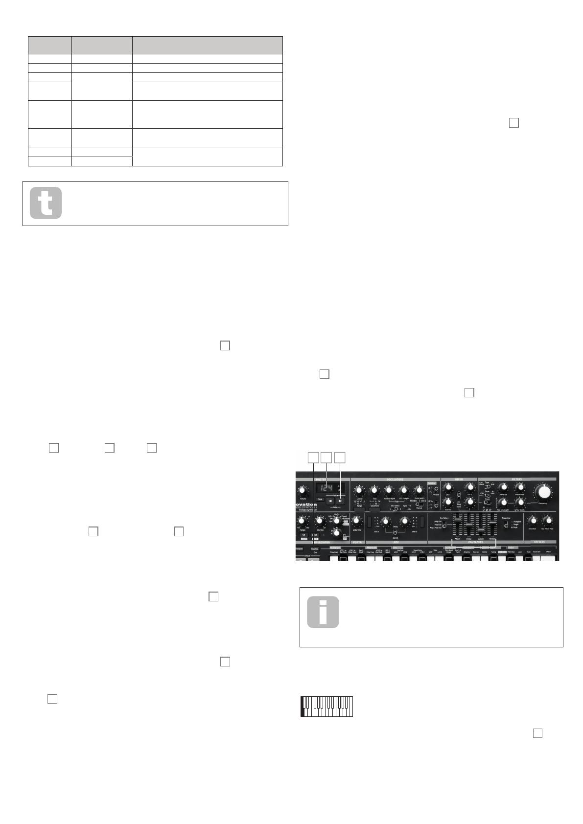
On-key Functions
To minimise the number of controls, Bass Station II uses On-key functions to adjust non-
performance sound parameters.
Each note on the keyboard has a specific On-key function, and these are marked on the
panel above each key. To use an On-key function press and hold the Function/Exit
button
51
and press the key corresponding to the desired function. The LED display will
flash, showing the current value or setting of the function. Release both the key and the
Function/Exit button, and use the Patch/Value buttons
8
to alter the value or state.
Note that some functions are “switch” type – i.e., On/Off, while others are “analogue” and
have a typical parameter value range from -63 to +63. When the desired value or state has
been set, press Function/Exit again to exit the On-key mode; if you don’t make any further
adjustments it will time-out after 10 seconds.
6
85
Once the On-key function has been selected (with the LED display
flashing), the keyboard resumes normal operation. This allows any changes
to the sound resulting from alteration of the On-key function to be
auditioned live if necessary. For example, changing the Arp Swing
parameter in a live performance.
Many of the On-key functions are described elsewhere in the manual; the list below
provides a full summary.
Mod Wh: Filter Freq (bottom C)
Range: -63 to +63
As well as varying the filter cut-off frequency manually (with the Frequency control
33
), with the Modulation Envelope, and with LFO 2, you can also use the Mod Wheel to vary
it. This is great feature in live performance. The parameter value effectively determines the
range of control available from the wheel. Positive values of the parameter increase the
filter cut-off frequency as the mod wheel is moved away from you; negative values have the
opposite effect.
18
Mod Wh: LFO 1 to OSC Pitch (lower C#)
Range: -63 to +63
The LFO 1 to OSC Pitch parameter controls the degree to which the oscillator pitch (both
Osc 1 and Osc 2) is modified by LFO 1 when using the Mod wheel
2
. This function is
summed with all other oscillator pitch controls, therefore its specific effect will also depend
on the other oscillator pitch control settings. Positive values increase the modulation,
resulting in a maximum pitch change of 96 semitones, or 8 octaves. Negative values
reduce the oscillator pitch modulation by a similar maximum amount.
Mod Wh: LFO 2 to Filter Freq (lower D)
Range: -63 to +63
The LFO 2 to Filter Freq parameter controls the degree to which the filter frequency
is modified by LFO 2 when using the Mod wheel
2
. This function is summed with all
other filter frequency controls, therefore its specific effect will also depend on the other
filter frequency control settings. Positive values increase the filter frequency modulation,
negative values decrease it.
Mod Wh: Osc 2 Pitch (lower D#)
Range: -63 to +63
The Osc 2 Pitch parameter controls the degree to which the pitch of Osc 2 is modified
when using the Mod wheel
2
. This is useful for sweeping Osc 2 by a greater amount than
is possible using the Pitch wheel. Positive values increase the modulation, resulting in a
maximum pitch change of 96 semitones, or 8 octaves. Negative values reduce the oscillator
pitch modulation by a similar maximum amount.
Aftertouch: Filter Freq (lower E)
Range: -63 to +63
The Filter Freq parameter controls the degree to which the filter frequency is modified
by aftertouch (i.e., the change in filter frequency is proportional to the amount of
pressure applied to the key once it is struck). Positive values increase the filter frequency
modulation, negative values decrease it.
Aftertouch: LFO 1 to OSC Pitch (lower F)
Range: -63 to +63
The LFO 1 to OSC Pitch parameter controls the degree to which the oscillator pitch
(for both Osc 1 and Osc 2) is modified by LFO 1 when using aftertouch. This function
is summed with the other oscillator pitch controls, therefore its specific effect will
also depend on the other oscillator pitch control settings. Positive values increase the
modulation, resulting in a maximum pitch change of 95 semitones, or 8 octaves. Negative
values reduce the oscillator pitch modulation by a similar maximum amount.
Aftertouch: LFO 2 Speed (lower F#)
Range: -63 to +63
The LFO 2 Speed parameter controls the degree to which aftertouch affects LFO 2
speed. Positive values increase the speed in proportion to the amount of pressure applied
to the key. Negative values decrease the speed of LFO 2.
LFO: Keysync LFO 1 (lower G)
Range: On or Off
Setting Keysync LFO 1 to On re-starts LFO 1 at the start of the waveform every time a key
is pressed. If set to Off it is not possible to predict where the waveform will be when a key
is pressed.
LFO: Keysync LFO 2 (lower G#)
Range: On or Off
Setting Keysync LFO 2 to On re-starts LFO 2 at the start of the waveform every time a key
is pressed. If set to Off it is not possible to predict where the waveform will be when a key
is pressed.
LFO: Speed/Sync LFO 1 (lower A)
Range: SPd or Snc
This On-key function relates to the Delay/Speed switch
23
in the LFO section. When
Delay/Speed is set to Speed, it is possible to extend its function by using the Speed/
Sync On-Key function. Setting Speed/Sync LFO 1 to Speed allows the speed of LFO 1
to be controlled by the rotary control
25
. Setting it to Sync reassigns the function of this
control, and allows the speed of LFO 1 to be synchronised to an internal or external MIDI
clock, based on a sync value selected by the control
25
. Sync values are shown on the
LED display. See Sync Values table on page 19.
LFO: Speed/Sync LFO 2 (lower A#)
Range: SPd or Snc
This On-key function operates in a similar manner to LFO: Speed/Sync LFO 1 above.
LFO: Slew LFO 1 (lower B)
Range: 0 to 127
Slew has the effect of modifying the shape of the LFO 1 waveform. Sharp edges become
less sharp as the value of Slew is increased.
LFO: Slew LFO 2 (middle C)
Range: 0 to 127
This On-key function operates in a similar manner to Slew LFO 1 above, but varies the
slew for LFO 2.
Oscillator: Pitch Bend Range (upper C#)
Range: -24 to +24
The Pitch Bend Range parameter determines the maximum range (in semitones) that a
note can be raised or lowered using the Pitch wheel
2
. A maximum of two octaves can
be selected. A positive value increases the pitch of a note when the Pitch wheel is rotated
forwards” and decrease its pitch when it is rotated “backwards”. A negative Pitch Bend
value reverses this relationship.
Oscillator: Osc 1-2 sync (upper D)
Range: Off or On
Osc 1-2 sync is a technique of using Osc 1 to add harmonics to Osc 2 by using oscillator
1’s waveform to re-trigger that of oscillator 2. When OSC 1-2 sync is On, the Sync 1-2 LED
[20] is illuminated. See page 9 for further details.
Velocity: Amp Env (upper D#)
Range: -63 to +63
This function adds touch sensitivity to overall volume, so that with positive parameter
values, the harder you play the keys, the louder will be the sound. With Amplitude
Velocity set to zero, the volume is the same regardless of how the keys are played. The
relationship between the velocity at which a note is played and volume is determined by the
value. Note that negative values have the inverse effect.
For the most “natural” playing style, try setting Amp Env to about +40.
Velocity: Mod Env (upper E)
Range: -63 to +63
As Amp Env adds touch sensitivity to volume, so Mod Env can be set to make the effect
of anything being controlled by the Modulation envelope become touch sensitive. With
positive parameter values, the harder you play the keys, the greater will be the effect of the
modulation. Note that negative values have the inverse effect.
VCA: Limiter (upper F)
Range: 0 to 127
Because Bass Station II can generate a very wide dynamic range – particularly if the filter
section is adjusted close to self-oscillation – it may be desirable to apply limiting to the
synth output to control the signal level. This On-key function applies a simple limiter (there
are no other controls) to the VCA stage. It is best adjusted after all other sound parameters
have been tweaked; if possible, set it while checking the output level on the meter of a
mixer or amplifier to ensure that no clipping occurs while any in-performance controls are
adjusted. As the parameter value is increased, the limiting becomes more severe, resulting
in a compressed sound at lower output level. You may have to turn the volume up externally
to compensate for limiting.
19
Arp: Swing (upper F#)
Range: 1% to 99%
This modies the rhythm of the current arp pattern. See page 17 for a full description.
Arp: Seq Retrig (upper G)
Range: Off or On
This forces a repeat of the current sequencer pattern regardless of the length of the arp
pattern. See page 17 for a full description.
Global: MIDI Channel (upper G#)
Range: 1 to 16
This On-key function lets you select the MIDI channel to be used for transmitting and
receiving MIDI data to/from other equipment (such as the MIDI sequencer within your
DAW). Hold the Function/Exit button
5
down and press the upper G note. The display
will flash, showing the current MIDI channel number (1 if it has not been changed from the
factory default). Release Function/Exit. You can now use the Patch/Value keys to alter
the channel number. The new channel number will be stored and reinstated after a power-
down.
Global: Local (upper A)
Range: On or Off
This control determines whether Bass Station II is to be played from its own keyboard, or
to respond to MIDI control from an external device, such as a MIDI sequencer or master
keyboard. Set Local to On to use the keyboard, and to Off if you are going to control the
synth externally via MIDI or use Bass Station II’s keyboard other external MIDI devices.
Global: Tune (upper A#)
Range: -50 cents to +50 cents
This parameter lets you make finer adjustments to the overall synth tuning. The increments
are cents (1/100 of a semitone), and thus setting the value to ±50 tunes the oscillator to a
quarter-tone midway between two semitones.
Global: Input Gain (upper B)
Range: -10 dB to +60 dB
This adjusts the gain of the external audio input applied at the rear panel EXT IN connector
{6}. The default value is zero (unity gain)
Global: Dump (upper C)
Range: n/a
Use this On-key function to transmit current synth parameters via MIDI as a SysEx
message. This allows you to store personal Patches on your computer for back-up
purposes. The data is transmitted from both the USB port and MIDI OUT sockets on the
rear panel. You can either transmit just the current Patch, or all 128. Hold the Function/
Exit button and hit the key. The display will show onE. Keeping the Function/Exit
button pressed, hit the key again, and all current synth parameters will be transmitted.
Alternatively, press the Patch/Value buttons, the display will show All. Keeping the
Function/Exit button pressed, hit the key again; Bass Station II will now transmit the
parameters of all 128 Patches in sequence, so that you will have a backup of your entire
synth.
APPENDIx
Importing Patches via SysEx
The On-Key Dump function lets you save any or all of your Bass Station II Patches to a
computer by transmitting the data in the form of MIDI SysEx messages. This would not be
very useful without a method of loading Patches into the synth from the computer!
In addition to loading Patches which you may have saved, you may also want to load new
Patches which you have downloaded from the Novation website. (Remember to check the
website from time to time, as our sound programming team is constantly coming up with
great new sounds for you to use.)
Use whatever MIDI software you have installed on your computer to upload Patches as
SysEx data. You will need to know where the Patch files are saved on your hard drive, of
course.
When you send a single Patch from your computer, Bass Station II loads it into a buffer
memory, but it becomes the currently active Patch – i.e., you can use it straightaway.
However, if you change to another Patch on the synth, the uploaded Patch will be lost. If
you want to upload a Patch into your synth and save it for future use, you must Save it in the
normal manner (see “Saving Patches” on page 7). As with saving any modified Patch,
if you just press Save, the Patch in the currently-selected location will be overwritten. If you
want to Save the uploaded Patch in a specic memory location (Patch number), you must
first scroll to that location before Saving.
If you send a complete patch library, you will automatically overwrite every Patch in the
synth. This is useful – as it allows you to restore the synth to its original factory Patch
settings – but note that it will overwrite all existing Patches, so if you have not backed them
up they will be lost. Use with caution!
Sync values table
This table explains what the display will show when altering the Speed/Sync setting for
either of the LFOs (by turning the LFO rotary controls [25] when On-Key function LFO:
Speed/Sync LFO 1 is set to Sync).
Display
Display
Meaning
Musical Description
MIDI
Ticks
1 64b 64 beats 1 cycle per 16 bars 1536
2 48b 48 beats 1 cycle per 12 bars 1152
3 42b 42 beats 2 cycles per 21 bars 1002
4 36b 36 beats 1 cycle per 9 bars 864
5 32b 32 beats 1 cycle per 8 bars 768
6 30b 30 beats 2 cycles per 15 bars 720
7 28b 28 beats 1 cycle per 7 bars 672
8 24b 24 beats 1 cycle per 6 bars 576
9 213 21 + 2/3 3 cycles per 16 bars 512
10 20b 20 beats 1 cycle per 5 bars 480
11 183 18+ 2/ 3 3 cycles per 14 bars 448
12 18b 18 beats 1 cycle per 18 beats (2 cycles per 9 bars) 432
13 16b 16 beats 1 cycle per 4 bars 384
14 133 13 + 1/3 3 cycles per 4 bars 320
15 12b 12 beats 1 cycle per 12 beats (1 cycle per 3 bars) 288
16 102 10 + 2/3 3 cycles per 8 bars 256
17 8b 8 beats 1 cycle per 2 bars 192
18 6b 6 beats 1 cycle per 6 beats (2 cycles per 3 bars) 144
19 5b3 5 + 1/3 3 cycles per 4 bars 128
20 4b 4 beats 1 cycle per 1 bar 96
21 3b 3 beats 1 cycle per 3 beats (4 cycles per 3 bars) 72
22 8x3 2 + 2/3 3 cycles per 2 bars 64
23 2n 2nd 2 cycles per 1 bar 48
24 4d 4th dotted 2 cycles per 3 beats (8 cycles per 3 bars) 36
25 4x3 1 + 1/3 3 cycles per 1 bar 32
26 4n 4th 4 cycles per 1 bar 24
27 8d 8th dotted 4 cycles per 3 beats (16 cycles per 3 bars) 18
28 4t 4th triplet 6 cycles per 1 bar 16
29 8n 8th 8 cycles per 1 bar 12
30 16d 16th dotted 8 cycles per 3 beats (32 cycles per 3 bars) 9
31 8t 8th triplet 12 cycles per 1 bar 8
32 16n 16th 16 cycles per 1 bar 6
33 16t 16th triplet 24 cycles per 1 bar 4
34 32n 32nd 32 cycles per 1 bar 3
35 32t 32nd triplet 48 cycles per 1 bar 2
20
Init Patch – parameter table
This list gives the values of all synth parameters in the Init Patch (the factory Patch initially
loaded into Patch memories 64 to 127):
Section Parameter Initial Value
Master patch volume 100
Oscillator Osc 1 fine 0 (centre)
Osc 1 range 8’ (A3=440Hz)
Osc 1 coarse 0 (centre)
Osc 1 waveform saw
Osc 1 Mod Env depth 0 (centre)
Osc 1 LFO 1 depth 0 (centre)
Osc 1 Mod Env PW mod amount 0 (centre)
Osc 1 LFO 2 PW mod amount 0 (centre)
Osc 1 manual PW amount 50. (centre)
Osc 2 fine 0 (centre)
Osc 2 range 8’ (A3=440Hz)
Osc 2 coarse 0 (centre)
Osc 2 waveform saw
Osc 2 Mod Env depth 0 (centre)
Osc 2 LFO 1 depth 0 (centre)
Osc 2 env 2 PW mod amount 0 (centre)
Osc 2 LFO 2 PW mod amount 0 (centre)
Osc 2 manual PW amount 50. (centre)
Sub Osc oct -1
Sub Osc wave sine
Mixer Osc 1 level 255 (right)
Osc 2 level 0 (left)
Sub Osc level 0 (left)
Select noise, ring, ext 0 (left)
Noise level 0 (left)
Ring mod level 0 (left)
External signal level 0 (left)
Filter Type Classic
Slope 24dB
Shape LP
Frequency 255 (right)
Resonance 0 (left)
Mod Env depth 0 (centre)
LFO 2 depth 0 (centre)
Overdrive 0 (centre)
Portamento Portamento time 0 (left)
LFOs LFO 1 speed 75 (7.9Hz)
LFO 1 delay 0 (left)
LFO 2 speed 52 (3Hz)
LFO 2 delay 0 (left)
LFO 1 wave tri
LFO 2 wave tri
LFO 1 Sync value off
LFO 2 Sync value on
Envelope Amp env attack 0 (bottom)
Amp env decay 0 (bottom)
Amp env sustain 127 (up)
Amp env release 0 (bottom)
Amp env triggering Multi
Mod Env attack 0 (bottom)
Mod Env decay 0 (bottom)
Mod Env sustain 127 (right)
Mod Env release 0 (bottom)
Mod Env triggering Multi
Amp and Mod Env triggering Multi
Effects Distortion 0 (left)
Osc Filter Mod 0 (left)
Arpeggiator On off
Latch off
Rhythm 32
Note mode up
Octaves 1
Octave Area Key transpose 0
Octave 0
Other Mod 0
On Key Functions
Mod Wh LFO 2 Filter Freq 0
LFO 1 Osc Pitch 10
Osc 2 Pitch 0
Aftertouch Filter Freq 10
LFO 1 to Osc Pitch 0
LFO 2 Speed 0
LFO Key Sync LFO 1 off
Key Sync LFO 2 on
Speed/Sync LFO 1 speed
Speed/Sync LFO 2 speed
Slew LFO 1 0
Slew LFO 2 0
Oscillator Bend Amount 12 (oct up and down)
Osc 1-2 Sync off
Velocity Amp Env 0
Mod Env 0
VCA Limit 0
Arp Arp Swing 50
Seq Retrig on
Global MIDI Chan 1
Local on
Tune 0
Input Gain 0
Synth settings saved on power-off
1 Input Gain
2 Master Tune
3 MIDI Channel
Synth settings not saved on power-off
1 Local setting is not retained. Default to ON
2 Editable patch memory (if not Saved to a preset location)
3 Current patch number. Defaults to patch zero
  • Page 1 1
  • Page 2 2
  • Page 3 3
  • Page 4 4
  • Page 5 5
  • Page 6 6
  • Page 7 7
  • Page 8 8
  • Page 9 9
  • Page 10 10
  • Page 11 11
  • Page 12 12
  • Page 13 13
  • Page 14 14
  • Page 15 15
  • Page 16 16
  • Page 17 17
  • Page 18 18
  • Page 19 19
  • Page 20 20
  • Page 21 21
  • Page 22 22

Vivanco UNIVERSAL SWITCHMODE AC TO DC MAINS ADAPTERS WITH USB CHARGING FUNCTION User guide

Category
Supplementary music equipment
Type
User guide
This manual is also suitable for

Ask a question and I''ll find the answer in the document

Finding information in a document is now easier with AI