Page is loading ...

11
11
1
P4i945GC
User Manual
Version 1.0
Published June 2009
Copyright©2009 ASRock INC. All rights reserved.

22
22
2
Copyright Notice:Copyright Notice:
Copyright Notice:Copyright Notice:
Copyright Notice:
No part of this manual may be reproduced, transcribed, transmitted, or translated in
any language, in any form or by any means, except duplication of documentation by
the purchaser for backup purpose, without written consent of ASRock Inc.
Products and corporate names appearing in this manual may or may not be regis-
tered trademarks or copyrights of their respective companies, and are used only for
identification or explanation and to the owners’ benefit, without intent to infringe.
Disclaimer:Disclaimer:
Disclaimer:Disclaimer:
Disclaimer:
Specifications and information contained in this manual are furnished for informa-
tional use only and subject to change without notice, and should not be constructed
as a commitment by ASRock. ASRock assumes no responsibility for any errors or
omissions that may appear in this manual.
With respect to the contents of this manual, ASRock does not provide warranty of
any kind, either expressed or implied, including but not limited to the implied warran-
ties or conditions of merchantability or fitness for a particular purpose.
In no event shall ASRock, its directors, officers, employees, or agents be liable for
any indirect, special, incidental, or consequential damages (including damages for
loss of profits, loss of business, loss of data, interruption of business and the like),
even if ASRock has been advised of the possibility of such damages arising from any
defect or error in the manual or product.
This device complies with Part 15 of the FCC Rules. Operation is subject to the
following two conditions:
(1) this device may not cause harmful interference, and
(2) this device must accept any interference received, including interference that
may cause undesired operation.
CALIFORNIA, USA ONLY
The Lithium battery adopted on this motherboard contains Perchlorate, a toxic
substance controlled in Perchlorate Best Management Practices (BMP) regulations
passed by the California Legislature. When you discard the Lithium battery in
California, USA, please follow the related regulations in advance.
“Perchlorate Material-special handling may apply, see
www.dtsc.ca.gov/hazardouswaste/perchlorate”
ASRock Website: http://www.asrock.com

33
33
3
ContentsContents
ContentsContents
Contents
1 Introduction1 Introduction
1 Introduction1 Introduction
1 Introduction
......................................................................................................
......................................................................................................
...................................................
5 5
5 5
5
1.1 Package Contents.......................................................... 5
1.2 Specifications ................................................................ 6
1.3 Motherboard Layout ...................................................... 9
1.4 ASRock 8CH I/O Plus ..................................................... 10
2 Installation2 Installation
2 Installation2 Installation
2 Installation
............................................................................................................
............................................................................................................
......................................................
11 11
11 11
11
Pre-installation Precautions ................................................... 11
2.1 CPU Installation .............................................................. 12
2.2 Installation of CPU Fan and Heatsink ............................ 12
2.3 Installation of Memory Modules (DIMM)......................... 13
2.4 Expansion Slots (PCI and PCI Express Slots) ..................... 14
2.5 Jumpers Setup .............................................................. 15
2.6 Onboard Headers and Connectors .............................. 16
2.7 SATAII Hard Disk Setup Guide ....................................... 20
2.8 Serial ATA (SATA) / Serial ATAII (SATAII) Hard Disks
Installation ...................................................................... 21
2.9 Driver Installation Guide ............................................... 21
2.10 Untied Overclocking Technology................................... 21
3 BIOS S3 BIOS S
3 BIOS S3 BIOS S
3 BIOS S
ETUP UTILITYETUP UTILITY
ETUP UTILITYETUP UTILITY
ETUP UTILITY
......................................................................................
......................................................................................
...........................................
22 22
22 22
22
3.1 Introduction .................................................................... 22
3.1.1 BIOS Menu Bar .................................................... 22
3.1.2 Navigation Keys ................................................... 23
3.2 Main Screen................................................................... 23
3.3 Smart Screen ................................................................ 24
3.4 Advanced Screen ......................................................... 25
3.4.1 CPU Configuration................................................ 25
3.4.2 Chipset Configuration .......................................... 27
3.4.3 ACPI Configuration ............................................... 30
3.4.4 IDE Configuration ................................................. 31
3.4.5 PCIPnP Configuration ........................................... 33
3.4.6 Floppy Configuration ........................................... 34
3.4.7 Super IO Configuration ........................................ 34
3.4.8 USB Configuration ............................................... 35
3.5 Hardware Health Event Monitoring Screen .................. 36
3.6 Boot Screen................................................................... 37
3.6.1 Boot Settings Configuration.................................. 37
3.7 Security Screen ............................................................ 38
3.8 Exit Screen .................................................................... 39

44
44
4
4 Software Support4 Software Support
4 Software Support4 Software Support
4 Software Support
......................................................................................
......................................................................................
...........................................
40 40
40 40
40
4.1 Install Operating System ............................................... 40
4.2 Support CD Information ................................................. 40
4.2.1 Running Support CD ............................................ 40
4.2.2 Drivers Menu........................................................ 40
4.2.3 Utilities Menu ........................................................ 40
4.2.4 Contact Information.............................................. 40

55
55
5
Chapter 1 IntroductionChapter 1 Introduction
Chapter 1 IntroductionChapter 1 Introduction
Chapter 1 Introduction
Thank you for purchasing ASRock P4i945GC motherboard, a reliable motherboard
produced under ASRock’s consistently stringent quality control. It delivers excellent
performance with robust design conforming to ASRock’s commitment to quality and
endurance.
In this manual, chapter 1 and 2 contain introduction of the motherboard and step-by-
step guide to the hardware installation. Chapter 3 and 4 contain the configuration
guide to BIOS setup and information of the Support CD.
Because the motherboard specifications and the BIOS software might be
updated, the content of this manual will be subject to change without
notice. In case any modifications of this manual occur, the updated
version will be available on ASRock website without further notice. You
may find the latest VGA cards and CPU support lists on ASRock website
as well. ASRock website
http://www.asrock.com
If you require technical support related to this motherboard, please visit
our website for specific information about the model you are using.
www.asrock.com/support/index.asp
1.1 P1.1 P
1.1 P1.1 P
1.1 P
ackack
ackack
ack
age Contentsage Contents
age Contentsage Contents
age Contents
ASRock P4i945GC Motherboard
(Micro ATX Form Factor: 9.6-in x 7.7-in, 24.4 cm x 19.6 cm)
ASRock P4i945GC Quick Installation Guide
ASRock P4i945GC Support CD
One 80-conductor Ultra ATA IDE Ribbon Cable (Optional)
One Serial ATA (SATA) Data Cable (Optional)
One I/O Panel Shield

66
66
6
1.21.2
1.21.2
1.2
SpecificationsSpecifications
SpecificationsSpecifications
Specifications
Platform - Micro ATX Form Factor: 9.6-in x 7.7-in, 24.4 cm x 19.6 cm
CPU - Socket 478 for Intel
®
Pentium
®
4 / Celeron
®
D (Prescott,
Northwood) processors
- FSB 800/533/400 MHz (see CAUTION 1)
- Supports Hyper-Threading Technology (see CAUTION 2)
- Supports Untied Overclocking Technology (see CAUTION 3)
Chipset - Northbridge: Intel
®
945GC
- Southbridge: Intel
®
ICH7
Memory - 2 x DDR2 DIMM slots
- Supports DDR2 667/533/400 non-ECC, un-buffered memory
(see CAUTION 4)
- Max. capacity of system memory: 4GB (see CAUTION 5)
Expansion Slot - 1 x PCI Express x16 slot
- 1 x PCI Express x1 slot
- 2 x PCI slots
Graphics - Intel
®
Graphics Media Accelerator 950
- Pixel Shader 2.0, DirectX 9.0
- Max. shared memory 224MB (see CAUTION 6)
Audio - 7.1 CH Windows
®
Vista
TM
Premium Level HD Audio
(Realtek ALC888 Audio Codec)
LAN - PCIE x1 Gigabit LAN 10/100/1000 Mb/s
- Realtek RTL8111DL
- Supports Wake-On-LAN
Rear Panel I/O ASRock 8CH I/O Plus
- 1 x PS/2 Mouse Port
- 1 x PS/2 Keyboard Port
- 1 x Serial Port: COM1
- 1 x VGA Port
- 1 x Parallel Port (ECP/EPP Support)
- 4 x Ready-to-Use USB 2.0 Ports
- 1 x RJ-45 LAN Port
- HD Audio Jack: Side Speaker / Rear Speaker / Central / Bass
/ Line in / Front Speaker / Microphone (see CAUTION 7)
Connector - 4 x SATAII 3.0 Gb/s connectors (No Support for RAID and
“Hot Plug” functions) (see CAUTION 8)
- 1 x ATA100 IDE connector by Intel
®
ICH7 (supports 2 x IDE
devices)
- 1 x ATA133 IDE connector by VIA
®
VT6415 (supports 2 x IDE
devices)

77
77
7
- 1 x Floppy connector
- CPU/Chassis FAN connector
- 24 pin ATX power connector
- 4 pin 12V power connector
- CD in header
- Front panel audio connector
- 2 x USB 2.0 headers (support 4 USB 2.0 ports)
(see CAUTION 9)
BIOS Feature - 4Mb AMI BIOS
- AMI Legal BIOS
- Supports “Plug and Play”
- ACPI 1.1 Compliance Wake Up Events
- Supports jumperfree
- AMBIOS 2.3.1 Support
- Supports Smart BIOS
Support CD - Drivers, Utilities, AntiVirus Software (Trial Version)
Unique Feature - Instant Boot
- ASRock Instant Flash (see CAUTION 10)
- Hybrid Booster:
- CPU Frequency Stepless Control (see CAUTION 11)
- ASRock U-COP (see CAUTION 12)
- Boot Failure Guard (B.F.G.)
Hardware - CPU Temperature Sensing
Monitor - Chassis Temperature Sensing
- CPU Fan Tachometer
- Chassis Fan Tachometer
- Voltage Monitoring: +12V, +5V, +3.3V, Vcore
OS - Microsoft
®
Windows
®
2000 / XP / Vista
TM
compliant
Certifications - FCC, CE, WHQL
* For detailed product information, please visit our website: http://www.asrock.com
WARNING
Please realize that there is a certain risk involved with overclocking, including adjusting
the setting in the BIOS, applying Untied Overclocking Technology, or using the third-
party overclocking tools. Overclocking may affect your system stability, or even
cause damage to the components and devices of your system. It should be done at
your own risk and expense. We are not responsible for possible damage caused by
overclocking.

88
88
8
CAUTION!
1. If you adopt FSB400-CPU on this motherboard, you need to adjust the
jumpers. Please refer to page 15 for proper jumper settings.
2. About the setting of “Hyper Threading Technology”, please check page 26.
3. This motherboard supports Untied Overclocking Technology. Please read
“Untied Overclocking Technology” on page 21 for details.
4. Please check the table below for the CPU FSB frequency and its corre-
sponding memory support frequency.
CPU FSB Frequency Memory Support Frequency
800 DDR2 400, DDR2 533, DDR2 667
533 DDR2 400, DDR2 533
400 DDR2 400
5. Due to the chipset limitation, the actual memory size may be less than
4GB for the reservation for system usage under Windows
®
XP and
Windows
®
Vista
TM
.
6. The maximum shared memory size is defined by the chipset vendor and
is subject to change. Please check Intel
®
website for the latest information.
7. For microphone input, this motherboard supports both stereo and mono
modes. For audio output, this motherboard supports 2-channel, 4-channel,
6-channel, and 8-channel modes. Please check the table on page 10 for
proper connection.
8. Before installing SATAII hard disk to SATAII connector, please read the “SATAII
Hard Disk Setup Guide” on page 20 to adjust your SATAII hard disk drive to
SATAII mode. You can also connect SATA hard disk to SATAII connector
directly.
9. Power Management for USB 2.0 works fine under Microsoft
®
Windows
®
Vista
TM
/ XP SP1 or SP2 / 2000 SP4.
10. ASRock Instant Flash is a BIOS flash utility embedded in Flash ROM.
This convenient BIOS update tool allows you to update system BIOS
without entering operating systems first like MS-DOS or Windows
®
. With
this utility, you can press <F6> key during the POST or press <F2> key to
BIOS setup menu to access ASRock Instant Flash. Just launch this tool
and save the new BIOS file to your USB flash drive, floppy disk or hard
drive, then you can update your BIOS only in a few clicks without prepar-
ing an additional floppy diskette or other complicated flash utility. Please
be noted that the USB flash drive or hard drive must use FAT32/16/12 file
system.
11. Although this motherboard offers stepless control, it is not recommended
to perform over-clocking. Frequencies other than the recommended CPU
bus frequencies may cause the instability of the system or damage the
CPU.
12. While CPU overheat is detected, the system will automatically shutdown.
Before you resume the system, please check if the CPU fan on the
motherboard functions properly and unplug the power cord, then plug it
back again. To improve heat dissipation, remember to spray thermal
grease between the CPU and the heatsink when you install the PC system.

99
99
9
1.3 Motherboard Layout1.3 Motherboard Layout
1.3 Motherboard Layout1.3 Motherboard Layout
1.3 Motherboard Layout
1 PS2_USB_PWR1 Jumper 16 Chassis Speaker Header (SPEAKER 1, Purple)
2 CPU Fan Connector (CPU_FAN1) 17 USB 2.0 Header (USB6_7, Blue)
3 478-Pin CPU Socket 18 USB 2.0 Header (USB4_5, Blue)
4 CPU Heatsink Retention Module 19 System Panel Header (PANEL1, Orange)
5 2 x 240-pin DDR2 DIMM Slots 20 BIOS SPI Chip
(Dual Channel: DDRII_1, DDRII_2; Yellow) 21 Floppy Connector (FLOPPY1)
6 ATX Power Connector (ATXPWR1) 22 Front Panel Audio Header
7 Secondary IDE Connector (IDE2, Black) (HD_AUDIO1, Lime)
8 Primary IDE Connector (IDE1, Blue) 23 PCI Slots (PCI1- 2)
9 Clear CMOS Jumper (CLRCMOS1) 24 Internal Audio Connector: CD1 (Black)
10 South Bridge Controller 25 PCI Express x16 Slot (PCIE2)
11 Third SATAII Connector (SATAII_3; Orange) 26 PCI Express x1 Slot (PCIE1)
12 Fourth SATAII Connector (SATAII_4; Orange) 27 North Bridge Controller
13 Secondary SATAII Connector (SATAII_2; Red) 28 FD2 Jumper
14 Primary SATAII Connector (SATAII_1; Red) 29 FD0 Jumper
15 Chassis Fan Connector (CHA_FAN1) 30 ATX 12V Connector (ATX12V1)
19.6cm (7.7 in)
24.4cm (9.6 in)
Intel
945GC
Chipset
Intel
ICH7
PGA478
Top:
RJ-45
USB 2.0
T: USB2
B: USB3
USB 2.0
T: USB0
B: USB1
PARALLEL PORT
COM1
PS2
Mouse
PS2
Keyboard
VGA1
Top:
SIDE SPK
Center:
REAR SPK
Bottom:
CTR BASS
Top:
LINE IN
Center:
FRONT
Bottom:
MIC IN
ATX12V1
1
PS2_USB_PWR1
FSB800
DDRII_1 (64 bit, 240-pin module)
FSB800
DDRII_2 (64 bit, 240-pin module)
IDE1
IDE2
SATAII_3
SATAII_1
SATAII_4
SATAII_2
FD2
1
1
FD0
CLRCMOS1
CMOS
Battery
LAN
PHY
Super
IO
AUDIO
CODEC
CD1
PCIE1
PCIE2
PCI1
PCI2
SPEAKER1
1
1
USB6_7
1
USB4_5
CHA_FAN1
HD_AUDIO1
PANEL1
HDLED RESET
PLED PWRBTN
1
4Mb
BIOS
1
FLOPPY1
CPU_FAN1
P4i945GC
Dual Channel
DDR2 667
RoHS
Gigabit LAN
1
24
5
3
7
6
8
9
10
11
12
13
14
15
16
17
18
19
20
21
22
23
24
25
26
27
28
29
30

1010
1010
10
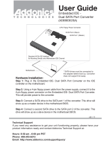
1.4 I/O Panel1.4 I/O Panel
1.4 I/O Panel1.4 I/O Panel
1.4 I/O Panel
1 PS/2 Mouse Port (Green) * 8 Front Speaker (Lime)
2 Parallel Port 9 Microphone (Pink)
3 RJ-45 Port 10 USB 2.0 Ports (USB01)
4 Side Speaker (Gray) 11 USB 2.0 Ports (USB23)
5 Rear Speaker (Black) 12 Serial Port: COM1
6 Central / Bass (Orange) 13 VGA Port
7 Line In (Light Blue) 14 PS/2 Keyboard Port (Purple)
1
2
4
3
5
6
7
8
9
10
11
12
13
14
* To enable Multi-Streaming function, you need to connect a front panel audio cable to the front
panel audio header. After restarting your computer, you will find “Mixer” tool on your system.
Please select “Mixer ToolBox” , click “Enable playback multi-streaming”, and click
“ok”. Choose “2CH”, “4CH”, “6CH”, or “8CH” and then you are allowed to select “Realtek HDA
Primary output” to use Rear Speaker, Central/Bass, and Front Speaker, or select “Realtek
HDA Audio 2nd output” to use front panel audio.

1111
1111
11
Chapter 2 InstallationChapter 2 Installation
Chapter 2 InstallationChapter 2 Installation
Chapter 2 Installation
P4i945GC is a Micro ATX form factor (9.6-in x 7.7-in, 24.4 cm x 19.6 cm) motherboard.
Before you install the motherboard, study the configuration of your chassis to en-
sure that the motherboard fits into it.
Pre-installation PrecautionsPre-installation Precautions
Pre-installation PrecautionsPre-installation Precautions
Pre-installation Precautions
Take note of the following precautions before you install motherboard com-
ponents or change any motherboard settings.
1. Unplug the power cord from the wall socket before touching any
component.
2. To avoid damaging the motherboard components due to static electricity,
NEVER place your motherboard directly on the carpet or the like. Also
remember to use a grounded wrist strap or touch a safety grounded
object before you handle components.
3. Hold components by the edges and do not touch the ICs.
4. Whenever you uninstall any component, place it on a grounded anti-
static pad or in the bag that comes with the component.
Before you install or remove any component, ensure that the power is
switched off or the power cord is detached from the power supply.
Failure to do so may cause severe damage to the motherboard,
peripherals, and/or components.

1212
1212
12
2.1 CPU Installation2.1 CPU Installation
2.1 CPU Installation2.1 CPU Installation
2.1 CPU Installation
Step 1. Unlock the socket by lifting the lever up to a 90° angle.
Step 2. Position the CPU directly above the socket such that its marked corner
matches the base of the socket lever.
Step 3. Carefully insert the CPU into the socket until it fits in place.
The CPU fits only in one correct orientation. DO NOT force the
CPU into the socket to avoid bending of the pins.
Step 4. When the CPU is in place, press it firmly on the socket while you push down
the socket lever to secure the CPU. The lever clicks on the side tab to
indicate that it is locked.
2.22.2
2.22.2
2.2
Installation of CPU Fan and HeatsinkInstallation of CPU Fan and Heatsink
Installation of CPU Fan and HeatsinkInstallation of CPU Fan and Heatsink
Installation of CPU Fan and Heatsink
This motherboard adopts 478-pin CPU socket to support Intel
®
Pentium
®
4
CPU. It requires larger heatsink and cooling fan to dissipate heat. You also
need to spray thermal grease between the CPU and the heatsink to
improve heat dissipation. Make sure that the CPU and the heatsink are
securely fastened and in good contact with each other. Then connect the
CPU fan to the CPU_FAN connector (CPU_FAN1, see page 9, No. 2). For
proper installation, please kindly refer to the instruction manuals of the
CPU fan and the heatsink.
STEP 1:
Lift The Socket Lever Up to 90°
STEP 2/STEP 3:
Match The CPU Marked Corner
to The Socket Marked Corner
STEP 4:
Push Down And Lock
The Socket Lever
Lift Lever Up to 90°
CPU Marked Corner
Socket Marked Corner

1313
1313
13
notch
break
notch
break
2.3 Installation of Memory Modules (DIMM)2.3 Installation of Memory Modules (DIMM)
2.3 Installation of Memory Modules (DIMM)2.3 Installation of Memory Modules (DIMM)
2.3 Installation of Memory Modules (DIMM)
P4i945GC motherboard provides two 240-pin DDR2 (Double Data Rate 2) DIMM
slots.
1. It is not allowed to install a DDR memory module into DDR2 slot;
otherwise, this motherboard and DIMM may be damaged.
2. Please make sure to disconnect power supply before adding or
removing DIMMs or the system components.
•
Step 1. Unlock a DIMM slot by pressing the retaining clips outward.
Step 2. Align a DIMM on the slot such that the notch on the DIMM matches the break
on the slot.
The DIMM only fits in one correct orientation. It will cause
permanent damage to the motherboard and the DIMM if you
force the DIMM into the slot at incorrect orientation.
Step 3. Firmly insert the DIMM into the slot until the retaining clips at both ends fully
snap back in place and the DIMM is properly seated.

1414
1414
14
2.4 Expansion Slots (PCI and PCI Express Slots)2.4 Expansion Slots (PCI and PCI Express Slots)
2.4 Expansion Slots (PCI and PCI Express Slots)2.4 Expansion Slots (PCI and PCI Express Slots)
2.4 Expansion Slots (PCI and PCI Express Slots)
There are 2 PCI slots and 2 PCI Express slots on this motherboard.
PCI slots: PCI slots are used to install expansion cards that have the 32-bit PCI
interface.
PCIE slots:
PCIE1 (PCIE x1 slot) is used for PCI Express cards with x1 lane width
cards, such as Gigabit LAN card, SATA2 card, etc.
PCIE2 (PCIE x16 slot) is used for PCI Express cards with x16 lane
width graphics cards.
If you install the add-on PCI Express VGA card to PCIE2 (PCIE x16 slot),
the onboard VGA will be disabled. If you install the add-on PCI Express
VGA card to PCIE2 (PCIE x16 slot) and adjust the “Internal Graphics
Mode Select” BIOS option to [Enabled, 1MB] or [Enabled, 8MB], the onboard
VGA will be enabled, and the primary screen will be onboard VGA.
Installing an expansion cardInstalling an expansion card
Installing an expansion cardInstalling an expansion card
Installing an expansion card
Step 1. Before installing the expansion card, please make sure that the power
supply is switched off or the power cord is unplugged. Please read the
documentation of the expansion card and make necessary hardware
settings for the card before you start the installation.
Step 2. Remove the bracket facing the slot that you intend to use. Keep the screws
for later use.
Step 3. Align the card connector with the slot and press firmly until the card is
completely seated on the slot.
Step 4. Fasten the card to the chassis with screws.

1515
1515
15
2.5 Jumpers Setup2.5 Jumpers Setup
2.5 Jumpers Setup2.5 Jumpers Setup
2.5 Jumpers Setup
The illustration shows how jumpers are
setup. When the jumper cap is placed on
pins, the jumper is “Short”. If no jumper cap
is placed on pins, the jumper is “Open”. The
illustration shows a 3-pin jumper whose pin1
and pin2 are “Short” when jumper cap is
placed on these 2 pins.
Jumper Setting Description
PS2_USB_PWR1 Short pin2, pin3 to enable
(see p.9 No. 1) +5VSB (standby) for PS/2
or USB wake up events.
Note: To select +5VSB, it requires 2 Amp and higher standby current provided by
power supply.
Clear CMOS
(CLRCMOS1, 2-pin jumper)
(see p.9 No. 9)
Note: CLRCMOS1 allows you to clear the data in CMOS. The data in CMOS includes
system setup information such as system password, date, time, and system
setup parameters. To clear and reset the system parameters to default setup,
please turn off the computer and unplug the power cord from the power
supply. After waiting for 15 seconds, use a jumper cap to short 2 pins on
CLRCMOS1 for 5 seconds.
FD Jumpers
(FD0 3-pin jumper, see p.9 No. 29)
(FD2 3-pin jumper, see p.9 No. 28)
Note: If you want to adopt FSB400-CPU on this motherboard, you need to adjust the
jumpers. Please short pin2, pin3 for FD0 jumper and pin2, pin3 for FD2 jumper.
Otherwise, the CPU may not work properly on this motherboard. Please refer
to below jumper settings.
+5V
1_2
+5VSB
2_3
2-pin jumper
1_2
Default
2_3
1_2
2_3

1616
1616
16
2.6 Onboard Headers and Connectors2.6 Onboard Headers and Connectors
2.6 Onboard Headers and Connectors2.6 Onboard Headers and Connectors
2.6 Onboard Headers and Connectors
Onboard headers and connectors are NOT jumpers. Do NOT place
jumper caps over these headers and connectors. Placing jumper caps
over the headers and connectors will cause permanent damage of the
motherboard!
FDD connector
(33-pin FLOPPY1)
(see p.9 No. 21)
Note: Make sure the red-striped side of the cable is plugged into Pin1 side of the
connector.
Primary IDE connector (Blue) Secondary IDE connector (Black)
(39-pin IDE1, see p.9 No. 8) (39-pin IDE2, see p.9 No. 7)
Note: If you use only one IDE device on this motherboard, please set the IDE
device as “Master”. Please refer to the instruction of your IDE device vendor
for the details. Besides, to optimize compatibility and performance, please
connect your hard disk drive to the primary IDE connector (IDE1, blue) and
CD-ROM to the secondary IDE connector (IDE2, black).
Serial ATAII Connectors These Serial ATAII (SATAII)
(SATAII_1: see p.9, No. 14) connectors support SATAII
(SATAII_2: see p.9, No. 13) or SATA hard disk for internal
(SATAII_3: see p.9, No. 11) storage devices. The current
(SATAII_4: see p.9, No. 12) SATAII interface allows up to
3.0 Gb/s data transfer rate.
Serial ATA (SATA) Either end of the SATA data cable
Data Cable can be connected to the SATA /
(Optional) SATAII hard disk or the SATAII
connector on the motherboard.
FLOPPY1
Pin1
the red-striped side to Pin1
SATAII_4
SATAII_3
SATAII_2
SATAII_1
IDE1
PIN1
IDE2
PIN1
connect the black end
to the IDE devices
connect the blue end
to the motherboard
80-conductor ATA cable

1717
1717
17
1. High Definition Audio supports Jack Sensing, but the panel wire on
the chassis must support HDA to function correctly. Please follow the
instruction in our manual and chassis manual to install your system.
2. If you use AC’97 audio panel, please install it to the front panel audio
header as below:
A. Connect Mic_IN (MIC) to MIC2_L.
B. Connect Audio_R (RIN) to OUT2_R and Audio_L (LIN) to OUT2_L.
C. Connect Ground (GND) to Ground (GND).
D. MIC_RET and OUT_RET are for HD audio panel only. You don’t
need to connect them for AC’97 audio panel.
E. Enter BIOS Setup Utility. Enter Advanced Settings, and then select
Chipset Configuration. Set the Front Panel Control option from
[Auto] to [Enabled].
CD-L
GND
GND
CD-R
CD1
J_SENSE
OUT2_L
1
MIC _RET
P R ESENCE#
GND
OUT2_R
MIC 2_R
MIC 2_L
OUT_R ET
USB 2.0 Headers Besides four default USB 2.0
(9-pin USB6_7) ports on the I/O panel, there are
(see p.9 No. 17) two USB 2.0 headers on this
motherboard. Each USB 2.0
header cansupport two USB
2.0 ports.
(9-pin USB4_5)
(see p.9 No. 18)
USB_P WR
USB_P WR
P +7
P-7
P +6
P-6
GND
GND
D U MMY
1
USB _PWR
USB _PWR
P+5
P-5
P+4
P-4
GND
GND
D UMMY
1
Internal Audio Connector This connector allows you
(4-pin CD1) to receive stereo audio input
(CD1: see p.9 No. 24) from sound sources such as
a CD-ROM, DVD-ROM, TV
tuner card, or MPEG card.
Front Panel Audio Header This is an interface for front
(9-pin HD_AUDIO1) panel audio cable that allows
(see p.9 No. 22) convenient connection and
control of audio devices.
connect to the SATA HDD
power connector
connect to the
power supply
Serial ATA (SATA) Please connect the black end of
Power Cable SATA power cable to the power
(Optional) connector on each drive. Then
connect the white end of SATA
power cable to the power
connector of the power supply.

1818
1818
18
+5V
D UMMY
D UMMY
SPEAKER
1
GND
PWRBTN#
PLED-
PLED +
D UMMY
RESET#
GND
H D LED+
H D LED-
1
System Panel Header This header accommodates
(9-pin PANEL1) several system front panel
(see p.9 No. 19) functions.
Chassis Speaker Header Please connect the chassis
(4-pin SPEAKER 1) speaker to this header.
(see p.9 No. 16)
Chassis Fan Connector Please connect a chassis fan
(3-pin CHA_FAN1) cable to this connector and
(see p.9 No. 15) match the black wire to the
ground pin.
CPU Fan Connector Please connect a CPU fan cable
(3-pin CPU_FAN1) to this connector and match
(see p.9 No. 2) the black wire to the ground pin.
F. Enter Windows system. Click the icon on the lower right hand
taskbar to enter Realtek HD Audio Manager.
For Windows
®
2000 / XP OS:
Click “Audio I/O”, select “Connector Settings” , choose
“Disable front panel jack detection”, and save the change by
clicking “OK”.
For Windows
®
Vista
TM
OS:
Click the right-top “Folder” icon , choose “Disable front
panel jack detection”, and save the change by clicking “OK”.
G. To activate the front mic.
For Windows
®
2000 / XP OS:
Please select “Front Mic” as default record device.
If you want to hear your voice through front mic, please deselect "Mute"
icon in “Front Mic” of “Playback” portion.
For Windows
®
Vista
TM
OS:
Go to the "Front Mic" Tab in the Realtek Control panel.
Click "Set Default Device" to make the Front Mic as the default record
device.
G ND
+12V
C HA_FAN_SPEED
CPU_FAN_SPEED
GND
+12V

1919
1919
19
20-Pin ATX Power Supply Installation
ATX 12V Connector Please note that it is necessary
(4-pin ATX12V1) to connect a power supply with
(see p.9 No. 30) ATX 12V plug to this connector
so that it can provides sufficient
power. Failing to do so will cause
the failure to power up.
ATX Power Connector Please connect an ATX power
(24-pin ATXPWR1) supply to this connector.
(see p.9, No. 6)
Though this motherboard provides 24-pin ATX power connector,
it can still work if you adopt a traditional 20-pin ATX power supply.
To use the 20-pin ATX power supply, please plug your power
supply along with Pin 1 and Pin 13.
12
1
24
13
12
1
24
13

2020
2020
20
2.72.7
2.72.7
2.7
SASA
SASA
SA
TT
TT
T
AII Hard Disk Setup GuideAII Hard Disk Setup Guide
AII Hard Disk Setup GuideAII Hard Disk Setup Guide
AII Hard Disk Setup Guide
Before installing SATAII hard disk to your computer, please carefully read below
SATAII hard disk setup guide. Some default setting of SATAII hard disks may not
be at SATAII mode, which operate with the best performance. In order to enable
SATAII function, please follow the below instruction with different vendors to
correctly adjust your SATAII hard disk to SATAII mode in advance; otherwise, your
SATAII hard disk may fail to run at SATAII mode.
Western Digital
If pin 5 and pin 6 are shorted, SATA 1.5Gb/s will be enabled.
On the other hand, if you want to enable SATAII 3.0Gb/s, please remove the
jumpers from pin 5 and pin 6.
SAMSUNG
If pin 3 and pin 4 are shorted, SATA 1.5Gb/s will be enabled.
On the other hand, if you want to enable SATAII 3.0Gb/s, please remove the
jumpers from pin 3 and pin 4.
HITACHI
Please use the Feature Tool, a DOS-bootable tool, for changing various ATA
features. Please visit HITACHI’s website for details:
http://www.hitachigst.com/hdd/support/download.htm
1357
2468
1357
2468
The above examples are just for your reference. For different SATAII hard
disk products of different vendors, the jumper pin setting methods may not
be the same. Please visit the vendors’ website for the updates.
/