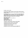
Craftsman 161.210400 Owner's manual
- Category
- Multimeters
- Type
- Owner's manual
This manual is also suitable for

IIIIIIIII I
2-170701
I [11 II ........
I II II - --_
l
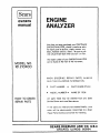
Sears
k ............. . ......
owners
manual
MODEL NO.
161.210400
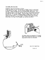
Caution:
Read Rules For
Safe Operation
and Complete
Operating Test
Procedures
Carefully
............ •........ . .....
PRINTED iN U.S.A.
.;_(/ )-
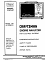
CRRFTSHRN
ENGINE ANALYZER
FOR 12& 24 VOLT SYSTEMS
. OPERATING INSTRUCTIONS
• SAFETY RULES
•TUNE- UP PROCEDURES
• REPAIR PARTS
,, ,,,, , ,, ,,,,,, , ,I .......... ' I I II Illl 11 IIIIIII IIII 11
SEARS, ROEBUCK AND CO. U.S.A.
CHICAGO, ILLINOIS 6068.4 ......
2-17070_

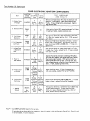
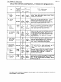
TOT Numld
TEST lll!lii(l
T[S? _UHO_X
!£ST llli_l
?_ST liilli_l
TEst m, ilIl
TEST _U_ER
tEPt.ACfi,I_
R(ILAc[,MENI
34€-*Lo_ v_XAG[ OnOPT(STS ................................ST
_I_--E|SStOII COtI_O. $#;1_ TIE.los ..................... S2
HF-_ illIIlllNGS ........................................ t8
lii--l[Ai Wlli!lOi lffN'OtTil IIlD ............................!!
_4B--ELEC?NICALiIRIN_ltARNE$S ............................. _9
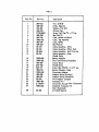
e,',_T_LIST .................................................$t

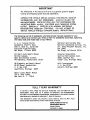
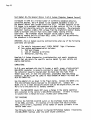
IMPORTANT
The information in thls manual will serve as a generaJ gulde for engine
tune-up and charging systemtests and adlustments.
CONSULT THE VEHICLE SERVICE MANUAL FOR SPECIFIC TUNE..UP
INFORMATION AND TEST PROCEDURES. ALWAYS FOLLOW THE
MANUFACTURER°S SPECIFICATIONS AND TEST PROCEDURES FOR
ADJUSTING DWELL ANGLEe IDLE SPEED AND CHARGING SYSTEM
OUTPUT, ESPECIALLY VEHICLES WITH MODERN ELECTRONIC
IGNITION AND EMISSION CONTROLS. DO NOT ATTEMPT TO
SERVICE VEHICLE WITHOUT MANUFACTURER'S INSTRUCTIONS.
The following Is a list of publishers who have service manuals available for your
specific vehicle at a nominal cost. Write to them for availability and prices, specifying
the make, style, and model year of your vehicle.
A. E. A. Tune-Up Charts
Automotive Electric Assn.
130i W. 22nd St., Suite 202
Executive Plaza Building
Oak Brook, Illinois 6052%
National Service Data Book
National Automotive Service, Inc.
Div. Glenn Mitchell Manuals, Inc.
Box 10465
San Diego, Ca]ifornia 92110
Chilton_s Auto Repair Manual
Chllton Company
56th and Chestnut Streets
Philadelphia, Pennsylvania 19139
GM Diagnosis and Repair Manual
GM DR Manual Headquarters
P. O. Box 1185
Southfield, Michigan 48075
Chrysler Corporation
Service Publications Dept.
26001 Lawrence Ave.
Center Line, Michigan 48015
Helm Incorporated
P. O. Box 07150
Detroit, Michigan 48207
Motor's Auto Repair Manual
250 W. 55th Street
New York, N. Y. 10019
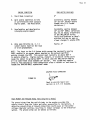
FULL 1 YEAR WARRANTY
IF, WITHIN 1 YEAR FROM THE DATE OF PURCHASE, THIS AUTOMOTIVE TEST
INSTRUMENT FALLS DUE TO A DEFECT iN MATERIAL OR WORKMANSHIP,
RETURN tT TO THE NEAREST SEARS STORE THROUGHOUT THE UNITED STATES÷
AND SEARS WILL REPAIR OR REPLACE iT, FREE OF CHARGE.
THIS WARRANTY GIVES YOU SPECIFIC LEGAL RIGHTS, AND YOU MAY ALSO
HAVE OTHER RIGHTS WHICH VARY FROM STATE TO STATE.
SEARS, ROEBUCK AND CO,
DEPARTMENT 898/731A
SEARS TOWER
CHICAGO, IL 60684

Wage
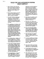
RULESFOR SAFE AUTOMOTIVE TESTING
READ CAREFULLY
2_
3_
e
,
B
e
Read this Owner's Manual and these
Rules for Safe Automotive Testing core-
fully. Fa_iure to Follow instructions
and safety _ies could result tn serious
bodily _nlury and/or damage to the
Instrument.
Beforestarting the englne_ set the park.,
Ing brake and place gear selector In
NEUTRAL an standard transmissionsor
PARKon automatic transmission.
The carbon monoxide in exhaust gas is
highly toxic. To avoid asphyxiation,
alway_ operate vehlcle In a well..
ventilated area. if vehicle Is In an en-
closed arean exhaust should be routed
dtrectly to the outside via leakproof ex-
haust hose.
Whenoperating any test instrument from
on auxiliary battery+ connect a jumper
wlre between the negative terminal of
the aux_llary battery and chards ground
on the vehicle under test for negative
groundsysten_h Forpositive ground
systems+connect the jumperwire to the
positive terminal of the auxll _ary battery
and chosdsground an the vehicle.
Whenworking in a garage or other en-
closedarea, auxii la_ battery should be
located at least 18 Inches above the floor
to minimize the potsibllity of spork_
;gniHng gasolinevaporsand causlng an
explosion.
An automobile battery Is €apable or pm-
duc|ng very hlgh currents. Therefore,
exercise reasonable care when working
near the battery to avoid electrical con-
nectionsthroughtools, wristwatch, etc.
Avoid contact with battery electrolyte.
It can eat holes In clathlng, burn skin
and cause permanent damage to eyes.
Always wear q_iash proof safety goggles
when working around the battery, if
battery electrolyte is splashed in the
eyes or on skln, immediately flush the
affected area for 15 minutes with large
quantities of clean water. In case of
eye €ontact0 seek medical a_d,
The gasesgenerated by a chargtng bat-.
tory are highly explosive. Do not
smokeor permit flame or spark to occur
near o battery at any tlme+ particular-
ly when it Is charglng. Any roomor
v
9_
10.
II.
i2.
13.
14.
15.
comportment€ontaining charging bat..
terles shouldbe well ventilated to
prevent accumulaHon of explosive
gases. To avoid spark_, do ru_tdisturb
the battery charger connectlonswhile
battery is charglngs and always turn
charger off before dlsconnecti_'gthe
battery clips. When removing or re-
connecting battery cables, make sure
Ignition switch and all acce.orles are
turned off.
Never add acid to a battery once the
battery has been placed In service.
Doing so m_y result in dangerous
spatteringof electrolyte o
Keep hanch, halr_ necktie, loose
clothing and test leadswell away from
fan blade, fan belt_ power steering
belt, air conditioner belt and other
movingengine parts_as serious injury
could result from entanglement.
Do not touch hot exhaust manifold,
radiator or hlgh-voitage spark plug
and coil ter_nlnals. Spark voltagesore
nat normal ll) lethal but an tnvotuntmy
lerk of the handsor armscaused by
electrical shockm_ result in Injury,
Never took dlre:tly Into carburetor
throat while engine iscranking or
running. A sudden backfire can cause
serious burns.
To avoid the possibility of a flash fire,
do not smoke or permit flame or spark
to occur rear carburetor_ fuel line+
fuel filter, fuel pumpor other poten-
tial sourcesof spilled gasoline or
go$ol|ne vapors.
Never remove radiator cop while the
engine is hot. Hot €oolant escaplng
under pressure can cause serious burnt.
The jack suppliedwith the vehicle
shou|dbe usedon|y for changing wheels.
Never crawl under car or run engine
while vehicle lson iack.
When making electrical test connec-
tions to the vehicle, do not usethe
carburetor or other fuel systemcompo-
nentsas a groundconnectlon_ as a
spark could lgnffe the gasoline vapors
and cause a fire or an explosion.

_ge J
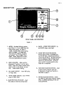
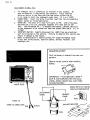
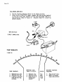
DESCRIPTION
FRONT PANEL AND CONTROLS
FIGURE I
I •
e
.
4_
e
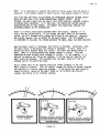
METER. Provides following scales-
Low Ohms X 1, 0 to 1,000 Ohms (10
Ohms center scale), HI Ohms X
1,000, (10,000 Ohms center scale)t
RPM Hi 0-6000, Lo 0-1200 RPM,
Volts 0-i6 Lo, 0-32 Hi. Dwell 8
cyl. _)-45 a , 4 cy!. 0-90 °, 6 cyl.
0-60 , Amps, Parers 0-3.2 Volts1
AIte rnator-good/defective zones.
ZERO ADJUSTER. Meter painter
adjustment, if pointer is not on zero,
slowly rotate this plastic slotted screw
right or left to set pointer on zero
line. Check before testing.
RED AMPS SOCKET. Insert RED plug
on Amps lead.
WHITE OHMS SOCKET. Insert WHITE
plug on Ohms lead.
BLUE RPM PICK UP SOCKET. Insert
Blue plug on inductive pickup lead.
6. BLACK - OTHER TESTSSOCKET. In-
sert BLACK plug on test lead.
•
OTHER TESTS SELECTOR SWITCH.
Always place switch In CENTER posi-
tion for all tests, indlcoted by functlon
switch (No.B) above. Use left hand posl-
tlon for charging Amps and right hand
positton for starting Amps. ALWAYS
return switch to center posltlon when
Amp$ test is completed.
. FUNCTION SELECTOR SWITCH. Used
to select meter range for each test.
A description of each test function is
described on page 4.
. RANGE SELECTOR SWITCH. Select
for HIGH or LOW scale range for VOLTS,
RPM, or OHMS depending on the test
being performed.

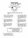
Function Selector
Alternator RPM InducttveTach
m m D
Volts__, well
Points m _ Ohms
FUNCTION SELECTOR SWITCH POSITIONS
FIGURE 2
m
POINTS. 3.2 Volt Lo scale-provldes
point condition on scale. Also used
for locating voltage drops in elect..
rlcal starting and charging system.
VOLTS. Used to Indicate battery
charging and starting cor_ditlons.
Use 16volt Lo scale for t2 volt systems_
and 32 volt (HI) r_ale for 24 volt
systems•
4. RPM. Provides i200 or 6000 RPM
engine speed reading. See item #9
Page 3. Use Lo-i200 RPM range fat
all Lo speed carburetor idle tests
and Hi- 6000 RPM range for high
speed tests.
5. DWELL. Used to check point dwell
on breaker polnt ignitton systems.
Read 45 ° scale fo[ 8 cvi.o 60 ° scale
for 6 cyl, and 90" scale for 4 cyt.
engines.
. ALTERNATOR. Indlcates alternator
condition on GOOD or DEFECTIVE
sca'te wlth englne running. It w(ll
detect open or shorted diodes or
windings.
.
OHMS. HI & Lo - used to measure
electrical resistance in Ohms, on
ignition cables, ballast resistOrSeor
ignition coil windings. Select HI or
Lo position. See Item 19 Page 3.
.................................................. i i i iiillll illrlll[ i iii ii ...................................................
IMPORTANT: The above function tests will
NOT WORK on meter unless other
tests selector sw(tch4, ITEM
Nc. 7 Page No. 3) Is in CENTER
POSITION for OTHER TESTS.
NOTE: The Ohms test operates from an
internal 9 volt battery and ;ncorperates
automatic Internal zero calibration.
No external zero adjustment ;s required.

I.
2_
.
d
5_
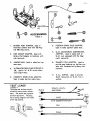
IGNITION J
KIT
ACCESSORIES
FIGURE 3
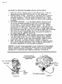
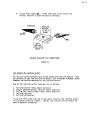
BATTERY POST ADAPTER. Used in
electrical systems tests with i00 Amp
and 400 Amp shunts.
SIDE MOUNT ADAPTER. Used with
Battery Post Adapter on batteries with
side terminals.
JUMPER LEAD. Used in electrical sys-
tems tests.
ALTERNATER FIELD PLUG CONNECT-
OR. Used in "A" & "B" circuit alter-.
nator output tests.
DOMESTIC SPARK PLUG ADAPTER.
Used to make ignition cable tests.
4t FOREIGN SPARK PLUG ADAPTER.
Used to make ignition cable tests.
.
G.M. DIAGNOSTIC CONNECTOR.
ADAPTER. Used to make tests on
G.M. cars equipped with the diag-
nostic connector.
PRIMA!RY COIL ADAPTER. Used to
provide easy hook-up on ignLtion sys-
tems with insulated call primary con-
necHons.
9_
H.E.i. ADPTER. Used to provide
Dwell connection on G.M.H.E.I.
systems.
................................................ ' .......................... _'_ ..................... Itrtrnlnrlrllllllrlrlll .................................................................................................
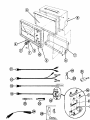
TEST LEADS
FIGURE 4
The plugs and socketsare pol-
arized to insure correct attach-
ment. The socket has a groove
on each top corner. The plug
has a mating ridge on the inside
of the top corners.
LEAD _ PANEL
PLUG k_ SOCKET
BLACK
RED
BLUE
POINTS, VOLTS, j _m,._
AND DWELL ..................._.,_,,_ _,_
AMPS ....
r* _"b'_WITH '-'_':::':'100/400.......AMP"' _'SHUNT'" _-- I_€;
RPM
WHITE
_m,.. OHMS

v_,a_,.,/l_ll_lr'1_,. I IUI_I_'.'_ run r-t_l_C.lll_iL I r..,.._ t O
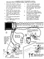
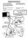
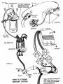
BREAKER POINT CONVENTIONAL IGNITION SYSTEMS
I,, METER ZERO ADJUSTER. Before con-
necting any test leads, always check
meter po_nter zero position, if not on
zero, slowly rotate adjuster with pro-
per size flat screwdriver and set point-
er on zero line.
2. LEADS. insert all three test leads
into matching color sockets on panel.
Connect leads as illustrated below.
3. Install battery post adapter on the
negative ground battery terminal as
shown.
4, Connect RED clip to battery positive
(+) termlnal,
5. Connect BLACK clip to battery neg-
atlve (-) GRD terminal,
6_
,
,
9.
10.
Connect the GREEN clip to the dis,.
tr_butor termlnai on call primary.
Attach RPM induction pickup to a
spark plug cable as close to dlstrtbu-
tar cap as possible. ,Jaws must be
fuliy closed.
DO NOT cc_nect OHMS clip.
I
Engine must be at operating tempera-
ture before testing, Proceed with tests
as outt_ed in this manual.
Starter Amp shunt must remain closed
at all times except for charging sys-
tem test as indicated. Damage to
Battery Adaptor can occur if the
above instruction is not followed,
CLOSE STARTER
SHUNT FOR
STARTERAMPS
OPEN FOR
CHARGING
AMPS
®
RED
JAWS MUSTCLOSE SO UPPERAND LOWER yPLUG
PoLEP,ECESTOUt. ACH'o'r.ER®
TACH PICK-UP MUST BE AS
CLOSE TO DISTRIBUTOR CAP
AS POSSIBLE
WIRE TO E
THIS GAP
tEEN
TO GROUND
ON ENGINE
iSE NUTS MUST
_-_ BETIGHTENED WITH
A WRENCH.
TI EN
THIS SCREW
I'O STARTER AND ALTERNATOR
FIGURE
RED
SCREW POST INTO BATTERY
TERMINAL BEFORE INSTALLI
BATTERY POST ADAPTER,

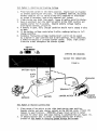
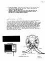
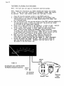
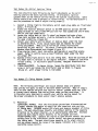
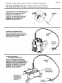
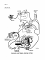
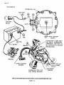
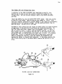
CONNECTIONS FOR ENGINE TESTS
ELECTRONIC IGNITION SYSTEMS
Connect test leads as instructed on
previous page for BREAKER POINT
systemsand as illustrated below with
the following exception; See Test Number
15 far proper connection of the GREEN
clip.
Proceed with tests as outlined in this
manual--Oral fling those testswhich
apply only to BREAKERPOINT SYSTEMS
Engine must be at operating temperature
before testing.
Always close starter shunt b6fore
starting engine.
SEE PAGE No. 6 FOR NUMBER IDENT-
IFICATION.
_PLUG WIRE TO BE
®
JAWS MUST CLOSE SO UPPERAND LOWER
POLE PIECES TOUCH EACH OTHER
i
BLUE
RED
_LACK
CLAMP TACH PICK-UP MUST BE
CLOSE TO DISTRIBUTOR CAP AS
POSSIBLE
®
IEEN
CLOSESTARTE_SHUNT
FORSTARTERAMPS
OPENFORCHARGING
AMPS_.__
See Test
Numbe r 1.5for
connection
)BLACK
DISTRIBUTOR
STRIBUTOR MAGNETIC
_ICK-UP CONNECTOR.
®
GROUND
ON ENGINE
NUTS MUST
BETIGHTENED WITH
EN A WRENCH.
THIS SCREW
STARTER AND ALTERNATOR

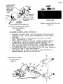
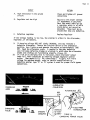
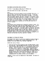
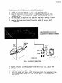
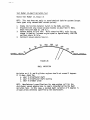
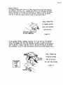
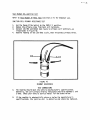
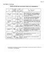
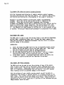
Test Number 1--Startin_ and Crank ing_Vg.!tage,
I. Place function switch in the VOLTS position. Engine must be disabled
to prevent Starting for this test. On ELECTRONIC IGNITION, disconnect
battery cable at coil or unplug pickup coil connector at distributor
or ground HT secondary lead on any external coil system. ,
2. Close starter amp shunt (See page 6, Figure 6) before operating starter.
3. Have an assistant turn the ignition switch to the START position and
operate starter for 15 seconds. Observe battery voltage reading
with engine cranking, (Figure 8).
4. A battery in good, fully charged condition should read a steady 9 volts
or more.
5. If the battery voltage reads below g volts, recharge battery to full
charge condition.
6. Excessive fluctuating voltage reading (over i volt) can be caused
by a starter in poor condition due to worn bearings, dirty commutator,
a defective battery or corroded starter cables, Clean, tight connec-
tions are a must throughout the starter system.
BA TTERY V OLTS
BLACK
CLIP
RED
CLIP
STARTING AND CRANKING
VOLTAGE TEST CONNECTIONS
FIGURE B
L
SOLENOID
TERMINAL"S"
GR BATTERY STARTERMOTOR ENGI NE
)UND
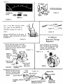
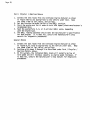
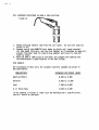
Test Number_2-,Starter Current Draw
I. Place center slide switch to the right hand starter amps position.
Operate starter and note starter current on the 400 Amp scale, (Figure 10),
Compare to specifications. IMPORTANT--Always return switch to center
position for other tests when amps reading is compieted{AZ_o _¢e F_gu_e 15J.
2. If battery-starter test is normal (a steady reading over 9 volts),
proceed to Test Number 4_Cha_gingS_stemVg]tage and Current.

Page 9
CLOSE STARTER
SHUNT FOR
STARTER AMPS
OPEN FOR
CHARGING
AMPS
BLACK
v
RED
TO GROUND
ON ENGINE
NUTS MUST
BETIGHTENED WITH
A WRENCH.
TIGH!
v THIS SCREW
STARTERAND ALTERNATOR
Conn_c_on_ For S_J_uzt_.ng il C,ho_rg_ng
CuArent Measurements
FIGURE g
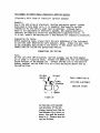
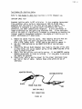
Test Number 3--Starter Circuit Voltage_..Loss
STARTERAMPS
S_t_ C_r{nt .,c_it_h Po_Z_Zon
FIGURE 10
I. Disconnect all tester leads. Use only the BLACK PLUG battery-dwell
lead for this test. Use the BLACK and GREEN test clip for voltage
loss tests.
2. Place function switch in POINTS position and read 3 volt points
scale. Each division is .I volt.
3. Disable engine to prevent starting by grounding HV iead of the coil
as shown below. On HEI or electronic systems disconnect battery
lead at coil or unplug distributor pickup coil connector.
4. Refer to starter system illustrated below. Connect GREEN and BLACK
clips across each section of circuit shown by numbers (i-2-3-4 etc.).
5. All readings must read .2 volts (2 div) or less for normal conditions.
Reverse test leads if meter reads backwards.
6. High readings will be caused by corroded or loose connections at
battery terminals, cables or a worn solenoid.
Connect_Lon,s For Vo.&_ge
Lo_S M_asu_r_ments
FIGURE 11
®
®
STARTER

va_ iu
7, Remove and clean battery terminals and cable terminals in a warm
water solution with baking soda to dissolve corrosion, Tighten nuts
on starter solenoid terminals. Readings below B volts at the starter
usually indicate a defective starter cable or burned solenoid con-
tacts. Replace defective parts as required for good starter per-
formance.
8. Replace worn or corroded cables as required to correct condition.
g. Do not crank for mor_ than 15 seconds at a time, Allow starter
motor to cool off for 30 seconds between tests,
10. When tests are completed, reconnect coil for normal starting.
The function of the charging system is to keep the battery In an optimum
state of charge, to provide the necessary current to start the engine,
and operate the electrical systems when the engine is running. The
battery is charged by an alternator that is driven bye belt connected
to a pulley on the engine crankshaft. The alternator generates an alter-
nating current (A, C. ) that is converted by internal diodes Into direct
current (D. C,) to charge the battery, A regulator is needed in the
charging system because the alternator output voltage increases as the
engine speed increases, The regulator keeps the alternator output voltage
at a safe upper limit so the battery will not be overcharged and the
headlights and accessories will not be damaged by excessive voltage.
I. Place function switch in the VOLTS position. The Center Slide Switch
must be in the OTHER TESTS position.
2. Slide the RANGE SELECTOR switch to the LOW range(O-16 volts) for
12 volt systems or to the HIGH range (0-32 volts) for 24 volt sy-
stems. Read test results on the appropriate VOL_S scale.
3. Be sure the shunts are in position on the Battery Amps Adapter as
shown in Key No.I Page 5, before starting the vehicle.
CAUTION: TIGHTEN ALL NUTS ON THE BATTERY ADAPTOR FIRMLY WITH A WRENCH
TO AVOID EXCESSIVE HEAT AND POSSIBLE SHUNT DAMAGE.
4. Before performing Step 5, start the engine and allow it to run for
10 to 15 minutes or until the engine compartment is warm, then shut
it off. In order to obtain proper results from this test, the
battery must be partially discharged. To accomplish this, switch
on the headlights and put the blower on HIGH for a minimum of one
minute, or remove the distributor wire to prevent the car from
starting and crank the engine for about 30 seconds, then follow step 5,
5, Start the engine. Operate at a fast idle (approximately 1500 RPM).
Open the starter amps shunt. Note the battery charging voltage. The
meter should read over 12 volts and slowly rise to regulated voltage
in a few minutes (15 I/2 volts maximum).(Figure 12)
6. Move the Center Slide Switch to the CHARGING AMPS position and note
the alternator charging rate compared to vehicle specifications.(Figure 12)
Shortly after starting, an alternator in good condition should charge
from 50 to 80% of its rated capacity, and slowly decrease as the
battery regains its charge. The charging voltage will slowly rise
as the ampere rate decreases and maximum regulated voltage Is obtained.
7. Move the Center Slide Switch tO the OTHER TESTS position again for
voltage reading and operate the engine at fast idle until the
charging voltage stops increasing. Note the maximum voltage and compare
to vehicle specifications.
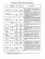
8. If the charging voltage exceeds IB I/2 volts or as specified, replace
or adjust the voltage regulator. If the voltage reading is too high,
the defect could be:

Page 11
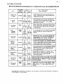
DEFECT
ACTION
A. High resistance in the ground
circuit
Clean and tighten all ground
connections
B. Regulator set too high
Adjust to the proper setting
(If adjustment is possible)
Most late model vehicles use
a regulator which is of solid
state design and cannot be
adjusted. These must be re-
placed when they are defective,
C. Defective regulator
Replace Regulator
if the voltage reading is too low, the problem is either in the alternator,
regulator, or the battery.
9. If charging voltage DOES NOT slowly INCREASE, this may indicate a
defective alternator. Rotate the Function Switch to the alternator
position, turn lights on and operate the engine at approximately 1200
RPM. Read the aiternator scale. A reading in the gray defective
zone indicates defective diodes or windings in which case the alternator
diodes and windings are functloningproperly.(Figure 12).
10. If a low or no charging rate is indlcated, check alternator output
under full field conditions by removing voltage regulator control
action. (See pages 12& 13 for connections.) To apply full field
voltage for maximum output, refer to vehicle specifications to
determine whether type "A" or "B" system is used for proper field bypass
connections.
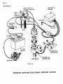
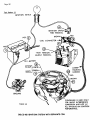
CHARGING
AMPS
ALTERNA TOR
om,w_,m CONDITION
V
RED
CLIP
ALTERNATOR
BLACK
CHARGING
V OLTS
ENGINE
GROUND
WIRES
VEHICLE TO REGULATOR
12 VOLT
BATTERY FIGURE 12
"J_'/ CHARGING AMPS & VOLTS

Page12
CHARGING ot_,r_
V
AM ,s gill
FIGURE 13
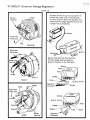
NOTE: If the AMPS indicates below
zero (left) during CHARGING or
STARTING, reverse the leads as
shown,
Caution: DO NOT pull on the wires, if
necessary_ grasp the terminal with pliers
tO remove it,
FIGURE 15
Remove field lead (green wire) from
the alternator field terminal. Connect
iumper wire from the alternator field
terminal to ground.
Remove
Field Lead
(Green
Wire)
Battery
Output
Terminal
Plug
Field Terminal
(Horizonhal)
Jumper
Connect Jumper
CHRYSLER to ground
FIGURE i7 A
Field Terminal
(Vertical)
(Blue Wire)
JJL ...... _.....................
Remove cap from the field Stator
terminal. Connect jumper Terminal
wlre to field terminal and !
ground. Ground Terminal
FIGURE 17 C
Field Term;hal
Regulat_
Terminal
IIATTERY _ft AOAPTI[R CONN-
tCtlONS ItOlt ALTERNATOR Tilt
FIGURE 14
FIGURE 16
"A" CIRCUIT
(Electronic Voltage
Regulator)
Insert screwdriver not more than I
inch in end frame hole, ground tab
to frame with screwdr;ver. No
additional adapter is needed.
DELCO
FIGURE 17 B
Tab
End
Frame
Hole
\
Remove Cap
INTEGRAL DESIGN
FORD Regulator Exclte' Terminal
(to Ignition Switch)
Ground with
Jumper Wire

i'_e 13
"B" CIRCUIT ( External Voltage Regulator)
FIGURE 18
.................................................... II II]llllllnll I IIIIIIIIII II ................. r
Battery Jumper
Term _nol
Plug
CHRYSLER
bisconnect
F_eld Lead
Te _1
DELCO
Jumper
Stator _"_\ /
Di,conoe=t/ __./7,_
F;et
Gr°umd__B_attery
FORD Term;hal
........................................................................ 1111111111111111111111111111111111"
On some vehicles if may be inc_onvenlent to
connect the iumper wlre at the alternator.
Imsuch a iftuaHon remove the regulator con-
nector from the voltage regulator and €onnect
a iumper wire as illustrated.
ignition
Remove field lead from field terminal.
Connect iumper w_re from positive
terminal of battery to the field lead.
Battery,
Ignition Switch
Jumper
Batter
Regulator
Commector
Field
Field Stator

ru_E _
I. Be sure the shunts are tightly secured to the Battery Amps Adaptor
as shown in Key No. I Page 5 , and the Function Selector Switch is
placed in the Alternator position.
CAUTION: TIGHTEN ALL NUTS ON THE BATTERY ADAPTOR WITH A WRENCH TO
AVOID EXCESSIVE HEAT AND POSSIBLE SHUNT DAMAGE. IF YOU ATTEMPT TO
START THE ENGINE WITH THE SHUNT DISCONNECTED, THE 1/40HM RESISTOR
MOUNTED ON THE BATTERY ADAPTOR MAY BLOW OUT.
2. Start the engine, then carefully disconnect the slotted ends
of the shunts as shown in the figure below. Turn the headlights
on and operate the engine at approximately 1200 RPM and observe the
alternator condition scale.
3. A reading in the RED GOOD ZONE on the meter indicates that the
alternator windings and diodes are satisfactory.
4. A reading in the GRAY DEFECTIVE ZONE indicates that one or more
diodes are open or shorted or that the stator winding is open or
shorted to ground or has shorted turns. Refer to Tests 9 and 10
Alternator Diode, Statorand Rotor Tests for further testing.
IMPORTANT: Refer to vehicle specifications to determine whether type
"A" or type "B"system is on the vehicle, Also check the rated output of
alternator on the nameplate or specifications listing,
1. To perform this test, it is necessary to ground the field in the
type A Circuit or remove the regulator from the charging system and
energize the field in the Type B Circuit. This provides full field
operation and the alternator will charge at its maximum rated capacity,
2. Place the FUNCTION SELECTOR Switch in the VOLTS position and slide
the Center Slide Switch to the AMPS CHARGING position.
3, On the Type A Circuit, ground the field as shown on page 12, proceed
with Step 5 below.
4. On the Type B Circuit, disconnect the wiring harness plug from the
regulator and energize the field as shown on page 13.
5. Before starting the vehicle, be sure the shunts are connected to the
Battery Amps Adapter as shown in Key No. I on page 5 • Turn
on the headlights and set blower speed to high. The meter should
read to the left of zero or "backwards". If it reads up scale, re-
verse the shunt connections as shown in Figure 1 5.
Turn all lights and accessories "OFF". Start the engine and operate
it at the speed recommended by the manufacturer for alternator
output test. Unless otherwise specified, adjust engine speed as follows:
Chrysler 1250 RPM
GM-Delco-Remy 2500 RPM
Ford 2900 RPM

Page 15
With the engine running, carefully open the starter shunt as shown
in Key 10 on page 6 . Observe the current (amps) reading on the
0-100 Amps scale, reduce engine speed to curb idle and compare meter
reading with the manufacturer's specifications.
ALTERNATOR FULL FIELD
NOTE: To determine the actual output current, add 5 amperes to the meter
reading obtained during the output test. This is the approximate current
used by the ignition system, dash instruments and alternator field toll
combined which does not reach the battery to be measured during
this test. If the meter reading is at or higher than specified, the
alternator output is satisfactory. If the meter reading Is less than
specified, a loose or worn alternator drive belt, a faulty field or
battery wire to the alternator, or a poorly grounded or defective alternator
is indicated. If the meter reading is to the left of zero, a broken
field wire or a defective alternator is indicated. (Meter reading is the
battery discharge current used by the ignition system and dash instruments.)
6. When test is completed, shut off the engine, disconnect jumper lead,
remove the shunt, and reconnect wiring harness plug, connector or
field wire to the regulator for normal operation,
Repeat Test Number 4:±Charging System Vp]tage and Current
If the voltage reading is within the range as specified by the vehicle
service manual, (typically between i3.8 and 15.2 volts on 12 volt systems,
and 27.6 and 30.4 on 24 volt systems) the regulator is satisfactory.
If the voltage reading is out of specifications but satisfactory
operation was obtained on the CHARGING SYSTEM VOLTAGE AND CURRENT and
ALTERNATOR CONDITION tests, the voltage regulator should be adjusted
(if possible) or replaced.
Test Number B--Battery
Repeat Test Number4-,ChargingSystemvo]tage and Current
After the VOLTAGE REGULATOR--TEST 7 is completed, the regulator should
be functioning satisfactorily, leaving the battery as the only untested
component remaining in the CHARGING SYSTEM. To test battery condition,
attach the shunt to the BATTERY POST ADAPTER (Key I Page 5 ), start
the engine, and operate it at approximately 1200 RPM. If the voltage
reading is less than 13.8 volts, check the water level in the battery and
fill to the proper level, if necessary. Charge the battery and repeat
this test. if the voltage reading is still low, the battery is defective
and should be replaced.

Page 16
Test Number 9--Ohms Test
1. The ohmmeter test is powered by an internal 9 volt battery. No
zero calibration is required by the operator. Place Function
Selector Switch in the Ohms position and select either the Hi
or Lo range to match the component under test. (X i or X lOOd)
2. CONNECTIONS: Insert the white Plug Ohms Lead into the corresponding
tester socket as illustrated below.
3. OPERATION: The meter will read full scale at INF. with cllps,open,
and when the clips are connected together will read zero on the
left. (See Paragraph #6.) To measure resistance, connect the clips
to the component to be tested and read the prope_ Ohms scale. (X 1 or
x 1ooo)
4. IMPORTANT CAUTION: ALWAYS disconnect ALL L£ADS from any electrical
part to be tested on the vehicle. Failure to observe this caution may
result in damage to the tester.
5. Refer to manufacturer's specifications for normalresistance value
of any part being tested, ignition cables, ballast resistor, coil
windings, etc.
WHITE PLUG
FIGURE 19
OHMMETERCONNECTIONS
RED
OHMMETER BATTERY
The 9 volt battery ts located in the rear com-
partment,
Observe correctt polarity when installing
battery.
IMPORTANT: 9 VOLT BATTERY ( SEARS#
64i7) IS NOT SUPPLIED WiTH THIS ANA-
LYZER.--OHMS CIRCUIT WILL NOT WORK
WITHOUT BATTERY.
I i
SECONDARY
OHMS
OHMS TESTS ON VARIOL
VEHICLE COMPONENTS
PRIMARY
OHMS
1
FUSE
BLACK
BA LLAST RESISTOR
COIL

Page 17
6. BATTERY REPLACEMENT. When the g volt battery is low, the meter will
not read full scale with the clips open. Replace the battery to
obtain accurate OHMS measurement.
7. IMPORTANT: When the tester is not in use or when Ohms tests are
completed ALWAYS turn the Function Selector Switch OUT of the
Ohms position to prevent battery discharge.
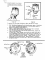
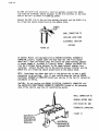
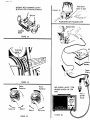
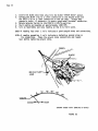
DIODE TESTS ON OHMS X 1000 POSITION
Alternator diodes in a disassembled alternator can be tested for "shorts"
or "opens" with the stator leads disconnected as illustrated. To
facilitate checking the diodes in the end frame and heat sink, place a short
length of wire or nail in the jaws of the RED and BLACK test clips as shown
in the illustration. Touch the RED lead to the diode case and the BLACK
lead to the diode lead as illustrated in Step A and note the meter reading,
Reverse the lead connections on the same diode and again note the reading
as in Step B. A good diode will have one low and one high reading, if
both readings are very low, or if both readings are very high, the diode is
defective and should be replaced.
WHITE PLUG
FIGURE 20
RED
RED
Initial Connection
STEP
LACK
ALTERNATOR DIODE TESTS

See steps 1-7 TestNumberg--OhmsTest for Ohmmeter use
ROTOR AND STATOR TESTS ON OHMS X 1000 POSITION
Rotor--
The alternator rotor may be tested for open or grounded field coils. To
check for opens, touch the test leads to each slip rJng. If the meter
reading is near zero, (left end) the winding is not open. If the meter
shows high reading (extreme right end of the scale), the winding is open
and the alternator should be repaired or replaced. To check for grounds,
touch the test leads from either sllp ring to the rotor shaft or to the
rotor poles. If the meter shows only a slight reading or none at all,
the field winding is not grounded. If the meter reading is near zero
(left end), the winding is grounded and the alternator should be re-
paired or replaced.
Stator--
The alternator stator windings may be checked for grounds or opens. Dis-
connect the three stator leads from the diodes before any test. To check
for opens, successively connect the tester leads between each pair of
stator leads. In each case, if the meter reading is near zero (left end),
the windings are not open. If the meter shows a high reading, the winding
is open and the alternator should be repaired or replaced. To check for
grounds, connect the tester leads to each stator lea_ and to the frame.
If the meter shows a full scale reading, the stator is not grounded, if
the meter is near zero (left end), the stator winding is grounded to the
frame and the alternator should be repaired or replaced.
The purpose of this test is to confirm the presence of supply voltage to
the positive (+) or Battery (Bat) terminal of the Ignition Coil. NO
VOLTAGE AT THIS POINT RESULTS IN A "NO START" CONDITION,
Perform this test as follows:
lm
2.
Place the Function Selector Switch of your Craftsman Analyzer in the
VOLTS position. Place the RANGE SELECTOR in the 0-16 volts position.
Insert the BLACK OTHER TESTS lead in its corresponding socket on the
Analyzer. Connect the BLACK clip to a good vehicle ground such as
the engine block or negative (-) battery post. Connect the RED
clip to the to the positive (+) or battery_at) terminal of the i__R-
nition coil. In the case of the General Motors HEI Syste_,,disconnect
_-e_Tn_ttery (Bat) lead at the Distributor (on Integrai Coil
Systems) or at the coll (on External Coil Systems). Insert the GM
Diagnostic Connector, Page 5 , Key No, 7 into the socket of this
disconnected wire and connect the RED clip to the adaptor.
IMPORTANT: DO NOT ALLOW THIS CONNECTION TO TOUCH GROUNDI THE GREEN CLIP
IS NOT USED.
Page is loading ...
Page is loading ...
Page is loading ...
Page is loading ...
Page is loading ...
Page is loading ...
Page is loading ...
Page is loading ...
Page is loading ...
Page is loading ...
Page is loading ...
Page is loading ...
Page is loading ...
Page is loading ...
Page is loading ...
Page is loading ...
Page is loading ...
Page is loading ...
Page is loading ...
Page is loading ...
Page is loading ...
Page is loading ...
Page is loading ...
Page is loading ...
Page is loading ...
Page is loading ...
Page is loading ...
Page is loading ...
Page is loading ...
Page is loading ...
Page is loading ...
Page is loading ...
Page is loading ...
Page is loading ...
Page is loading ...
Page is loading ...
Page is loading ...
Page is loading ...
Page is loading ...
Page is loading ...
Page is loading ...
Page is loading ...
Page is loading ...
Page is loading ...
-
 1
1
-
 2
2
-
 3
3
-
 4
4
-
 5
5
-
 6
6
-
 7
7
-
 8
8
-
 9
9
-
 10
10
-
 11
11
-
 12
12
-
 13
13
-
 14
14
-
 15
15
-
 16
16
-
 17
17
-
 18
18
-
 19
19
-
 20
20
-
 21
21
-
 22
22
-
 23
23
-
 24
24
-
 25
25
-
 26
26
-
 27
27
-
 28
28
-
 29
29
-
 30
30
-
 31
31
-
 32
32
-
 33
33
-
 34
34
-
 35
35
-
 36
36
-
 37
37
-
 38
38
-
 39
39
-
 40
40
-
 41
41
-
 42
42
-
 43
43
-
 44
44
-
 45
45
-
 46
46
-
 47
47
-
 48
48
-
 49
49
-
 50
50
-
 51
51
-
 52
52
-
 53
53
-
 54
54
-
 55
55
-
 56
56
-
 57
57
-
 58
58
-
 59
59
-
 60
60
-
 61
61
-
 62
62
-
 63
63
-
 64
64


Craftsman 161.210400 Owner's manual
- Category
- Multimeters
- Type
- Owner's manual
- This manual is also suitable for
Ask a question and I''ll find the answer in the document
Finding information in a document is now easier with AI
Other documents
-
Western Speed Control Installation guide
-
C.E. Niehoff & Co N1224 Troubleshooting guide
-
Energizer Pro 4 User manual
-
Innova 5568 Owner's manual
-
AUTO METER BVA-34 User manual
-
-
Jegs 40752 User manual
-
-
Uni-Trend UT105 Specification
-