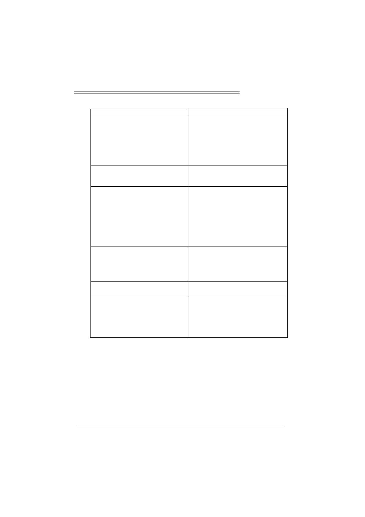
Biostar VIOTECH 3200+ User manual

Category
Motherboards
Type
User manual

Biostar VIOTECH 3200+ is a versatile motherboard that supports a wide range of components and offers a variety of features for both basic and advanced users. With its VIA C7-D or Nano processor and support for up to 8GB of DDR3 memory, it can handle everyday tasks with ease. It also includes integrated graphics, allowing for basic multimedia capabilities without the need for a dedicated graphics card. Additionally, the motherboard has multiple expansion slots, including PCI and PCI Express, for adding additional components such as a sound card or network card.

Biostar VIOTECH 3200+ is a versatile motherboard that supports a wide range of components and offers a variety of features for both basic and advanced users. With its VIA C7-D or Nano processor and support for up to 8GB of DDR3 memory, it can handle everyday tasks with ease. It also includes integrated graphics, allowing for basic multimedia capabilities without the need for a dedicated graphics card. Additionally, the motherboard has multiple expansion slots, including PCI and PCI Express, for adding additional components such as a sound card or network card.

Viotech 3200+ Setup Manual
FCC Information and Copyright
This equipment has been tested and found to comply with the limits of a Class
B digital device, pursuant to Part 15 of the FCC Rules. These limits are designed
to provide reasonable protection against harmful interference in a residential
installation. This equipment generates, uses, and can radiate radio frequency
energy and, if not installed and used in accordance with the instructions, may
cause harmful interference to radio communications. There is no guarantee
that interference will not occur in a particular installation.
The vendor makes no representations or warranties with respect to the
contents here and specially disclaims any implied warranties of merchantability
or fitness for any purpose. Further the vendor reserves the right to revise this
publication and to make changes to the contents here without obligation to
notify any party beforehand.
Duplication of this publication, in part or in whole, is not allowed without first
obtaining the vendor’s approval in writing.
The content of this user’s manual is subject to be changed without notice and
we will not be responsible for any mistakes found in this user’s manual. All the
brand and product names are trademarks of their respective companies.
Table of Contents
Chapter 1: Introduction ........................................ 1
1.1 Before You Start ................................................................................ 1
1.2 Package Checklist............................................................................. 1
1.3 Motherboard Features...................................................................... 2
1.4 Rear Panel Connectors ..................................................................... 3
1.5 Motherboard Layout......................................................................... 4
Chapter 2: Hardware Installation .......................... 5
2.1 Installing Central Processing Unit (CPU)....................................... 5
2.2 FAN Headers...................................................................................... 5
2.3 Installing System Memory................................................................ 6
2.4 Connectors and Slots ......................................................................... 8
Chapter 3: Headers & Jumpers Setup .................. 11
3.1 How to Setup Jumpers .................................................................... 11
3.2 Detail Settings.................................................................................. 11
Chapter 4: Useful Help ........................................ 15
4.1 Driver Installation Note.................................................................. 15
5.2 Extra Information............................................................................ 16
5.3 Troubleshooting............................................................................... 17
Appendix: SPEC In Other Languages ................... 18
German.................................................................................................................. 18
French .................................................................................................................... 20
Italian..................................................................................................................... 22
Spanish ................................................................................................................... 24
Portuguese ............................................................................................................ 26
Polish...................................................................................................................... 28
Russian ................................................................................................................... 30
Arabic..................................................................................................................... 32
Japanese ................................................................................................................ 34
Viotech 3200+
1
CHAPTER 1: INTRODUCTION
1.1 B
EFORE YOU START
Thank you for choosing our product. Before you start installing the
motherboard, please make sure you follow the instructions below:
Prepare a dry and stable working environment with
sufficient lighting.
Always disconnect the computer from power outlet
before operation.
Before you take the motherboard out from anti-static
bag, ground yourself properly by touching any safely
grounded appliance, or use grounded wrist strap to
remove the static charge.
Avoid touching the components on motherboard or the
rear side of the board unless necessary. Hold the board
on the edge, do not try to bend or flex the board.
Do not leave any unfastened small parts inside the
case after installation. Loose parts will cause short
circuits which may damage the equipment.
Keep the computer from dangerous area, such as heat
source, humid air and water.
Do not squeeze or touch CPU Cooler (Fan/Heatsink)
The operating temperatures of the computer should be
0 to 45 degrees Celsius.
1.2 PACKAGE CHECKLIST
Rear I/O Panel Shield X 1
Fully Setup Driver CD X 1 (full version manual files inside)
Serial ATA Cable X 2
Quick Installation Guide X 1
Motherboard Manual
2
1.3 MOTHERBOARD FEATURES
SPEC
CPU VIA C7-D 1.8G Processor
NanoBGA2
VIA CPU On-board
Execute Disable Bit
FSB VIA V4 BUS 800MHz
Chipset VX900
Graphics Chrome9 HD
Max Shared Video Memory is 512MB
Support DirectX 9.0 and Pixel Shader (SM2.0)
Super I/O ITE 8728
Low Pin Count Interface
Environment Control
H/W Monitor
Fan Speed Controller
Main
Memory
DDR3 Slots x 2
Each DIMM supports 512MB/1GB/2GB/4GB DDR3
Max Memory Capacity 8GB
Supports DDR3 800 / 1066
Sing le C hann el Mode DDR3 memory modu le
Registered DIMM and ECC D IMM is not supported
SATA Integrated Serial ATA Controller
Data transfer rates up to 3.0 Gb/s.
SATA Vers ion 2.0 specificat ion co mp liant.
LAN Realtek RTL8103EL 10 / 100 Mb/s auto negotiation
Sound
Codec
VIA VT1708S
5.1 channels audio out
High-Definition Audio support
PCI slot x1 Supports PCI expansion card
Slot
PCI Express Gen2 x 16 slot x1 Supports PCI-E x16 expansion card (x8-Lane only)
SATA Connector x2 Each connector supports 1 SATA devices
Front Panel Connector x1 Supports front panel facilities
Front Audio Connector x1 Supports front panel audio function
CPU Fan Header x1 CPU Fan power supply
On Board
Connector
System Fan Header x1 System Fan Power supply
Viotech 3200+
3
SPEC
Clear CMOS Header x1 Restore CMOS data to factory default
USB Connector x2 Each connector supports 2 front panel USB ports
Printer Port Connector x1 Each connector supports 1 Printer port
Serial Port Connector x1 Connects to RS-232 Port
Power Connector (24pin) x1 Connects to Power supply
Power Connector (4pin) x1 Connects to Power supply
Real Panel
I/O
PS/2 Keyboard x1
PS/2 Mouse x1
VGA Port x1
LAN Port x1
USB Port x4
Audio Jack x3
Connects to PS/2 Keyboard
Connects to PS/2 Mouse
Connects to monitor
Connects to RJ-45 ethernet cable
Connects to USB devices
Provide Audio-In/Out and microphone connection
Board Size 170 (W) x 220 (L) mm
OS Support
Windows XP / Vista / 7
Biostar reserves the right to add or remove support
for any OS with or without notice.
1.4 REAR PANEL CONNECTORS
PS/2
Mouse
PS/2
Keyboard
USBX2USBX2
LAN
Line In/
Surround
Line Out
Mic In 1/
Bass/ Center
VGA
Since the audio chip supports High Definition Audio Specification, the function of each audio
jack can be defined by software. The input / output function of each audio jack listed above
represents the default setting. However, when connecting external microphone to the audio
port, please use the Mic In (Pink) audio jack.
Motherboard Manual
4
1.5 MOTHERBOARD LAYOUT
KBMS1
VGA1
AUDIO1
RJ45USB1
USB3
CPU_FAN1
JUSBV2
LAN
Codec
F_AUDIO1 J_COM1 J_PRINT1
SYS_FAN1
PEX16_1
PCI1
BAT1
PANEL1
Super
I/O
BIOS
JCMOS1
SATA2
SATA1
F_U SB2
F_USB1
JUSBV1
ATXPW R 1
DIMMA1
DIMMA2
ATXPW R 2
CPU1
VIA
VX900
VIA
C7-D
1.8G
Note: represents the 1
st
pin.
Viotech 3200+
5
CHAPTER 2: HARDWARE INSTALLATION
2.1 I
NSTALLING CENTRAL PROCESSING UNIT (CPU)
The motherboard includes an embedded VIA C7-D or Nano processor,
and a heatsink has been installed to provide sufficient cooling.
2.2 FAN HEADERS
These fan headers support cooling-fans built in the computer. The fan
cable and connector may be different according to the fan manufacturer.
Connect the fan cable to the connector while matching the black wire to
pin#1.
CPU_FAN1: CPU Fan Header
Pin
Assignment
1 Ground
2 Power
3 FAN RPM rate sense
14
4 Smart Fan Control
SYS_FAN1: System Fan Header
Pin
Assignment
1 Ground
2 +12V
13
3 FAN RPM rate
sense
Note:
CPU_FAN1 supports 4-pin head connector; SYS_FAN1, 3-pin head one. When
connecting with wires onto connectors, please note that the red wire is the positive and
should be connected to pin#2, and the black wire is Ground and should be connected to
GND.
Motherboard Manual
6
2.3 INSTALLING SYSTEM MEMORY
A. DDR3 Module
DIMMA1
DIMMA2
1. Unlock a DIMM slot by pressing the retaining clips outward. Align a
DIMM on the slot such that the notch on the DIMM matches the
break on the Slot.
2. Insert the DIMM vertically and firmly into the slot until the retaining
chip snap back in place and the DIMM is properly seated.
Viotech 3200+
7
B. Memory Capacity
DIMM Socket
Location
DDR3 Module
Total Memory
Size
DIMMA1 512MB/1GB/2GB/4GB
DIMMA2 512MB/1GB/2GB/4GB
Max is 8GB.
Motherboard Manual
8
2.4 CONNECTORS AND SLOTS
SATA1/SATA2: Serial ATA Connectors
The motherboard has a PCI to SATA Controller with 2 channels SATA interface,
it satisfies the SATA 2.0 spec and with transfer rate of 3Gb/s.
Pin
Assignment
1 Ground
2 TX+
3 TX-
4 Ground
5 RX-
6 RX+
7
4
1
SATA2
SATA1
7 Ground
ATXPWR2: ATX Power Source Connector
This connector provides +12V to CPU power circuit. Please make sure this
connector has been plugged in perfectly.
Pin
Assignment
1 +12V
2 +12V
3 Ground
1
23
4
4 Ground
Viotech 3200+
9
ATXPWR1: ATX Power Source Connector
This connector allows user to connect 24-pin power connector on the ATX
power supply.
1
12
13
24
Pin Assignment Pin Assignment
13 +3.3V 1 +3.3V
14 -12V 2 +3.3V
15 Gro und 3 Gro und
16 PS_ON 4 +5V
17 Gro und 5 Gro und
18 Ground 6 +5V
19 Gro und 7 Gro und
20 NC 8 PW_OK
21 +5V 9 Standby Voltage+5V
22 +5V 10 +12V
23 +5V 11 +12V
24 Ground 12 +3.3V
PCI1: Peripheral Component Interconnect Slot
The motherboard is equipped with 1 standard PCI slot. PCI stands for Peripheral
Component Interconnect, and it is a bus standard for expansion cards. This PCI
slot is designated as 32 bits.
PCI1
Motherboard Manual
10
PEX16_1: PCI-Express x16 Slot
- PCI-Express 2.0 compliant (x8-Lane only).
- Maximum theoretical realized bandwidth of 4GB/s simultaneously per
direction, for an aggregate of 8GB/s totally.
PEX16_1
Viotech 3200+
11
CHAPTER 3: HEADERS & JUMPERS SETUP
3.1 H
OW TO SETUP JUMPERS
The illustration shows how to set up jumpers. When the jumper cap is
placed on pins, the jumper is “close”, if not, that means the jumper is
“open.
Pin opened Pin closed Pin1-2 closed
3.2 DETAIL SETTINGS
PANEL1: Front Panel Header
This 16-pin connector includes Power-on, Reset, HDD LED, Power LED, and
speaker connections. It allows user to connect the PC case’s front panel switch
functions.
1
PWR_LED
ON / OF F
RST
HLED
SPK
++
+
9
-
-
8
16
+
Pin Assignment Function Pin Assignment Function
1 +5V 9 N/A
2 N/A 10 N/A
N/A
3 N/A 11 N/A N/A
4 Speaker
Speaker
Connector
12 Power LED (+)
5 HDD LED (+) 13 Power LED (+)
6 HDD LED (-)
Hard drive
LED
14 Power LED (-)
Power LED
7 Ground 15 Power button
8 Reset control
Reset button
16 Ground
Power-on button
Motherboard Manual
12
F_USB1/F_USB2: Headers for USB 2.0 Ports at Front Panel
This motherboard provides 2 USB 2.0 headers, providing user to connect
additional USB cable on the PC front panel, and also can be connected with
internal USB devices, like USB card reader.
Pin
Assignment
1 +5V (fused)
2 +5V (fused)
3 USB-
4 USB-
5 USB+
6 USB+
7 Ground
8 Ground
9 Key
1
9
2
10
F_USB2 F_USB1
10 NC
JUSBV1/JUSBV2: Power Source Headers for USB Ports
Pin 1-2 Close:
JUSBV1: +5V for USB ports at front panel (F_USB1/F_USB2).
JUSBV2: +5V for USB ports at USB3/RJ45USB1.
Pin 2-3 Close:
JUSBV1: +5V STB for USB ports at front panel (F_USB1/F_USB2).
JUSBV2: +5V STB for USB ports at USB3/RJ45USB1.
1
3
Pin 1-2 close
1
3
JUSBV1
JUSBV2
1
3
Pin 2-3 close
Note:
In order to support this function “Power-On system via USB device,” user should place
JUSBV1/ JUSBV2” jumper cap on Pin 2-3 individually.
Viotech 3200+
13
F_AUDIO1: Front Panel Audio Header
This header allows user to connect the front audio output cable with the PC front
panel.
Pin Assignment
1 Mic Left in
2 Ground
3 Mic Right in
4 GPIO
5 Right line in
6 Jack Sense
7 Front Sense
8 Key
9 Left line in
10 Jack Sense
19
210
JCMOS1: Clear CMOS Header
Placing the jumper on pin2-3 allows user to restore the BIOS safe setting and
the CMOS data. Please carefully follow the procedures to avoid damaging the
motherboard.
13
Pin 1-2 Close:
Normal Operation (Default).
13
13
Pin 2-3 Close:
Clear CMOS data.
Clear CMOS Procedures:
1. Remove AC power line.
2. Set the jumper to “Pin 2-3 close”.
3. Wait for five seconds.
4. Set the jumper to “Pin 1-2 close”.
5. Power on the AC.
6. Load Optimal Defaults and save settings in CMOS.
Motherboard Manual
14
J_COM1: Serial port Connector
The motherboard has a Serial Port Connector for connecting RS-232 Port.
Pin
Assignment
1 Carrier detect
2 Received data
3 Transmitted data
4 Data terminal ready
5 Signal ground
6 Data set ready
7 Request to send
8 Clear to send
9 Ring indicator
19
210
10 NC
J_PRINT1: Printer Port Connector
This header allows you to connector printer on the PC.
1
2
25
26
Pin Assignment Pin Assignment
1 -Strobe 14 Ground
2 -ALF 15 Data 6
3 Data 0 16 Ground
4 -Error 17 Data 7
5 Data 1 18 Ground
6 -Init 19 -ACK
7 Data 2 20 Ground
8 -Scltin 21 Busy
9 Data 3 22 Ground
10 Ground 23 PE
11 Data 4 24 Ground
12 Ground 25 SCLT
13 Data 5 26 Key
Viotech 3200+
15
CHAPTER 4: USEFUL HELP
4.1 D
RIVER INSTALLATION NOTE
After you installed your operating system, please insert the Fully Setup
Driver CD into your optical drive and install the driver for better system
performance.
You will see the following window after you insert the CD
The setup guide will auto detect your motherboard and operating system.
Note:
If this window didnt show up after you insert the Driver CD, please use file browser to
locate and execute the file SETUP.EXE under your optical drive.
A. Driver Installation
To install the driver, please click on the Driver icon. The setup guide will
list the compatible driver for your motherboard and operating system.
Click on each device driver to launch the installation program.
B. Software Installation
To install the software, please click on the Software icon. The setup guide
will list the software available for your system, click on each software title
to launch the installation program.
C. Manual
Aside from the paperback manual, we also provide manual in the Driver
CD. Click on the Manual icon to browse for available manual.
Note:
You will need Acrobat Reader to open the manual file. Please download the latest version
of Acrobat Reader software from
http://www.adobe.com/products/acrobat/readstep2.html
Motherboard Manual
16
5.2 EXTRA INFORMATION
CPU Overheated
If the system shutdown automatically after power on system for
minutes, that means the CPU protection function has been activated.
When the CPU is over heated, the motherboard will shutdown
automatically to avoid a damage of the CPU, and the system may not
power on again.
In this case, please double check:
1. The CPU cooler surface is placed evenly with the CPU surface.
2. CPU fan is rotated normally.
3. CPU fan speed is fulfilling with the CPU speed.
After confirmed, please follow steps below to relief the CPU
0protection function.
1. Remove the power cord from power supply for seconds.
2. Wait for seconds.
3. Plug in the power cord and boot up the system.
Or you can:
1. Clear the CMOS data.
(See “Close CMOS Header: JCMOS1” section)
2. Wait for seconds.
3. Power on the system again.
Viotech 3200+
17
5.3 TROUBLESHOOTING
Probable Solution
1. There is no power in the system.
Power LED does not shine; the
fan of the power supply does not
work
2. Indicator light on keyboard does
not shine.
1. Make sure power cable is
securely plugged in. (Both
A
TXPWR1 and ATXPWR2 power
connecters are plugged in,
perfectly.)
2. Replace cable.
3. Contact technical support.
System is inoperative. Keyboard lights
are on, power indicator lights are lit,
and hard drives are running.
Using even pressure on both ends of
the DIMM, press down firmly until the
module snaps into place.
System does not boot from a hard disk
drive, but can be booted from optical
drive.
1. Check cable running from disk to
disk controller board. Make sure
both ends are securely plugged
in; check the drive type in the
standard CMOS setup.
2. Backing up the hard drive is
extremely important. All hard
disks are capable of breaking
down at any time.
System only boots from an optical
drive. Hard disks can be read,
applications can be used, but system
fails to boot from a hard disk.
1. Back up data and applications
files.
2. Reformat the hard drive.
Re-install applications and data
using backup disks.
Screen message shows “Invalid
Configuration” or CMOS Failure.
Review system’s equipment. Make sure
correct information is in setup.
System cannot boot after user installs a
second hard drive.
1. Set master/slave jumpers
correctly.
2. Run SETUP program and select
correct drive types. Call the drive
manufacturers for compatibility
with other drives.
  • Page 1 1
  • Page 2 2
  • Page 3 3
  • Page 4 4
  • Page 5 5
  • Page 6 6
  • Page 7 7
  • Page 8 8
  • Page 9 9
  • Page 10 10
  • Page 11 11
  • Page 12 12
  • Page 13 13
  • Page 14 14
  • Page 15 15
  • Page 16 16
  • Page 17 17
  • Page 18 18
  • Page 19 19
  • Page 20 20
  • Page 21 21
  • Page 22 22
  • Page 23 23
  • Page 24 24
  • Page 25 25
  • Page 26 26
  • Page 27 27
  • Page 28 28
  • Page 29 29
  • Page 30 30
  • Page 31 31
  • Page 32 32
  • Page 33 33
  • Page 34 34
  • Page 35 35
  • Page 36 36
  • Page 37 37

Biostar VIOTECH 3200+ User manual

Category
Motherboards
Type
User manual

Biostar VIOTECH 3200+ is a versatile motherboard that supports a wide range of components and offers a variety of features for both basic and advanced users. With its VIA C7-D or Nano processor and support for up to 8GB of DDR3 memory, it can handle everyday tasks with ease. It also includes integrated graphics, allowing for basic multimedia capabilities without the need for a dedicated graphics card. Additionally, the motherboard has multiple expansion slots, including PCI and PCI Express, for adding additional components such as a sound card or network card.

Ask a question and I''ll find the answer in the document

Finding information in a document is now easier with AI