Page is loading ...

Introduction
The FRM220 Family are slide-in-line cards for placement in the FRM220 Platform
Media Converter Chassis and available in a number of different models that also act
as a stand-alone converters when placed in a one-slot chassis. The 10/100i(S)-2E is a
two UTP plus Fiber media converter/switch for 10Base-T or 100Base-TX data
transmission over 100Base-FX optical fiber media. Depending on your specific network
needs, these converters are available with either multi-mode or single-mode fixed
optical transceivers with connectors for SC, ST or FC. In single mode, WDM (Wave
Division Multiplexing with SC connector) is also available in 20, 40, 60, or 80Km reach,
which will provide the ability to transmit and receive data using only a single optical
fiber. The 10/100iS-2E model sports an SFP cage to accept industry standard SFP
optical modules.
When the 10/100i(S)-2E card is placed in the FRM220 rack with NMC, the in-band
management, can monitor, configure and control the activity of each port for both local
and remote sides. For the UTP side, auto-negotiation is default. You may set data rate
to 10Mbps or 100Mbps and duplex mode to full or half duplex through forced mode
setting on either UTP port. Added features such as stand-alone console management
(when installed in CH01M chassis) all advanced features such as ingress/egress
bandwidth control, 802.3X flow control and 802.1Q VLAN. Six LED indicators signal
the power status of the converter, UTP port speed, duplex status and Link/Act and FX
port Link/Act and FEF (Far End Fault).
Features
Auto-negotiation or manual mode for each TP port
Link Fault Pass-through (LFP) function
Far End Fault on fiber port
802.3X pause control on TP
Compatible with FRM220 Chassis in-band management
Bandwidth control (32K or 512K x N)
Maximum MTU supports 2046 bytes frame size
Supports 802.1Q tag VLAN and VLAN pass-through
Supports local and remote monitoring (Link/Speed/Duplex/Power)
Supports local and remote configuration (all parameters)
Dying gasp feature to report remote unit power failure
Supports Auto Laser Shutdown (ALS) feature
Online firmware upgrade (local or remote) when in FRM220 chassis
User Guide
In-band Managed Fiber Media Converter/Switch
2 x 10/100Base-TX / 100Base-FX – FRM220-10/100i(S)-2E
V 1.1
Panel
Figure #1. Front Panel of FRM220-10/100i(S)-2E
Figure #2. Rear Panel of Stand-alone FRM220-10/100i(S)-2E-DC12
FRM220-10/100i(S)-2E-AC/DC48/AD/AD-M
Fiber
Connections
LEDs
Ethernet
Connections
Specifications
Standards
IEEE802.3 10Base-T, 802.3u 100Base-TX & 100Base-FX, 802.3X, 802.1Q
Auto or Full/Half/10/100 Forced mode supported
Maximum MTU size up to 2046 Bytes
10/100Base-TX Connectors
Two RJ-45 connectors are provided for connection to MDI-X (to PC) or MDI (to switch)
equipment. Auto MDI-X allows all UTP connections to be made using standard
straight-through UTP cable.
100Base-TX UTP Cable
Cable type should be Cat.5 or better
Cable distance should not exceed 100 meters
Fiber Optic Connectors
FRM220-10/100i-2E : Fixed transceivers available with SC, FC or ST connections
FRM220-10/100iS-2E : SFP cage to support MSA Fast Ethernet or STM-1/OC3 optics
Environment
Operating temperature : 0 ~ 50C, Storage 0~70C
Humidity : 5-~90% (non-condensing)
Power
Adapter: 100~240VAC input to 12VDC @ 1000mA output
AC Chassis: Built-in power supply for 100~240VAC input
DC Chassis: Built-in power supply for 18~72VDC input
AD Chassis: Both AC and DC power supplied built-in
Dimensions: (W x D x H) mm
10/100i(S)-2E-DC12 : 88 x 160 x 24
Built-in power types : 135 x 201 x 35
ManagementFeatures
The 10/100i(S)-2E is designed to be placed either in a stand-alone chassis with
serial console management port or in the FRM220 managed chassis. As a remote unit,
it may be placed in any single-slot chassis. When placed in a stand-alone chassis with
DB9 console port, these devices support a text based serial terminal with an easy to
use menu system for configuration. When placed in a managed rack, the card is
configured and monitored through the chassis NMC (network management controller)
via console, Telnet, Web HTTP or SNMP.

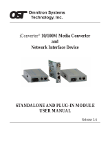
LinkFaultPassThrough(LFP)ApplicationNote
This media converter/switch has three ports, two TX and one FX. The LFP function
requires that in-band remote management be enabled. Next, it behaves differently,
depending on if VLAN is enabled or not. Therefore, LFP settings for this converter are
found under the VLAN sub-menu. When VLAN is enabled, a link loss on TX1 port (1)
will propagate to the remote TX1 port (2). Like wise, a link loss on TX2 will propagate
to the remote TX2 port. The fiber link will not be affected. If FX link is broken, all local
and remote TX ports will link down. If VLAN is disabled, any combination of loss of TX
port link will have no effect. In either VLAN enabled or disabled case, a FX link loss (3)
will forward to all TP ports (4), local and remote when LFP is enabled.
LEDIndicators
LED Function State Status
On Converter has power
Off Converter has no power or Port is disabled
PWR Power Indicator
Blinking While in rack, card is being upgraded
On LFP is enabled
LFP Link Fault Pass-through
Off LFP not enabled
On VLAN mode is enabled
VLAN 802.1Q VLAN mode
Off VLAN mode is not enabled
On Fiber link is OK
Off Fiber link is down
FX-LINK Fiber link & activity
Blinking Fiber link OK with activity
On UTP link is OK
Off UTP Link is down
TX-Link UTP Link (TX1 & TX2)
Blinking UTP link is OK with activity
On The connected UTP speed is 100M
TX-100 UTP Speed (TX1 & TX2)
Off No connection or the connected speed is 10M
PWR
LFP
VLAN
FX-LINK
LINK 100 LINK 100
TX2 TX1
TX1
FX
TX2
TX1
FX
TX2
(1) (2)
TX1
FX
TX2
TX1
FX
TX2
(3)
(4)
(4)
Installation
Connect Ethernet cables to the 10/100i-2E TP ports. Connect fiber cables to the FX
port. If the connected device also supports 802.3u auto-negotiation, the TP ports will
connect and LED indicators will show the speed connected. Follow the connection
examples below. Install the fiber converter/switch with the DC power adapter provided
(12VDC@1A) and then connect the adapter to an AC power outlet.
Connections
The following example illustrates the connection scheme when connecting from a
10/100BASE-TX port of one switch to a 100BASE-FX port of another switch through
the fiber converter.
The following VLAN example shows how a pair of the 10/100i(S)-2E can use their
tagged VLAN to create isolated Ethernet paths between the Sales group and their
server and between the R&D group and their server.
In this last example, because the 10/100i(S)-2E supports 802.1Q tagging, it can be
linked with other vendor's L2 managed switch to provide VLAN over fiber.
Managed L2 Switch
Supports VLAN Tagging
Dumb Switches
Group-A
Group-B
VID-A
VID-B100Base-FX Fiber
ConsoleTerminalOperation
To use this mode, the converter must be stand-alone and it must be inserted into a
stand-alone chassis with DB9 console port (such as CH01M).
Connect a Serial console Terminal with: 38.4K, 8bit, no parity, 1 stop, no handshaking
TP Setting Example
VLAN Setting Example
The VLAN settings can be used to separate traffic between each individual TP port.
The tagging can be done in point-to-point converters or when connected to a L2 switch
that supports 802.1Q VLAN tagging.
********************************************
*** CTC UNION TECHNOLOGIES CO.,LTD ***
*** FRM220 10/100I-2E Manager Ver:0.01 ***
********************************************
[Local ] [Ver:1.100-0.010-0.000-0.000] [ CH-01M ]
<1> Port Active: [ Enable ]
UTP1 Link: [UP ] Speed: [100 ] Duplex: [FULL]
UTP2 Link: [UP ] Speed: [100 ] Duplex: [FULL]
FX Link: [UP ] FEF:[ OFF ] Remote PWR: [ OK ]
<2> UTP1 Configurations
<3> UTP2 Configurations
<4> VLAN Configurations
<5> Auto Laser Shutdown: [OFF ]
<6> Remote Management: [Enable ]
<7> Remote Present: [ NO ]
<8> Send Remote Hardware Reset
<D> Small Form Pluggable:[ NO ]
<R> Port Reset
<S> Store Parameters
<F> Set Factory Default
Please select an item.
[Local ] [Ver:1.100-0.010-0.000-0.000] [ CH-01M ]
UTP1 Configuration
<1> Negotiation: [ Auto ]
<2> Speed Mode : [100 ]
<3> Duplex Mode: [FULL]
<4> Ingress Rate Limit: [No Limit][100.0M]
<5> Egress Rate Limit : [No Limit][100.0M]
<ESC> Go to previous menu. Please select an item.
--------------------------------------------------------------------
Negotiation Config
<0> Manual <1> Auto
Please select an item.
[Local ] [Ver:1.100-0.010-0.000-0.000] [ CH-01M ]
VLAN Configuration
<1> VLAN Mode: [ON ]
<2> UTP1 VID: [0010]
<3> UTP2 VID: [0020]
<4> Link Fault Pass-Through: [OFF ]
<ESC> Go to
p
revious menu. Please select an item.
MenuFunctionalDescriptions
<1> Port Active : When disabled, all transmissions through this card (except for OAM
management traffic) will be blocked
<2> UTP1 Configurations : The settings for auto negotiation or forced mode speed
and duplex, plus ingress/egress rate control are found under this sub-menu.
<3> UTP2 Configurations : Same setting here but for second TP port.
<4> VLAN Configurations : This sub-menu provides the VLAN settings, enable or
disable, plus the VID assigned to the TP port.
<5> Auto Laser Shutdown : This item toggles the ALS feature on or off.
<6> Remote Management : When disabled, no OAM traffic will be sent to the remote
unit. Use it to disable in-band management or to run the link at full 100%. When
remote management is enabled, some OAM packets use bandwidth for the in-band
management. They are very small percent but have highest priority.
<7> Remote Present : This item is an indicator only. If the fiber connects to a remote,
and it is detected by the local unit, it will report "YES" here.
<8> Send Remote Hardware Reset : This management feature allows the local
manager to force the remote unit to do a 'warm boot'.
<D> Small Form Pluggable : If the converter is the 10/100iS-2E model, it has an SFP
cage. This menu item will call a sub-menu to display the SFP information according to
the Multi-Source Agreement (MSA).
<R> Port Reset : This item will force the local unit to 'warm boot'. Confirmation is
required.
<S> Store Parameters : All settings made need to be save. This item performs the
save function. Confirmation is required.
<F> Set Factory Default : To bring the unit back to the factory default state, select this
menu item. Confirmation is required.
VLAN Configuration
<1> VLAN Mode : This toggle enables or disabled the VLAN feature.
<2> UTP1 VID : This item is used to set the VLAN Identifier for TP port 1. (1-4094)
<3> UTP2 VID : This item is used to set the VLAN Identifier for TP port 2. (1-4094)
<4> Link Fault Pass-Through : This item can enable or disable the LFP feature.
/