Page is loading ...

Owner’s Manual
CSW1012
Pure Sine Wave Inverter

i © 2013 Magnum Energy, Inc.
Disclaimer of Liability
Since the use of this manual and the conditions or methods of installation,
operation, use and maintenance of the CSW1012 inverter is beyond the
control of Magnum Energy, Inc., this company does not assume responsibility
and expressly disclaims liability for loss, damage or expense, whether direct,
indirect, consequential or incidental, arising out of or in any way connected
with such installation, operation, use, or maintenance.
Note as well that while every precaution has been taken to ensure the
accuracy of the contents of this manual, the specifi cations and product
functionality may change without notice. Magnum Energy, Inc. assumes no
responsibility for errors or omissions.
Restrictions on Use
The CSW1012 inverter may only be used in life-support devices or systems
with the express written approval of Magnum Energy. Failure of the CSW1012
inverter can reasonably be expected to cause the failure of that life-support
device or system, or to affect the safety or effectiveness of that device or
system. If the CSW1012 inverter fails, it is reasonable to assume that the
health of the user or other persons may be endangered.
Copyright Notice
Copyright © 2013 by Magnum Energy, Inc. All rights reserved. Permission to
copy, distribute, and/or modify this document is prohibited without express
written permission by Magnum Energy, Inc.
Document Information
Description – CSW1012 Owner’s Manual
Part Number and Revision – 64-0063 Rev A
Date Published – February 2013
This manual is printed without color for cost savings. However, this entire
manual is available for download under the Document Library tab at
www.magnumenergy.com with many of the fi gures available in color.
Contact Information
Magnum Energy, Inc. Phone: 425-353-8833
2211 West Casino Rd. Fax: 425-353-8390
Everett, WA 98204 Web:
http://www.magnumenergy.com
Statement of Appreciation
From all of us at Magnum Energy –
Thank you for purchasing this CSW1012 inverter.
We understand that you have many purchasing options in the marketplace,
and are pleased that you have decided on a Magnum Energy product.
At Magnum we are committed to providing you with quality products and
services, and hope that your experience with us is pleasant and professional.
Record the unit’s model and serial number in case you need to provide
this information in the future. It is much easier to record this informa-
tion now, instead of trying to gather it after the unit has been installed.
Model: Serial Number:
CSW1012
AU
Magnum Energy® is a registered trademark of Magnum Energy, Inc.

© 2013 Magnum Energy, Inc. ii
Important Product Safety Instructions
This manual contains safety instructions that must be followed during the
installation and operation of this product. Read all instructions and safety
information contained in this manual before installing or using this product.
Safety Symbols
To reduce the risk of electrical shock, fi re, or other safety hazard, the
following safety symbols have been placed throughout this manual to
indicate dangerous and important safety instructions.
WARNING: Indicates that failure to take a specifi ed action could
result in physical harm to the user.
CAUTION: Indicates that failure to take a specifi ed action could
result in damage to the equipment.
Info: Indicates information that emphasizes or supplements im-
portant points of the main text.
Product Safety Alerts
WARNINGS:
• All electrical work must be performed in accordance with local,
state and federal electric codes.
• This product is designed for indoor/compartment installation.
Do not expose to rain, snow, moisture, or liquids of any type.
• Use insulated tools to reduce the chance of electrical shock or
accidental short circuits.
• Remove all jewelry such as rings, watches, bracelets, etc., when
installing or performing maintenance on the inverter.
• Always disconnect the batteries or energy source prior to in-
stalling or performing maintenance on the inverter. Live power
may be present at more than one point since an inverter utilizes
both batteries and AC.
FCC Information
This equipment has been tested and found to comply with the limits for a
Class B digital device, pursuant to part 15 of the FCC rules. These limits are
designed to provide reasonable protection against harmful interference in
a residential installation. This equipment generates, uses, and can radiate
radio frequency energy and if not installed/used in accordance with the
instructions, may cause harmful interference to radio communications.
However, there is no guarantee that interference will not occur in a particular
installation. If this equipment does cause harmful interference to radio or
television reception—which can be determined by turning the equipment off
and on—the user is encouraged to try to correct the interference by one or
more of the following measures:
• Reorient or relocate the receiving antenna.
• Increase the separation between the equipment and the receiver.
• Connect the equipment to an outlet on a circuit different from that to
which the receiver is connected.
• Consult the dealer or an experienced radio/TV technician for help.

iii © 2013 Magnum Energy, Inc.
Tables
Table 2-1, DC Wire/Overcurrent Device for Rated Use ............................. 9
Table 2-2, Appliance Power Consumption and Run Time ........................ 11
Table 3-1, Examples of Digital Display Readings .................................. 15
Table 4-1, CSW1012 Inverter Error Codes ........................................... 17
Table 4-2, Troubleshooting Guide ....................................................... 17
Table 5-1, CSW1012 Specifications .................................................... 18
Table of Contents
1.0 Overview .................................................................................. 1
2.0 Installation .............................................................................. 3
2.1 Pre-Installation ........................................................................ 3
2.1.1 Installation Guidelines ........................................................ 3
2.1.2 Unpacking and Inspection ................................................... 3
2.1.3 Tools Required ................................................................... 3
2.2 Locating and Mounting the Inverter ............................................ 5
2.2.1 Locating the Inverter .......................................................... 5
2.2.2 Mounting the Inverter ......................................................... 6
2.2.3 CSW1012 Inverter Dimensions............................................. 7
2.3 Wiring the Inverter – General Requirements ................................ 8
2.3.1 Wiring Requirements .......................................................... 8
2.3.2 Torque Requirements .......................................................... 8
2.4 DC Wiring ............................................................................... 8
2.4.1 DC Wire Sizing................................................................... 9
2.4.2 DC Overcurrent Protection ................................................. 10
2.4.3 DC Grounding .................................................................. 10
2.4.4 DC Cable Connections ....................................................... 10
2.4.5 Wiring the Battery Bank .................................................... 11
2.4.6 Appliances and Run Time .................................................. 11
2.4.7 Wiring the Inverter to the Battery Bank............................... 12
2.5 Testing the Inverter ................................................................ 14
2.5.1 Inverter Functional Test .................................................... 14
2.5.2 GFCI Test ........................................................................ 14
3.0 Operation ............................................................................... 15
3.1 Understanding Loads .............................................................. 16
3.2 System Maintenance ............................................................... 16
4.0 Troubleshooting ..................................................................... 17
5.0 Specifi cations ......................................................................... 18
6.0 Limited Warranty ................................................................... 19
6.1 How to Receive Warranty Service ............................................. 19
List of Figures
Figure 1-1, Front Panel Features .......................................................... 1
Figure 1-2, Back Panel Features .......................................................... 2
Figure 2-1, Basic System Diagram ....................................................... 4
Figure 2-2, Approved Mounting Positions .............................................. 6
Figure 2-3, CSW1012 Dimensions ........................................................ 7
Figure 2-4, DC Cable to Battery Terminals ........................................... 13
Figure 2-5, DC Cable to Inverter’s DC Terminals .................................. 13

© 2013 Magnum Energy, Inc. 1
1.0 Introduction
1.0 Overview
Congratulations on your purchase of the CSW1012 pure sine wave inverter
provided by Magnum Energy, Inc. This inverter is designed to be powerful,
yet simple to operate, and will provide you with reliable AC power for trouble-
free use. Please read this chapter to familiarize yourself with the features
and benefi ts of your CSW1012 inverter.
45
6
1 2 3
7
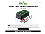
Figure 1-1, Front Panel Features
The front panel of the CSW1012 inverter is equipped with the following
features:
1. Status Indicator – an at-a-glance LED that provides the inverter’s sta-
tus—lights green, red, or amber (see Section 4.0 Operation).
2. Digital Display – a three-character alphanumeric display that shows
the inverter’s measured battery voltage, total AC output power, and any
error or warning codes.
3. Power/Select Button – a momentary button switch that allows the
inverter to be quickly turned on or off.
4. Remote Port – a RJ11 connector that allows an optional remote switch
to be connected via a remote cable. Note: Remote switch is sold sepa-
rately (PN:CSW-RS).
5. USB Port – allows USB-enabled devices to be powered and charged.
6. GFCI – a Ground Fault Circuit Interrupter protected AC outlet (with LED
indicator and test/reset capability). The GFCI outlet quickly stops the
fl ow of electricity in the event a ground fault occurs on the device that is
plugged into the inverter.
7. Serial Number – the unique identifi cation number assigned to each unit
(with a model-specifi c prefi x).

2 © 2013 Magnum Energy, Inc.
1.0 Introduction
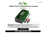
The back panel of the CSW1012 inverter is equipped with the following
features:
8. Cooling Fan – an intake cooling fan that automatically turns on when the
inverter’s internal temperature rises above 122 °F (50 °C). The fan turns
off when the inverter’s internal temperature falls below 122 °F (50 °C).
9. DC Negative Terminal (black) – the inverter’s connection to the nega-
tive terminal on the 12 VDC battery bank.
10. DC Positive Terminal (red) – the inverter’s connection to the positive
terminal on the 12 VDC battery bank.
11. Model Number – the model number of the inverter (i.e., CSW1012),
and regulatory compliance information.
12. DC Chassis Ground Screw – the connection that is used to tie the ex-
posed chassis of the inverter to the DC grounding system. The grounding
screw (8-32 x 3/8 Phillips PH) either connects to the vehicle’s chassis, to
the DC grounding bus, or to the engine’s negative bus.
13. Mounting Flanges (front and rear) – used to mount and secure the
inverter to a shelf/wall.
Figure 1-2, Back Panel Features
8 9 10
11
12
13
Regulatory Compliance
The CSW1012 inverter is intended to be used for land vehicles (RVs or
trucks) or marine craft. It has been tested and listed to UL 458, 5th Edition
(Power Converters/Inverters and Power Converter/Inverter Systems for
Land Vehicles and Marine Crafts) for use in the US; and is also certifi ed to
CSA C22.2 No. 107.1-01 (General Use Power Supplies) for use in Canada. It
has been tested and certified to these product safety standards by Intertek
Testing Services (known as ETL), which is a Nationally Recognized Testing
Laboratory (NRTL). NRTLs are qualified organizations that meet Occupational
Safety and Health Administration (OSHA) regulations to perform independent
safety testing and product certifi cation.

© 2013 Magnum Energy, Inc. 3
2.0 Installation
2.0 Installation
Review this section and the Important Product Safety Instructions before
proceeding with the installation of your inverter.
WARNING: Installations should be performed by qualifi ed per-
sonnel, such as a licensed or certifi ed electrician. The installer
determines which safety codes apply and ensures all applicable
installation requirements are followed. Applicable installation codes
vary depending on the specifi c location and application.
WARNING: Review the “Important Product Safety Information” on
page ii and adhere to all cautionary markings located on the inverter
and on the batteries.
2.1 Pre-Installation
Before proceeding, read the entire Installation section to determine how
best to install your CSW1012 inverter. The more thorough you plan in the
beginning, the better your inverter needs will be met. The simplifi ed system
diagram shown in Figure 2-1 should be reviewed to assist you in planning
and designing your installation. This drawing is not intended to override or
to restrict any national or local electrical codes. This drawing should not be
the determining factor as to whether the installation is compliant, that is the
responsibility of the electrician and the onsite inspector.
2.1.1 Installation Guidelines
• Before connecting any wires, determine the cable routes throughout the
home or vehicle/boat, both to and from the inverter.
• Always check for existing electrical, plumbing, or other areas of poten-
tial damage BEFORE drilling or cutting into walls.
• Make sure all wires have a smooth bend radius and do not become kinked.
• If installing this inverter in a boat, RV or truck, ensure the conductors
passing through walls, bulkheads, or other structural members are pro-
tected. This minimizes insulation damage (such as chafi ng) which can
be caused by vibration or constant rubbing.
2.1.2 Unpacking and Inspection
Carefully remove the inverter from its shipping container and inspect all
contents. Verify the following items are included:
• CSW1012 inverter
• CSW1012 Owner’s Manual
If items appear to be missing or damaged, contact your authorized Magnum
Energy dealer or Magnum Energy.
*** Save your proof-of-purchase as a record of your ownership; it is
needed if the unit should require in-warranty service. ***
2.1.3 Tools Required
Installing the inverter is simple and requires the following:
• Adjustable wrench (10mm) • Level • Drill
•
#10 Mounting screws (x4) • Pencil • Drill bits
• Phillips screwdriver

4 © 2013 Magnum Energy, Inc.
2.0 Installation
Figure 2-1, Basic System Diagram
AC
Main Panel
(Branch Circuit
Breaker:
15A max)
AC IN
AC OUT
AC Source
(120VAC, 60 Hz Sinewave)
CSW-TS15
Transfer Switch
CSW1012
Inverter
AC Loads
(15A max)
DVD
Tools
TV
AC
Sub-Panel
AC
Outlet
DC
Disconnect
Battery
Bank
Fuse
DC
Ground
(Vehicle chassis,
DC ground bus,
or engine
negative bus)

© 2013 Magnum Energy, Inc. 5
2.0 Installation
2.2 Locating and Mounting the Inverter
WARNINGS:
• Do not mount the inverter near any flammable or combustible
fluid or components.
• Provide adequate clearance/ventilation to the inverter. Do not
cover or obstruct any air vent openings and/or install in a zero-
clearance compartment.
2.2.1 Locating the Inverter
The inverter should only be installed in a location that meets the following
requirements:
Clean and Dry – The inverter should not be installed in an area that allows
dust, fumes, insects, or rodents to enter or block the inverter’s ventilation
openings. This area also must be free from any risk of condensation, water,
or any other liquid that can enter or fall on the inverter.
Inverter failure under
these conditions is not covered under warranty.
Cool – The inverter should be protected from direct exposure to the sun or
to any equipment that produces extreme heat. The ambient air tempera-
ture should be between 32° F (0° C) and 104° F (40° C); realize that the
inverter’s output specifications are rated at 77° F (25° C), so the cooler the
better within this range.
Ventilated – In order for the inverter to provide full output power and avoid
over-temperature fault conditions, do not cover or block the inverter’s ven-
tilation openings, or install this inverter in an area with limited airflow. Allow
as much clearance around the inverter’s intake cooling fan as possible. Al-
low a minimum airspace clearance of 3” (7.6 cm) around the unit to provide
optimum ventilation.
If installed in an enclosure, a fresh air intake opening must be provided
directly to the back side (cooling fan) and allow adequate space for the ex-
haust vents underneath the inverter. This will allow cool air from the outside
to flow into the inverter, and heated air to exit away from the inverter and
the enclosure. When mounted in an enclosed compartment, airflow must be
at least 59 cfm in order to maintain no more than a 68° F (20° C) rise in
compartment temperature.
Safe – Keep any flammable/combustible material (e.g., paper, cloth, plastic,
etc.,) that may be ignited by heat, sparks, or flames at a minimum distance
of 2 feet (60 cm) away from the inverter.
Do not install in any area that contains extremely flammable liquids like
gasoline or propane, or in locations that require ignition-protected devices.
Close to the battery bank – As with any inverter, it should be located as
close to the batteries as possible. Long DC wires tend to lose efficiency and
reduce the overall performance of an inverter. However, the unit should not
be installed in the same compartment as the batteries or mounted where it
will be exposed to gases produced by the batteries. These gases are corrosive
and will damage the inverter; also, if these gases are not ventilated and if
allowed to collect, they could ignite and cause an explosion.
Accessible – Do not block access to the front or back of the inverter. Allow
enough room to clearly view the digital display and to access the AC and DC
wiring connections—they will need to be checked and tightened periodically.
See Figure 2-3 for the CSW1012 inverter’s dimensions.

6 © 2013 Magnum Energy, Inc.
2.0 Installation
Figure 2-2, Approved Mounting Positions
For Indoor Use:
For RV Installation:
Mount flat on a
horizontal surface only
DO NOT mount with
DC terminals facing downward
2.2.2 Mounting the Inverter
Review the information in this section before mounting the inverter.
Orientating the Inverter
When mounted indoors, the CSW1012 inverter can be mounted on/underneath
a horizontal surface (shelf or table) or on a vertical surface (wall or bulkhead)
with the DC terminals facing left, right, or up—do not mount with the DC
terminals facing downward (see Figure 2-2). When mounted in an RV, mount
flat on a horizontal surface only.
Securing the Inverter
After determining your mounting position, use the base of the inverter’s
chassis as a template to mark your mounting screw locations (or, refer to the
dimensions in Figure 2-3). Remove the inverter and drill pilot holes into the
mounting surface. Secure the inverter to the surface using the appropriate
corrosion-resistant hardware (sized #10 – not supplied). If this unit is used
in a mobile application, you may want to place flexible washers or bushings
between the mounting surface and the inverter’s mounting flanges to reduce
vibration.

© 2013 Magnum Energy, Inc. 7
2.0 Installation
Figure 2-3, CSW1012 Dimensions
10 5/16"
(26.2 cm)
3 1/2"
(8.9 cm)
12 5/8"
(32.1 cm)
11 5/8"
(29.5 cm)
Front
(AC side)
Back
(DC side)
Top
7"
(17.8 cm)
6 1/2"
(16.5 cm)
2.2.3 CSW1012 Inverter Dimensions
Use the dimensions in Figure 2-3 to assist in mounting the CSW1012 inverter.

8 © 2013 Magnum Energy, Inc.
2.0 Installation
2.3 Wiring the Inverter – General Requirements
This section describes the requirements and recommendations for wiring the
CSW1012 inverter. Before wiring the inverter, carefully read all instructions.
WARNING: Wiring should meet all local codes/standards and be
performed by qualifi ed personnel (i.e., licensed electrician).
2.3.1 Wiring Requirements
• All conductors that are at risk for physical damage must be protected
by tape or placed in a raceway.
• Always check for existing electrical, plumbing, or other areas of
potential damage prior to making cuts in structural surfaces or walls.
• Where DC wiring must cross AC or vice-versa, try to make the wires at
the crossing point perpendicular (90 degrees) to one another.
• DC overcurrent protection must be provided as part of the installation.
• Use only copper wires with a minimum temperature rating of 75°C.
2.3.2 Torque Requirements
Torque all DC cable connections from 79 to 96 lbf-in (8.9 to 10.9 N-m).
2.4 DC Wiring
This section describes the inverter’s required DC wire sizes, the recommended
disconnect/overcurrent protection, and how to make the DC connections to
the inverter and the battery bank.
WARNING: Even though DC voltage is “low voltage”, signifi cant
hazards may be present, particularly from short circuits of the bat-
tery system.
CAUTION: The inverter is NOT reverse polarity protected—which
means that if the negative and positive battery voltage is connected
backwards to the inverter, the inverter will likely be damaged. You
should verify the correct voltage polarity using a voltmeter BEFORE
connecting the DC wires.
CAUTION: Before wiring the DC cables, review the safety informa-
tion at the beginning of this manual and the information below to
ensure a safe and long-lived system.
CAUTION: DO NOT connect the battery cables to the inverter until
all wiring is complete and the correct DC voltage and polarity have
been verifi ed.
Refer to Figure 2-4 when connecting the DC wires to the battery, and to
Figure 2-5 when connecting to the inverter. Also, consider the following
requirements to ensure maximum performance:
• The DC positive and negative cables connected to the inverter from the
battery bank should be tied together with wire ties/straps or electrical
tape approximately every 6 inches (15.3 cm). This helps improve the
surge capability and reduces the effects of inductance, which improves
the inverter waveform and reduces the wear of the inverter’s fi lter
capacitors. Keeping the battery cables close together also reduces the
chance of radio frequency interference.

© 2013 Magnum Energy, Inc. 9
2.0 Installation
• Crimped and sealed copper ring terminal lugs with at least a 6mm (1/4”)
bolt hole to connect the DC wires to the inverter’s DC terminals.
• The battery bank voltage MUST be between 10.5-15.5 for the inverter
to operate. If the voltage exceeds 16.0V, the inverter may be damaged.
• To ensure the maximum performance from the inverter, all connections
from the battery bank to the inverter should be minimized. The
exceptions are the DC fuse and disconnect or the DC circuit breaker—
required at the battery to protect the DC wiring—in the positive line. Any
other additional connection will contribute to additional voltage drops,
and these extra connection points may loosen during use.
• All wiring to the battery terminals should be checked periodically (once
a month) for proper tightness. The torque requirement for the DC
terminals is between 79 to 96 lbf-in (8.9 to 10.9 N-m). If you don’t have
a torque wrench, ensure all DC terminals are tight.
• Be aware that overtightening or misthreading the nuts on the DC
terminals can cause the bolts to strip and snap/break off.
• Make sure cables have a smooth bend radius and do not become kinked.
Follow existing wire runs where possible.
• A brief spark or arc may occur when connecting the battery cables to the
inverter DC terminals; this is normal and due to the inverter’s internal
capacitors being charged.
• Before routing the wiring, color code the DC cables/wires with colored
tape or heat shrink tubing: RED for positive (+); WHITE for negative (–);
and GREEN (or bare copper) for DC ground, to avoid polarity problems.
• Do not attempt to use the chassis in place of the battery negative
connection for grounding. The inverter requires a reliable return path
directly to the battery.
2.4.1 DC Wire Sizing
It is important to use the correct sized DC wire to achieve maximum effi ciency
from the system and to reduce fi re hazards associated with overheating.
Always keep your wire runs as short as practical to prevent low voltage
shutdowns and to keep the DC breaker from nuisance tripping (or open
fuses) because of increased current draw. The correct minimum DC wire
size (and corresponding overcurrent device) is required in order to reduce
stress on the inverter, minimize voltage drops, increase system effi ciency,
and ensure the inverter’s ability to surge heavy loads.
If the distance from the inverter to the battery bank is ≤5 feet, use a minimum
DC wire size of #2 AWG (33.6 mm
2
). If the distance between the inverter
and the battery is >5 feet, the DC wire will need to be increased. Longer
distances cause an increase in resistance, which affects the performance of
the inverter. From 5-10 feet, use a minimum wire size of #1/0 AWG (53.5
mm
2
) wire; from 10-15 feet, use a minimum wire size of #2/0 AWG (67.4
mm
2
) wire.
Table 2-1, DC Wire/Overcurrent Device for Rated Use
Inverter
Model
Minimum DC Wire
Size [rating]*
Maximum DC
Fuse Size
DC Grounding
Wire Size*
CSW1012
#2 AWG (33.6 mm
2
)
[170 amps]
150 amps
with time delay
#2 AWG
(33.6 mm
2
)
* Copper wire rated with 75°C (167°F) insulation at an ambient temperature
of 30°C (86°F) in free air.

10 © 2013 Magnum Energy, Inc.
2.0 Installation
2.4.2 DC Overcurrent Protection
For safety reasons and to comply with electrical code regulations, DC
overcurrent protection must be provided as part of the installation. The DC
overcurrent protection device must be installed in the positive DC cable line,
it can be a fuse (with a disconnect switch) or a circuit breaker and must
be DC-rated. It must be correctly sized according to the size of DC cables
being used, which means it is required to open before the cable reaches its
maximum current carrying capability, thereby preventing a fi re. The NEC
requires both overcurrent protection and a disconnect switch.
Because batteries can deliver thousands of amps in an instant during a
short, you are required to install a DC-rated fuse (or circuit breaker) that
has a interrupt current rating (known as Amps Interrupting Current or AIC)
that can withstand the short-circuit current without explosion or damage.
If a fuse is used as an overcurrent device, a Class-T type or equivalent is
highly recommended when used with inverters. A Class-T fuse is rated for
DC operation, can handle very high short-circuit currents (up to 100,000
amps), and has a time delay that allows for momentary current surges from
the inverter without opening the fuse. In some installations, if the combined
short-circuit current of all the batteries in the bank is determined to be
2,700 amps or less, then an ANL type of fuse may be used—if in doubt, use
a Class-T fuse. See Table 2-1 for the fuse size (coordinated with the DC wire
size) recommended for the CSW1012.
2.4.3 DC Grounding
The inverter should always be connected to a permanent, grounded wiring
system. The idea is to connect the metallic chassis of the various enclosures
together to have them at the same voltage potential, which reduces the
possibility for electric shock. For the majority of installations, the inverter
chassis and the negative battery conductor are connected to the system’s
ground bond via a safety grounding conductor (bare wire or green insulated
wire) at only one point in the system. Per the NEC, the DC grounding
conductor is required to be no less than the wire size of the DC positive/
negative cables. Use a ring terminal or box lug to connect the DC ground
wire to the DC ground screw (Figure 1-2, item 12). If the inverter is in a
vehicle, DO NOT connect the battery negative (-) cable to the vehicle’s frame/
safety ground—only connect to the inverter’s negative battery terminal.
See Table 2-1 for the ground wire size (coordinated with the DC wire size)
recommended for the CSW1012.
2.4.4 DC Cable Connections
Do not put anything between the battery cable ring lug and the battery post
(see Figure 2-4), or the fl at metal part of the inverter’s DC terminal (see
Figure 2-5). When connecting the battery cable, it should be placed directly
against the battery post or inverter terminal. Incorrectly installed hardware
causes a high resistance connection which could lead to poor inverter
performance, and may melt the cable and terminal connections.
Use an insulated 10mm wrench or socket to tighten the M6-1.0 Hex nuts to
79 to 96 lbf-in (8.9 to 10.9 N-m) for each inverter input terminal.
Info: The DC terminal and Hex nuts are made of stainless steel,
which have a high likelihood of galling or thread seizing while being
tightened. To reduce the risk of the bolt and nut seizing—causing
the bolts to strip or to snap/break off—use an anti-seize lubricant,
tighten the fasteners slowly (at low rpms) without interruption, and
apply only light pressure.

© 2013 Magnum Energy, Inc. 11
2.0 Installation
2.4.5 Wiring the Battery Bank
WARNING: Lethal currents will be present if the positive and
negative cables attached to the battery bank touch each other.
During the installation and wiring process, ensure the cable ends
are insulated or covered to prevent touching/shorting the cables.
Info: DO NOT connect the DC wires from the battery bank to
the inverter until 1) all DC wiring is complete, 2) the correct DC
overcurrent protection has been installed, and 3) the correct DC
voltage and polarity have been verifi ed.
Depending upon the voltage of the batteries (6 or 12 VDC), the batteries
must be wired in series, parallel, or series-parallel to provide the correct
voltage. The interconnecting DC wires must be sized and rated exactly the
same as those used between the battery bank and the inverter.
Place the batteries as close as practical to the inverter, preferably in an
insulated and ventilated enclosure. Allow adequate space above the batteries
to access the terminals and vent caps (as applicable). Also, allow at least 1”
of space between the batteries to provide good air fl ow. DO NOT mount the
batteries directly under the inverter.
CAUTION: Install batteries in a well ventilated area. Batteries can
produce explosive gasses. For compartment or enclosure installa-
tions, always vent batteries to the outside.
Info: To ensure the best performance from your inverter system,
batteries should be of the same size, type, rating, and age. Do not
use old or untested batteries.
2.4.6 Appliances and Run Time
The CSW1012 inverter can power a wide range of household appliances
including small motors, hair dryers, clocks, and other electrical devices.
As with any appliance using batteries for power, there is a certain length
of time that it can run—this is called “run time.” Table 2-2 below provides
estimates of power consumption and run time for various appliances using a
12V-120AH battery bank.
Table 2-2, Appliance Power Consumption and Run Time
Load Consumption Estimated Run Time
Cordless Phone 5W 180 hrs
Clock/Radio 8W 135 hrs
Table Lamp 40W/60W 27 hrs/18 hrs
Freezer (8.8 cu ft) 80W 15 hrs
20” LCD TV 100W 11.5 hrs
Refrigerator (18 cu ft) 120W 9 hrs
Sump Pump (1/2 hp) 350W 3 hrs
Microwave (mid-size) 1000W 49 min
Coffee Maker 1200W 37 min

12 © 2013 Magnum Energy, Inc.
2.0 Installation
3. Route and connect an appropriately sized DC positive wire (marked red)
from the inverter’s positive DC terminal (Item 10, Figure 1-2) to one
end of the fuse/disconnect assembly (or circuit breaker).
4. Connect a short wire (same rating as the DC wires) to the other side of
the DC circuit breaker (or one end of the fuse/disconnect assembly) and
the other end of the short wire to the positive terminal of the battery
bank (see Figure 2-1 for reference). This is essential to ensure even
discharging across the entire battery bank.
5. Ensure the DC wire connections (on the batteries, inverter, and DC circuit
breaker/fuse lugs) are fl ush on the surface of the DC terminals, and
the hardware (washer(s) and nut) used to hold these connections are
stacked correctly (see Figures 2-4 and 2-5). Verify all DC connections on
the inverter are torqued from 79 to 96 lbf-in (8.9 to 10.9 N-m).
6. Once the DC connections are completely wired and tested, coat the
terminals with an approved anti-oxidizing spray.
7. If the batteries are in an enclosure, perform a fi nal check of the
connections to the battery terminals, then close and secure the battery
enclosure.
8. Route an appropriately sized DC grounding wire (see Table 2-1 for
ground wire size) from the inverter’s DC chassis ground screw (Item 12,
Figure 1-2) to a dedicated system ground. It is recommended that you
connect the cable to the chassis ground screw with a copper, tin-plated
2.4.7 Wiring the Inverter to the Battery Bank
CAUTION: The inverter is NOT reverse polarity protected—if this
happens the inverter will be damaged and will not be covered
under warranty. Before connecting the DC wires from the batteries
to the inverter, verify the correct battery voltage and polarity using
a voltmeter. If the positive terminal of the battery is connected
to the negative terminal of the inverter and vice versa, severe
damage will result. If necessary, color code the cables (with
colored tape): red for positive (+), and white for negative (-) to
avoid polarity confusion.
Info: The DC overcurrent device (i.e., circuit breaker or fuse) must
be placed in the positive (red) DC cable line between the inverter’s
positive DC terminal and the battery’s positive terminal (red)—as
close to the battery as possible. For maximum protection, install it
within 18 inches (45 cm) of the battery.
Follow the steps below to wire the inverter to the battery bank:
1. Route an appropriately sized DC negative wire (marked white) from the
negative terminal of the battery bank to the inverter’s negative terminal
(Item 9, Figure 1-2).
2. Mount the fuse/disconnect assembly (or circuit breaker) as near as
practical to the batteries and leave open (i.e., no power to inverter).
WARNING: DO NOT close the DC circuit breaker or connect the
fuse to connect battery power to the inverter at this time. This will
occur after the installation is complete.
CAUTION: If connecting live battery cables to the inverter DC
terminals, a brief spark or arc may occur; this is normal and due
to the inverter’s internal capacitors being charged.

© 2013 Magnum Energy, Inc. 13
2.0 Installation
Figure 2-5, DC Cable to Inverter’s DC Terminals
DC cable
with ring lug
Inverter’s DC
+ terminal
M6-1.0 Hex nut
CAUTION:
Ensure nothing is placed
between the DC terminal
and the ring lug.
CSW1012
Inverter
Lock washer
#12 Flat washer
BATTERY
DC cable
with ring lug
bolt
flat washer
nut
lock washer
battery
post
battery terminal
Verify that the
DC cable lugs are flush
with the battery terminals.
Figure 2-4, DC Cable to Battery Terminals
ring terminal that accommodates a #8 screw, and is UL/CSA approved.
Recommended tightening torque is 20 lbf-in (2.3 N-m).
CAUTION: Ensure the total cable distance from the inverter to
the battery is within the requirement of Section 2.4.1 (DC Wire
Sizing).
9. Once the entire installation is complete, and all connections are verifi ed,
close the fuse disconnect (or circuit breaker) to provide power to the
inverter.

14 © 2013 Magnum Energy, Inc.
2.0 Installation
2.5.2 GFCI Test
Use the steps below to periodically test the GFCI to ensure it is functioning
properly.
1. Press the Power/Select button to turn on the inverter.
2. Plug a small AC load (e.g., 40W light bulb) into the GFCI’s outlet.
3. Check that the AC load is on (i.e., the bulb lights).
4. Press the GFCI’s TEST button. The GFCI’s RESET button should pop out,
and the power should shut off (light bulb goes out).
Note: If the bulb remains lit or the RESET button does not pop out, the
GFCI may not be functioning properly.
5. Press the RESET button. The AC load should come back on (bulb lights
again).
2.5 Testing the Inverter
Before proceeding, you must fi rst test whether the inverter was successfully
installed. Use the functional test below to test the inverter, and then perform
the GFCI test that follows to ensure the protection device is functioning
properly.
2.5.1 Inverter Functional Test
After all electrical connections to the inverter, batteries, and loads have
been completed, follow these steps to test the installation and the inverter’s
operation.
1. Press and hold the Power/Select button until a beep sound is heard
(about 1 second). The Status light turns on.
2. Check that the digital display alternately shows the inverter’s measured
battery voltage and output power.
3. Plug a small AC load (e.g., 40W light bulb or small appliance) into the
GFCI’s outlet.
4. Check that the AC load is on (i.e., the bulb lights).
Note: If the bulb does not light, the GFCI may have tripped. Reset the
GFCI by pressing the RESET button.
If the inverter passes all steps, it is functioning properly and ready for use.
If the inverter fails any of the steps, refer to the troubleshooting information
in Section 4.0.

© 2013 Magnum Energy, Inc. 15
3.0 Operation
3.0 Operation
The CSW1012 inverter uses a front panel that contains a power/select button,
a status indicator, a digital display for viewing system status, a remote port,
a USB port, and a GFCI AC output receptacle.
Power/Select Button
The Power/Select button is used to turn the inverter on and off. To turn the
unit on, press and hold the button for 1 second until you hear a “beep”. The
digital display alternately shows the unit’s measured battery voltage and AC
output power, and the status indicator lights green. Press the power/select
button to turn the unit off.
WARNING: The power/select button is not a power disconnect
switch and will not remove the DC power from the inverter.
Disconnect all power to the inverter before working on the inverter.
Status Indicator
The Status indicator on the front panel may light green, amber, or red to
indicate the inverter’s status. When the status indicator lights:
• Green – the inverter is operating normally.
• Amber – a warning has been detected. The inverter will shut down at
any time. Check the error code on the digital display.
• Red – an error has been detected and the unit has shut down. Check
the error code on the digital display.
When the status indicator lights amber or red, use the digital display and the
troubleshooting tables in Section 4.0 to resolve the issue.
Digital Display
The digital display has one line of three alphanumeric characters that
alternately shows the inverter’s measured battery voltage (in volts) and
AC output power (in kilowatts) under normal operating conditions. It also
displays error/warning codes that alert you to problems with the unit, and
are used in conjunction with the troubleshooting tables in Section 4.0 to
resolve any issues with the inverter’s operation. See Table 3-1 below.
Table 3-1, Examples of Digital Display Readings
Display Meaning
12.5 Measured battery voltage.
0.80 Total AC output power in kW (800W as shown).
E01 Error or warning code. See Troubleshooting section for details.
Remote Port
The Remote Port is used to connect an optional ON/OFF remote switch (sold
separately) that works in parallel with the power/select button.
USB Port
The USB Port enables you to power and charge a USB-enabled device
(provides 5 VDC/750 mA).
CAUTION: Some USB-powered products may be damaged when
connected to this USB port. If in doubt, check with the product’s
manufacturer.
GFCI Outlet
The two GFCI-protected AC outlets are used to plug in and power an AC load.
Protects the user against hazardous electrical shocks.

16 © 2013 Magnum Energy, Inc.
3.0 Operation
3.1 Understanding Loads
The inverter can power most loads within its power rating, however, there are
special conditions that can cause a load to behave differently than expected.
Following are some common problems encountered when using this inverter.
USB loads – When using the USB connector, be sure that the device you will
be connecting will accept 5 volts (≤ 750mA) and can be charged or powered
using another power source. The USB port can safely power and charge a lot
of devices such as: MP3 players, mobile phones, and portable video game
players. However, some devices such as GPS receivers and some cameras
may not work and may even be damaged. Refer to the owner’s guide for
each device to determine its compatibility.
Motor loads not starting – Some appliances, particularly those with
induction motors, require a much higher start-up surge than they do when
running. Pumps, freezers and refrigerators (compressors) are the most
common. The CSW1012 may not be able to start some of these appliances
even though their rated current draw is within the inverter’s limits. If a
motor-operated appliance refuses to start, observe the VOLTS indicator on
the digital display while you are trying to start the appliance. If the display
shows a battery drop below 11 volts while the inverter is trying to start the
motor, this may explain why the appliance won’t run. Make sure the length
and diameter of the battery cables are appropriate. Check that the battery
connections are good and that the battery is fully charged. If the cables are
sized correctly, the connections are good, and the battery is charged, you
may need a larger battery bank (see Loads turning on and off).
Loads turning off and on – If a load starts but quickly turns off, then the
battery may not be able to deliver the necessary amperage to drive the load.
If the battery bank cannot deliver the necessary amperage to drive a heavy
load, the inverter will shut OFF due to low voltage (<10.5 VDC). The battery
voltage can then slowly rise back above the low voltage reconnect voltage
(11.8 VDC) causing the inverter to resume operation. As soon as the heavy
load draws the batteries down, this cycle will continue unless the load is
reduced or more batteries are added.
Loads too large – Although the CSW1012 inverter can provide high surge
power up to two times the rated output power, some appliances may still
trigger the inverter shutdown/protection system. In these instances, a
higher power inverter may be required.
Running several loads at once – Sometimes the total surge requirement
of all the loads is higher than the CSW1012 inverter can deliver. You may
want to turn them on individually to ensure that the inverter does not have
to deliver the starting current for all the loads at once.
3.2 System Maintenance
Battery Charging
When possible, recharge your batteries when they are about 50% discharged
or earlier. This gives them a much longer life cycle than recharging when
they are almost completely discharged.
Inverter Maintenance
Routine maintenance is required to keep the CSW1012 inverter operating
properly. Periodically you should:
• Clean the exterior of the unit with a damp cloth to prevent the accumulation
of dust and dirt.
• Tighten the screws on the DC input terminals.
/