Page is loading ...

T E
C
H
N
0
L
0
G
I
E
S
11365 Surise Park Dr
-
Ranch0
Cordova
.
California 95742 USA
tel 916.351.1288
.
fax 916.351.0414
rev DC
-
6/22/99
SWINDSTRWM
G
I
E
S
LIL’WONDER
LIL’WONDER4
Power Amplifiers
OWNER’S MANUAL
AND
INSTALLATION GUIDE
IMMN.
SOUNDSTREAM.COM

Congratulations
Thanks for buying Soundstream’s Lil’ Wonder\Lil’ Wonder4.
We
have
always been known for amazing high-end power plants, and
to
show our
flexibility and versatility we make great equipment like this. Your new amp
has been designed to give you the “most performance available in
the
small-
est package possible.” Hence the name
Lil’ Wonder!
Pound for pound and
inch for inch these are some of the strongest amps ever made.
The
Lil’ Wonder\LiI’ Wonder4
are the ideal amps for almost any configura-
tion. They have the power to run front speakers, rear fill, a center channel, or
even more importantly, giant subwoofers. Don’t let their compact sizes fool
you, you’ll be amazed by the power. They have all of the technological
advantages of thier big
Rubicon
brothers, like a
RUBITM
power supply and
STACTTM
architecture. To get the most performance out of your system,
you’ll need to read this entire manual. It is the
only way to learn
about all of
the Lil’ Wonders’
capabilities and features. Please keep this manual and
your sales receipt
for future reference.
These gutsy amplifiers, like all Soundstream amplifiers, are the result of
American innovation and the highest quality control standards. When prop-
erly installed, it will provide you with many years of listening pleasure. Just
in case someone “borrows” your amplifier with no intention of returning it, fill
in the blanks below and stash them away in your permanent records. It will
help to protect your investment. Once you have done that, you’re ready to
rock. So hook it up, crank it up, and be amazed by your new
Lil’ Wonder\LiI’
Wonder4.
Model and Serial #
Dealer’s Name
Date of Purchase
Installation
Shop
Installation Date
CAUTION!
Prolonged listening at high levels may result in hearing loss.
Even though
your new Soundstream
Rubicon
ampfifier sounds better than anything
you’ve ever heard, exercise caution to prevent hearing damage.
2
Table of Contents
Design
Features . . . . . . . . . . . . . . . . . . . . . . . . . . . . . . . . . . . . . . . . . . . . .
,
.
.
.
.
.
.
.
.
.
.
.
.
.
.
.
p 4
-
5
Lil’ Wonder
Amplifier Diagram . . . . . . . . . . . . . . . . . . . . . . . . . . . . . . . . . . . . .
.
p 6
-
7
Lil’
Wonder4
Amplifier Diagram . . . . . . . . . . . . . . . . . . . . . . . . . . . . . . . . . . . . p 8
-
9
Crossover
&
Hawkins
Adjustments..
..............................
p 10
Hawkins Bass Contro
TM
Theory and Use
......................
p
II
lnstal
lnstal
lation:
Speaker Output Modes
...............................
p 12
lation:
Wiring and Diagram..
..................................
p 13
-
14
Installation: Mounting
.....................................................
p 15
Installation:
Level Setting and Front Spoiler.
.................. p 16
Protection Circuitry and Troubleshooting
....................... p 17
Service
...........................................................................
p 18
Specifications
.................................................................
p 18
Notes
..............................................................................
p 19

Design Features
RUBITM
Power
Supply
(Rapid-Use Branched Impulse) Our new
power supply eliminates “power sags” during low frequency re-
production by rapidly increasing the duty cycle, stabilizing the
power supply and allowing it to deliver the power required when
reproducing low frequencies. Also, greater reserve gate power
is now stored for low voltage conditions that occur during ex-
treme conditions.
STACTTM
(Stabilized Apex Current Topology) Reduces power
supply stress by 50%. Use of inverted channels usually de-
grades the stereo image due to phase reversal of even order
harmonic distortion that occurs between the inverted channels.
In the STACT design inversion is done at the power amplifier
drive stage. Since the fully symmetrical power amplifier pro-
duces no even harmonic distortion itself and all preamp circuitry
(which does produce even harmonics) is run completely in phase,
no even harmonic distortion phase reversal occurs.
CON
TridentTM
Protection Three types of protection for
RUBI~
amplifiers:
Output protection against short circuits or improper loads
Ground fault detection shuts down the amplifier when a signifi-
cant (5 volt or greater) voltage fluctuation occurs between audio
ground and battery ground.
Thermal protection will shut the amplifier down in extreme ther-
mal conditions.
Hawkins Bass Control Provides focused subwoofer boost and
routes wasted subsonic power to the audible bandwidth. The
Lil’
Wonders contain the fixed Hawkins Bass Control which al-
lows you to boost bass 6dB at 45Hz. A built-in subsonic filter at
45Hz helps protect the speakers.
Harmonic Bass Alignment
TM
The 2nd and 3rd order harmonic
peaks are critically aligned to fundamental peaks at low frequen-
cies. This produces tighter, more accurate bass reproduction.
4
Drive Delay II Muting
TM
Amplifier section now powers up 2
-
3
seconds after power supply, eliminating turn on pops. Turn off
process is reversed. Amplifier section turns off first, followed by
power supply.
Dynamically Optimized Power
GridTM
Power grid is now evenly
distributed between primary and secondary power supplies, pro-
viding greater dynamics and improved RF filtering.
ChassisinkTM
All transistors are sandwiched between the cir-
cuit board and the heatsink to provide cool efficient amplifier
operation in a smaller package.
,
Continuously Variable Lowpass Crossover Networks
(Lil’
Wonder4)
12dBIoct
Lowpass
crossover variable from 55 to
220Hz.
Built-in Staggered S.I.P. Crossover Networks Built-in
two-
way electronic crossover is designed to send either high or low
pass information to the amplifier with a
12dB/oct
slope (Highpass
only on the
Lil’
Wonder4).
Flexible Input Level Control 200mV to
5V
input sensitivity.
Stereo level control allows user to optimize system level control.
Symmetrical Discrete Balanced Class A Drive Boards Auto-
adjusts for linear performance in low impedance loads.
Removable Front Spoiler
Allows for stealth installation of RCA,
Speaker and Power wiring.
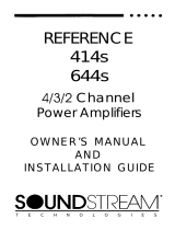
5

FUSE
BOITOM
VIEW
[FARTlAl)
1
.
2
.
3
m
4
.
5
.
6
.
7
.
8
.
9
.
10
.
11
.
12
.
Key
To
Cal/outs
Power LED
-
Indicates amplifier power.
Subsonic, Hawkins Bass Control, H.P. XOVER Switch
-
Selectable high pass filter frequency range. Select “SUB SONIC”
to engage the Sub Sonic filter at
13Hz
with no boost. Select
“Hawkins Bass Control” to engage the Sub Sonic filter at 45 Hz
with a
+6dB
boost. Select
“H.P.
XOVER” to engage the amplifier’s
high pass filter at 45Hz or
150Hz
(depending on
S.l.P.‘s)
for
running satellite speakers.
Low Pass XOVER Switch - Selectable low pass filter for driv-
ing subwoofers at
90Hz.
Note: Do not have the
“L.P.
XOVER”
and the
“HP
XOVER” engaged at the same time except for
bandpass operation.
MONO/ST Switch
-
Select “MONO” for bridged mono opera-
tion with a single input signal (right channel only). Select ‘ST”
for normal stereo operation.
FUSE
-
Main power supply fuse. Warning: Replace on/y with
the same
va/ue
fuse!
+12V - Connected to a fuse or circuit breaker, then to the
battery’s positive terminal.
REMOTE
-
Remote turn-on input from the head unit. Accepts
+12v.
GND - Main ground connection. Bolt to a clean chassis point in
the vehicle.
Speaker Connection Terminal
-
Speaker connections for
channels
l&2.
Input Levels
-
Stereo input level control.
RCA Inputs
-
Right and Left channel RCA inputs.
Crossover
S.I.P.‘s
-
Crossover frequency settings for ampli-
.
fier
.

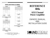
RUBICON
LIL’
WONDER4
-p-q-
..:...
.
..ii
i.....
.
.
..i_
.C..
,:,:_.
:;::
:...:.:
:.>
-------[~j----
---
Jf)P=W1FwmAL)
t-----------
1
\
0
0
I
BOTTOM VIEW
(PN?llAL)
8
9
1
.
2
.
3
.
4
.
5
.
6
.
7
.
8
.
9
.
10
.
11
.
12
.
13
.
14
.
15
.
16
.
17
.
Key
To
Cal/outs
Power LED
-
Indicates amplifier power.
Subsonic
/
Hawkins Bass Control Switch
-
Select ‘Subsonic”
to engage the Subsonic filter at
13Hz.
Select
“Hawkins
Bass
Control” to engage the
+6dB
boost
@
45 Hz for the
lowpass
channel.
ST/MO(R)/LP Switch - ‘ST” for normal stereo operation. “MO”
for bridged mono operation with a single input signal (right input
only). “LP” for low pass bridged mono operation with input from
channels
3&4.
ST/MO(
L)/LP
Switch
-
“ST” for normal stereo operation. “MO”
for bridged mono operation with a single input signal (left input
only). “LP” for low pass bridged mono operation with input from
channels
3&4.
Input Selection Switch
-
Selectable inputs from internal (chan-
nels
l&2)
or external (channels
3&4).
Fuse - Main power supply fuse. Warning: Replace on/y with
the same value fuse!
+12V
-
Connected to a fuse or circuit breaker, then to the
battery’s positive terminal.
Remote
-
Remote turn-on input from the head unit. Accepts
+12v.
GND
-
Main ground connection. Bolt to a clean chassis point in
the vehicle.
Speaker Connection Terminal
-
Speaker connections for
channels
l&2.
Speaker Connection Terminal
-
Speaker connections for
channels
3&4.
Low Pass Filter Control Adjustment
-
Crossover frequency
control for the internal low pass filter.
Input Levels
-
Stereo input level control for channels
l&2.
RCA Inputs
-
Right and Left channel RCA inputs for channels
l&2.
Input Levels
-
Stereo input level control for channels
3&4.
RCA Inputs
-
Right and Left channel RCA inputs for channels
3&4.
Crossover
S.l.P.‘s
-
Crossover frequency settings for ampli-
fier
.

Crossover
&
Hawkins Bass Control
Adjustments
CROSSOVER
In most car audio installations, there is a tendency for a
“midbass boom.” Because of their interior dimensions,
most cars will resonate or ring at these midbass frequen-
cies. If we design the system so there is reduced output
information in this region, the final response is very smooth
and natural sounding.
CHANGING FREQUENCIES
The Lil’ Wonder comes with a
9OHz
Low Pass S.I.P. and a 45Hz Hawkins and
High Pass S.I.P. (Series In-line Package resistor network) If you are using this
amplifier in the Low Pass Configuration, you will not need to change the S.I.P.
crossover. If you are using the amplifier in a High Pass configuration we
recomend
that you use a higher frequency
(150Hz)
for your crossover.
In
order to receive a
higher crossover point, remove the factory Low Pass
S.I.
P
(The S. 1.
P
with the
white
dot), and the factory High Pass/Hawkins
S.1.P
out of the amplifier. Place the
S./P
with the white dot in the socket for High Pass/Hawkins.
This will give
a
High
Pass frequency of
150Hz.
Then place the remaining S.I.P. in the Low Pass
socket. Make Sure That the Low Pass Crossover is NOT Engaged while the
High Pass crossover is engaged, unless a bandpass x-over is desired. If you
want to use a frequency other than the factory pre-set frequencies follow the chart
to the left or the formula below to select your own crossover points.
The Lil’ Wonder4 uses the same
S.I.P.‘s
for High Pass (factory set at 150 Hz) and
Hawkins as the Lil’ Wonder. However, the Low Pass is adjusted using a
lZdB/
act
variable crossover that has a range of 55 to 220 Hz. On either amplifer a full
range signal can be achieved by removing the S.l.P.3 entirely.
Hawkins Bass Control
-
Theory and We
Hawkins Bass Control (fixed) is a unique subwoofer control circuit included with
the Soundstream Lil’ Wonder\LiI’ Wonder4 amplifiers. It is capable of removing
subsonic energy in program material below 45 Hz at 12 dB/Octave, while boost-
ing subwoofer frequencies by
+6dB.
Once you engage the switch, you engage a
subsonic (High Pass) filter at 45 Hz, with a
+6dB
boost at 45 Hz.
I
Application
Subwoofer drivers in general have ex-
cellent power handling characteristics
5
over their operational bandwidth. This
0
bandwidth is determined by many fac-
tors, including driver design, and en-
closure type. It is possible to over-
-15
drive any subwoofer driver by send-
-20
ing
poyerful
signals outside of its op-
erational bandwidth. These poten-
Frequency
(Hz)
50
100
200
tially damaging signals can be re-
moved by adding a subsonic filter. Fig-
FIG. 1 Limited Excursion
ure 1 shows the effectiveness of the Hawkins Bass Control on woofer excursion
in a vented enclosure. The woofer travels 7.5 mm at 10 Hz. With Hawkins Bass
Control properly adjusted, this excursion can be reduced to less than 1 mm. This
is of great benefit to lowering woofer distortion and increasing output.
With Soundstream’s Hawkins Bass Control, the boost and frequency control
can provide the “tailoring” needed for any type of “assisted” design and any
woofer in any type of installation.
IO
11

f
INSTALLATION STEP 1
SELECTING THE SPEAKER OUTPUT MODE
The
RUBICON
Lil’
Wonder\Lil’
Wonder4 amplifiers have the ability to operate
in any one of the following modes:
Stereo (STACT
/
Mixed Mono): Use this mode for either stereo operation (left
and right channels) or for Mixed Mono operation (stereo left and right channels
plus bridged mono for a subwoofer).
.
Bridged Mono: Use this mode to get a bridged mono output while using only
the right channel input and gain control (for use with a singular mono input).
Please follow the wiring schemes below for the correct operation:
.
-
L +
-R+
I
BRIDGE
1
INSTALLATION STEP 2
)
POWER AND
GROUND
To ensure maximum output from your
RUBICON
Lil’
WondeALil’
Wonder4 am-
plifiers, use high quality, low-loss power and ground cables and connections.
The Lil’ Wonder\Lil’ Wonder4 amplifiers will accept up to 8 gauge power and
ground cables. Determine from the chart below the minimum gauge power and
ground wire for your application.
up
to
10'
up to 20’
I
Lil’
Wonder
I
8
or 10 gauge
I
8
gauge only
I
Lil’
Wonder4
8 or
10 gauge
8
gauge only
_
-
--__
,
’
’
‘\
\
CIRCUIT BREAKERS AND FUSES
/’
EXTERNAL
Like all audio components, the Lil’ Wonder\ Lil’ Wonder4 must be fused near the
battery. A fuse or circuit breaker must be located within 18” of the battery. This will
prevent a fire in the event of a shorted cable. See the chart below to determine the
correct fuse value.
INTERNAL
The Lil’
Wonder\LiI’
Wonder4 amplifiers are fused with automotive-type fuses.
In the event of a blown power supply fuse, replace with the correct value fuse
found in the chart below. Never replace the fuse with a higher value than what
m
+
_
+
\
is supplied. This may result in amplifier damage and will void the warranty!
.~
\
>\
/
MIXED MONO
-L+
-R+
RUB/CON Amplifier Fuse Values
Amplifier Fuse
Battery Fuse
/
Circuit
Breaker
1
Lil’
Wonder
1
25 amp automotive
1
30 amp
I
I
Lil’
Wonder4
I
(2) 20
amp automotive
I
40
amp
I
REMOTE TURN-ON
Connect the “Remote” line to the turn-on lead from the source unit. When
+I2
Volts is received, the amplifier will turn on.
13

WIRING cont’d
SIGNAL CABLE
Use a high quality cable that will be easy to install and has minimal signal loss to
guarantee optimum performance.
SPEAKER CABLE
The Lil’
Wonder\Lil’
Wonder4 amplifiers will accept up to 12 gauge speaker
cable. Use a high quality, flexible, multi-strand cable for best performance and
longevity.
SAMPLE WIRING DIAGRAM
FUSE
+ 12V REM GND
-Li
-R+
r-----
BRIDGE
.-I
r-
7
Ba!tery
krmtrxl
SPEAKERS
INSTALLATION STEP 3
)
INSTALLATION AND MOUNTING
AMPLIFIER LOCATlON
The Lil’ Wonder\LiI’ Wonder4 amplifiers employ highly efficient circuitry, a cus-
tom-engineered heat sink, and a unique Chassisink construction to maintain
lower operating temperatures. Additional cooling may be required if the amplifier
is located in a tightly confined area or when driving especially low impedance
loads at extremely high levels.
When mounting the amplifiers, they should be securely mounted to either a panel
in the vehicle or an amp board or rack that is securely mounted to the vehicle. The
mounting location should be either in the passenger compartment or in the trunk of
the vehicle, away from moisture, stray or moving objects, and major electrical com-
ponents. To provide adequate ventilation, mount the amplifier so that there are at
least two inches of freely circulating air above and to the sides of it.
MOUNTING THE AMPLIFIER
a.
Using the amplifier as a template, mark the holes on the mounting
surface.
b.
Remove the amplifier and drill the holes for the mounting screws.
C.
Secure the amplifier to the mounting surface using the supplied hardware.
WIRING
a.
Run and connect the audio signal and remote turn-on cables to the
amplifier from the source unit.
b.
Carefully run the positive cable from the amplifier to a fuse or circuit
breaker within
18”
of the battery.
C.
Connect the fuse or circuit breaker lead to the battery. Leave the circuit
breaker off or the fuse out until everything is bolted down.
d.
Secure the ground cable to a solid chassis ground on the vehicle. It may
be necessary to sand paint down to raw metal for a good connection.
e.
Double check each and every connection!
f.
Re-connect the fuse or circuit breaker.
POWER UP
Power up the system, there may be a 2-3 second delay from the time the source
unit is turned on to the time that the amplifier turns on, which is normal. Once the
amplifer LED is on and the source unit is playing, you should have sound coming
from the speakers.
14
15

INSTALLATION STEP 4
Trident Protection Circuitry
located on the front of the amplifier.
LEVEL SETTING
The input levels are adjusted by means of the stereo channel input level control
+
Your
Lil’
Wonder\Lil’
Wonder4 amplifier is protected against both overheating
A failsafe thermal protection circuit
and short circuits by means of main power supply fuses and the following
circuits:
+
Speaker output protection
+
Ground fault protection
In the ideal situation, all components in the audio system reach maximum undistorted
output at the same time. If you send a distorted signal to an amplifier, it is simply
going to amplify distorted information. The same holds true if an outboard proces-
sor or crossover begins to distort before you have maximum output from the ampli-
fier. By setting all components to reach clipping at the same time, you can maxi-
mize the output of your system. For the
RUBICON
amplifiers, follow these steps
for setting the input levels:
1.
Turn the amplifier’s input level to minimum position (counter-clockwise).
2.
Set the source unit volume to approximately
3/4
of full volume.
3.
While playing dynamic source material, slowly increase the amplifier’s input
level until a near maximum undistorted level is heard in the system.
FRONT SPOILER
Once the amplifier is installed and the proper levels set, place the front spoiler in
position, and bolt it on using the supplied hardware.
/NOTE: If you experience blown main power supply fuses, it is likely’
that the amplifier is seeing a dead short, either in the speaker wire or in
the speaker itself.
Rectify the problem before blowing multiple fuses!
DO NOT increase
values
beyond fhe original fuse value! Doing so will
void your warranty and may damage your amplifer.
Troubleshooting
PROBLEM
No Sound and power LED is not
.
Ilt
No sound, power LED is lit
Repeatedly blow amp fuse;
frequent activation of Trident
protection or Smart Power
Supply Circuit
Very little output, or output is
muffled
CAUSE
1. No power or ground at the
amp
2. No remote turn-on signal
3. Blown fuse near the battery
1. No signal input
2.
Speaker or leads may be
shorted
3. Speaker leads may be
referenced to ground
1. Speaker or leads may be
shorted
2. Amplifier load my be too low
3. Verify adequate amp
ventilation
Make sure that
both
the L.P. and
the H.P.
crossvers
arent
engaged
16
17

Service
Your Soundstream
RUBICON
amplifier is protected by a limited warranty.
Please read the enclosed warranty card for details and send it in.
Specifications
Power (4 ohm,
12.6~)
Power (2 ohm,
12.6~)
Power (2 ohm,
14.4~)
Power (4 ohms bridged,
14.4V)
Maximum rated power
Crossover
Damping
Frequency response
Color Factor
Hawkins Bass Control
Input sensitivity
Piercings
Shape bias
Signal to Noise
Stereo separation
THD
Dimensions
Lil’ Wonder:
Lil’ Wonder4:
Lots!
More!
Even more!
Huge!
NC-1 7
Up and Down
Wet, very wet
Flatter than a board
Blue
2 settings: Bass! And More Bass!
Don’t worry, you can’t offend it
Forty
100%
Foghorn to a dead monkey
Legally, but still see each other on Fridays
You can’t hear it
36” x 24” x 36”
(just kidding, 7” x 11
318”
x 2
l/4”)
44” x 24” x 24”
(just kidding, 11” x 11 318” x 2
l/4”)
Notes
18
19
/