Page is loading ...

InstallatIon GuIde
7360/7363 Thinline Series Icon Keypads
Description
The DMP Thinline™ Series Icon Keypads offer exible features and functionality in a stylish design. The 7300 Series
provides an easy to understand icon display to assist users when arming and disarming the system or using any of the
standard system features. The icons provide immediate
recognition of any system alarm as well as system status.
The Model 7360 provides three 2-button Panic keys, backlit
keyboard with easy-to-read lettering and an internal speaker.
The Thinline logo is also backlit.
Card Reader
The Model 7363 also provides a built-in proximity reader
designed to read standard HID proximity credentials. When a
proximity credential is presented to the internal reader, a beep
tone is heard to provide an audible acknowledgement of the
credential read.
Proximity Credentials Compatibility
DMP Keypads with internal proximity readers are compatible
with most standard 125Khz Prox credentials available from
HID and all DMP proximity credentials. DMP Keypads are not compatible with iClass or other non-HID credentials. There
are custom and non-standard credentials from HID that are not compatible with DMP proximity keypads. When using HID
cards that have not been purchased directly from DMP, thoroughly test the application fully before
installation. DMP does not guarantee compatibility with credentials not purchased from DMP.
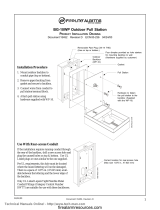
Installing the Keypad
All DMP keypad housings are designed to easily install on any 4” square box, 3-gang switch box,
DMP 695 and 696 backbox, or at surface. Figure 1 shows the keypad housing base mounting hole
locations.
Remove the Cover
The keypad housing is made up of two parts: the front, which contains the circuit board and keyboard
components and the base. Use the following steps to separate the keypad front and base.
1. Insert a at screwdriver into one of the slots on the bottom of the keypad and gently lift the
screwdriver handle toward you while pulling the halves apart. Repeat with the other slot.
2. Using your hands, gently separate the front from the base and set the front and components aside.
Harness Wiring
Figure 1 shows wiring harness assignments.
Observe wire colors when connecting the Red,
Yellow, Green and Black wires to the keypad
bus. When wiring directly to the panel terminals,
connect Red to panel terminal 7, Yellow to terminal
8, Green to 9 and Black to panel terminal 10. The
7360 and 7363 keypads are supplied with a 4-wire
harness for panel keypad bus connection. Since
all 7300 Series keypads operate together on the
Keypad bus using the same address, there is no
address option to set.
System Information Pull-Out Card
Included with the Icon keypad is a System
Information Pull-Out Card. User Code instructions
are on one side and the opposite side offers an
area to record zone numbers and names. Figure 1
shows the location of the pull-out card holder on
the back of the keypad. When inserting the System
Information Card while the keypad is attached to the
wall, rst insert the bottom of the card at an angle
to align the card into the bottom slot, then slide the card in place.
Lift screwdriver
handle up
toward you to
separate keypad
cover from base.
Thinline
Keypad
Building Wall
Thinline™ Series Icon Keypad
Icon Display
Shortcut and Digit keys
Backlit Logo
and Proximity
Antenna
COMMAND Key
Back Arrow Key
Select Keys
Surface and Backbox
Mounting Holes
Combined 4-square and 3-gang
switch box Mounting Holes
Keypad Back
Black – Ground
Green – Receive Data
Yellow – Send Data
Red – Keypad Power
Guide Tabs
Reference Card
Figure 1: Keypad Back with Wiring Harness

Digital Monitoring Products Thinline™ Series Icon LCD Installation Guide
2
Additional Power Supply
If the current draw for all keypads exceeds the panel output, provide additional current by adding a Model 505-12 auxiliary
power supply. Connect all keypad Black ground wires to the power supply negative terminal. Run a jumper wire from the
power supply negative terminal to the panel common ground terminal. Connect all keypad power (+12 VDC) wires to the
power supply positive terminal. DO NOT connect the power supply positive terminal to any panel terminal. Refer to the
505-12 Power Supply Installation Guide (LT-0453) for more information.
Panic Key Options
2-Button Panic Keys
All keypads offer a panic key function that allows users to send Panic, Emergency, or Fire reports to the central station.
In order to use the panic keys, enable the functions in the keypad user menu. See Programming Keypad Options later in
this document. Install the supplied icon labels below the top row of Select keys as shown in Figure 2.
Press and hold the two Select keys for two seconds until a beep from the
keypad is heard. At the beep, the panel sends the following zone alarm
reports to the central station. Note: All 7300 keypads send address 8 as a
default on panic alarms.
Panic (left two Select keys)—Zone 19
Emergency—non-medical (center two Select keys)—Zone 29
Fire (right two Select keys)—Zone 39
Internal Speaker Operation
All keypads emit standard tones for key presses, entry delay and system alerts. The speaker also provides distinct
burglary, re, zone monitor and prewarn cadences. The keypads provide an alternate prewarn with alarm cadence that
occurs when the status list displays a zone alarm.
Backlighting
On Thinline Icon keypads, both the logo and keyboard light when a key is pressed or the speaker sounds.
During an alarm condition, the keyboard and logo backlight turns Red. When all alarm conditions are cleared from the
display, the Red display turns off and the lighted areas return to the user-selected brightness.
End-User Options
All models provide three keypad adjustments the end-user can make through the User Options Menu.
Press and hold the Back Arrow (<—) and CMD (COMMAND) keys for two seconds to access User Options. Use the COMMAND
key to display the next option or press the Back Arrow to exit the User Options menu.
Backlighting Brightness (b 8)
Set the keypad LCD Display brightness level and the keyboard and logo backlighting by selecting
the desired brightness from the range of off (0) to maximum (8). The far left position displays b
(Brightness) and the far right position displays the selected brightness level. If the brightness level is
lowered, it reverts to maximum intensity whenever a key is pressed. If no keys are pressed and the
speaker has not sounded for 30 seconds, the user-selected brightness level restores. The default shown
is 8.
Internal Speaker Tone (S 5)
Set the keypad internal speaker tone from the range of 1-8. The far left position displays S (Speaker)
and the far right position displays the selected tone level. The default shown is 5.
Internal Volume Level (L 8)
Set the keypad internal speaker volume level for key presses and entry delay tone conditions from
the range of off (0) to maximum (8). The far left position displays L (Level) and the far right position
displays the selected volume level. During alarm and trouble conditions, the volume reverts to
maximum level. The default shown is 8.
Software Version (100)
The LCD displays the 3-digit software version of the keypad. Version 100 is shown in the example.
Keypad Model Number
The LCD displays the model number of the keypad.
(60) The Model 7360 keypad
(63) The Model 7363 keypad with built-in proximity reader
Top Row Select Keys
Police
Emergency
Fire
Label shows Icons only
Figure 2: Panic Key Label Placement

Thinline™ Series Icon LCD Installation Guide Digital Monitoring Products
3
Installer Options Menu
All models provide a Keypad Option and Diagnostic menu to allow installing and service technicians to congure and test
keypad operation. Since all 7300 Series keypads operate together on the Keypad bus using the same address, there is no
address option to set.
Accessing Installer Options
The Installer Options Menu can only be accessed from the User Options menu while displaying the Software Version or
Model Number. When either is displayed, enter the code 3577 (INST) and press COMMAND.
Programming Keypad Options
This menu allows the top row Select keys to be enabled as 2-button Panic keys and sets the number of digits for user codes
in the system.
Panic Keys (P 0)
Use this option to congure the top two left Select keys as 2-button Panic keys. The display
shows the current panic setting. The far left position displays P (Panic) and the far right
position displays the panic key setting. To enable the panic key operation press the number
one key. This toggles between one (1) and zero (0) on the display. Zero (0) disables this
option. The default shown is 0.
Emergency Key (E 0)
Use this option to congure the top two middle Select keys as 2-button Emergency keys. The
display shows the current emergency key setting. The far left position displays E (Emergency)
and the far right position displays the emergency key setting. To enable the emergency key
operation press the number one key. This toggles between one (1) and zero (0) on the display.
Zero (0) disables this option. The default shown is 0.
Fire Key (F 0)
Use this option to congure the top two right Select keys as 2-button Fire keys. The display
shows the current re key setting. The far left position displays F (Fire) and the far right
position displays the re key setting. To enable the re key operation press the number one
key. This toggles between one (1) and zero (0) on the display. Zero (0) disables this option.
The default shown is 0.
Number of User Code Digits (U 4) from Proximity Card Read (7363)
The 7363 keypad will convert proximity credential data into a four, ve or six digit code which
is then sent to the control panel. Enter the user code digit length used by the panel. The far
left digit displays U (User Code) and the far right position displays the user code digit length.
The default shown is 4 and is the proper setting for XT30, XT50, XRSuper6, XR20 and XR40
panels.
When searching the bit string from the reader for the user code, the digits are identied and
read from left to right. When a four-digit user code is selected only the rst four digits of the
string are read.
Keypad Diagnostics
LCD Segment Test
At diagnostics startup the keyboard is backlit at maximum brightness and all the icons ash on and then off as a group.
The keypad alternates between these two states for approximately two minutes. Press the Back Arrow to return to the
Panic Keys option. Press COMMAND at any time to continue to the next test.
Test Individual Keys and Card Read
When a top row select key is pressed, the corresponding Cancel, Bypass, Extend, or Verify option is displayed. When keys
0-9 are pressed, the number of the selected key is displayed in the 3-digit display. If a proximity credential is presented
during the key test, the keypad beeps once for a successful read.
Exiting the Installer Options
Press the Command key to end Installer Options. Press the Back Arrow key to return to the LCD Segments test.

LT-0953 1.01 © 2008 Digital Monitoring Products, Inc.
800-641-4282
www.dmp.com
Made in the USA
INTRUSION • FIRE • ACCESS • NETWORKS
2500 North Partnership Boulevard
Springfield, Missouri 65803-8877
8355
Wiring Specications for Keypad Bus
When planning a keypad bus installation, keep in mind the following specications:
1. DMP recommends using 18 or 22-gauge unshielded wire for all keypad and LX-Bus circuits. Do Not use
twisted pair or shielded wire for LX-Bus and keypad bus data circuits. To maintain auxiliary power integrity
when using 22-gauge wire do not exceed 500 feet. When using 18-gauge wire do not exceed 1,000 feet.
Install an additional power supply to increase the wire length or add devices.
2. Maximum distance for any one circuit (length of wire) is 2,500 feet regardless of the wire gauge. This
distance can be in the form of one long wire run or multiple branches with all wiring totaling no more than
2,500 feet. As wire distance from the panel increases, DC voltage on the wire decreases.
3. Maximum number of devices per 2,500 feet circuit is 40.
Note: Each panel allows a specic number of supervised keypads. However, 7300 Series keypads operate
together on a single address in an unsupervised mode.
4. Maximum voltage drop between the panel (or auxiliary power supply) and any device is 2.0 VDC. If the
voltage at any device is less than the required level, add an auxiliary power supply at the end of the circuit.
When voltage is too low, the devices cannot operate properly.
Refer to the LX-Bus/Keypad Bus Wiring Application Note (LT-2031) for more information. Also see the 710/710F Module
Installation Sheet (LT-0310).
FCC Information
This device complies with Part 15 of the FCC Rules. Operation is subject to the following two conditions:
(1) This device may not cause harmful interference, and
(2) this device must accept any interference received, including interference that may cause undesired operation.
Changes or modications made by the user and not expressly approved by the party responsible for compliance could void
the user’s authority to operate the equipment.
NOTE: This equipment has been tested and found to comply with the limits for a Class B digital device, pursuant
to part 15 of the FCC Rules. These limits are designed to provide reasonable protection against harmful
interference in a residential installation. This equipment generates, uses and can radiate radio frequency
energy and, if not installed and used in accordance with the instructions, may cause harmful interference
to radio communications. However, there is no guarantee that interference will not occur in a particular
installation. If this equipment does cause harmful interference to radio or television reception, which
can be determined by turning the equipment off and on, the user is encouraged to try to correct the
interference by one or more of the following measures:
- Reorient or relocate the receiving antenna.
- Increase the separation between the equipment and receiver.
- Connect the equipment into an outlet on a circuit different from that to which the receiver is connected.
- Consult the dealer or an experienced radio/TV technician for help.
Specications
Operating Voltage 12 VDC
Current Draw
7360 Normal Standby 60mA
Alarm 67mA
7363 Normal Standby 73mA
Alarm 80mA
Thinline Dimensions 7” W x 5.25” H x 0.5” D
Compatibility
XT30 and XT50 Series panels
XRSuper6, XR20 and XR40 Command Processor™
panels using Version 306 or higher.
Accessories
Proximity Credentials for use with Model 7363
1306P Prox Patch™
1306PW Prox Patch™ 26-Bit
1326 HID ProxCard II® Card
1346 HID ProxKey II® Access Device
1386 HID ISOProx II®
Backboxes
695 Keypad Conduit Backbox
696 Keypad Backbox
777 Protective Keypad Cover
Listings and Approvals
California State Fire Marshall (CSFM)
ETL: 3139201NYM
ANSI/SIA CP-01 False Alarm Reduction
ANSI/UL 1610 Central Station Burglar
ANSI/UL 609 Local Burglar
ANSI/UL 1076 Proprietary Burglar
ANSI/UL 365 Police Connected Burglar
ANSI/UL 1023 Household Burglar
ANSI/UL 985 Household Fire Warning
FCC Part 15 ID: CCKPC0086
Industry Canada ID: 5251A-PC0086
/