Hitachi SJ700 Series Software User manual
- Category
- Power adapters & inverters
- Type
- User manual
This manual is also suitable for

Powerful Inverter
with Sensorless Vector Control
series
S
J
700D
SJ700B
&
Hitachi Industrial Equipment Systems Co.,Ltd.
For More Precise Control For General Purpose Use

Dual rating
1
EzSQ improvement (1task/2ms 5 tasks/2ms)
2
RS485 Modbus-RTU communication speed is improved
(Max19.2kbps 115.2kbps speed is improved)
3
Approx. 6 times faster communication in comparison with the prior model is now supported.
Additionally, more communication commands are available.
By separating codes to be repeated as loops in different tasks, overall execution can be faster.
LCD operator
(Optional:WOP) upgrade
4
5-line LCD operator
Real time clock built in
4 sets of user parameter configurations
FDQEHVDYHGDQGWUDQVIHUUHGɑ
Two color backlight that
distinguish trip status
User selectable content for display.
Versatile functions
5
Phase loss input protection : covers not only the input but
output as well.
Automatic return to the initial display (b164):
Without operating for 10 minutes, the display returns to
the initial display automatically.
SJ700D can be used for both heavy and normal duty.
One-frame-size smaller SJ700D may be applicable for variable torque applications.
SJ700
SJ
SJ
SJSJ
J
S
S
J
70707070
70
7
7
7
7
7
7
7
0D0D0D
0D
0D
0D
D
D
D
D
0
D
0
-1-1
-1
1
-1
-1
1
5050
50
50
50
50
0
LFLFLFLF
LF
L
F3F3F3
F3
F
F
F
F
(1(1(1
(1
(
(
5k5k5k
5k
5
W)
W)
W)W)
W)
)
15kW
(overload capacity:150%,60sec)
18.5kW
(Overload capacity:120%,60sec)
Heavy duty: Conveyor, Lift Hoist, etc
Nomal duty: Fan, Pump, etc.
New
Line up
Pump
Hoist
Conveyor
(
Models: 3-ph,200V class 0.4 to 55kW,3-ph,400V class 0.75 to 132kW
)
FanFan
S
J
700D
series
1

Induction motor & permanent magnetic motor control
with one inverter
(PM motor control : ordering production)
Details of enhancement (Comparison between SJ700-2 and SJ700D-3)
6
The SJ700D series
inverter can drive both
induction motors (IM)and
permanent magnetic
motors (PM).
IM
PM
PM
+Dedicated Controller
IM+Inverter
The Hitachi SJ700D-3 series
succeed the SJ700-2 series with the additional
and enhanced features
No. item Enhanced function, added parameters, etc. Remarks
1 Model SJ700D-004 to 550LFF3/LFEF3/LFUF3 SJ700D-007 to 1320HFF3/HFEF3/1500HFUF3
2
Added
function
Constant torque/
Variable torque
(CT/VT) selection
Constant torque / Variable
torque mode selectable
(b049)
Newly added parameter b049 to switch between
Constant torque mode and Variable torque mode.
In case of driving light load application, you can
choose one power size smaller inverter or one
frame size smaller inverter.
3
PM motor control
[ordering production]
Control mode (A044) PM motor control (06) is added to the selection in A044
PM motor control is only available in Variable torque
mode.
(note) The model supporting PM motor control is
ordering production.
4
PM motor control
parameters (H101~H134)
Parameters related to PM motor control are newly added
(same as WJ200 series)
5
Automatic return
to the initial display
Automatic return
to the initial display (b164)
Without operating for 10 minutes,
the display returns to the initial display automatically.
6
Data read and
write
Data Read/Write selection
(b166)
Selection of enabling or disabling data Read / Write from the
copy unit WOP for parameter setting protection and security
7 Inverter mode
Inverter mode monitor
(d060)
Displays currently selected inverter mode, IM motor
(induction motor) or PM motor mode.(IM mode or PM mode.)
8
Phase loss
protection
Phase loss output
protection (b141,b142)
The inverter detects motor output phase loss
9
Improvement
function
EzSQ
Improvement
Parallel processing of 5 tasks
10
EzSQ starting trigger terminal: changed from FW terminal to
PRG terminal which can be assigned any of input terminals.
11
Additional function
Always running mode is added to
selection of starting method for EzSQ.
12
Command to store changed data into EEPROM (eepwrt command)
13 Command to obtain clock data from WOP (rtcset command)
14
Part of EzSQ program variables (P129 (U29) to P131 (U31))
are automatically stored at power down (only when A017 is
other than 00)
15
WOP operator
[Option]
Full compatibility with the copy unit WOP(5 line display)
16 Real time clock function is available.
17
RS485
Communication speed
is improved.
2400/4800/9600/19.2k/38.4k/57.6k/76.8k/115.2k bps
18
Modbus RTU
Maximum data length is expanded.
03h (Read holding register) 10h (Write in holding resisters)
4 registers (8 byte) to 16 registers (32 byte)
19
Command to write into/read from multiple holding registers
is added (17h: Write/Read multiple holding registers)
Read and Write 16 registers (32 byte)
20 Broadcast communication function is added.
21 EEPROM storing mode is added.
22
Initializing
Initializing method Parameter setting (b180=01) triggers initialization Initialization method of SJ700-2 is also valid.
23 Initializing of EzSQ Parameter b084 range is expanded.
24 Initial value b037=00 (Full access)
25
Selection of
initial display
Selection of initial display is expanded
(all monitoring parameters, frequency command F001 (WOP monitor B)
26
Others
Warnings Warnings are organized. 47 warnings to 31 warnings
27
Run command in
case of warnings
At occurrence of warning, the inverter does not accept Run command.
2

Possible with SJ700 series
Over-current suppress ON
Suppresses over current and continues running
Impact load
Motor current
Voltage of the
main circuit DC
Output frequency
High starting torque,
Powerful drive and easy setting
High starting torque
Trip avoidance function
Over current &
voltage suppress function
Improved sensorless vector control and auto tuning
produce high starting torque of 200% or more at 0.3Hz.*
1
Easy setup of motor constants
Ideal for applications which need high torque, such as
cranes, extruders and lifts.
Higher internal calculation speed improves current control
performance.
Over-current suppress and Over-voltage suppress functions
avoid inverter trips during acceleration and deceleration.
Hitachi exclusive
0Hz domain sensorless
vector control
Develops 150% (SJ700B:120%)
*
2
torque at
0Hz speed reference
Ideal for cranes and other applications
that require high torque upon starting.
*
2
when inverter is one frame size larger than motor.
Position control function
The SJ700D/SJ700/SJ700B, with optional feedback board
installed, together with an encoder-equipped motor can
perform position control.
For many applications, suitable performance can be
achieved at a lower cost than servo systems.
Based on your four motion parameters (position command,
speed command, acceleration time and deceleration time),
the SJ700D/SJ700/SJ700B will move an object from original
position A to target position B.
After the movement,
the inverter keeps
hold motor position.
DC bus AVR function
during deceleration
The SJ700D/SJ700/SJ700B controls deceleration time so that
the DC bus voltage does not exceed the over-voltage trip
level, providing trip-less operation during deceleration.
Motor Torque vs. Speed
Torque [%]
Speed (min
-1
)
200
100
0
-100
-200
300 600 900 1200 1500 1800
0.3Hz
Starting point A
Target point B
Over-current suppress OFF
Over-current trip
Frequency
Motor current
SJ700D(CT)
SJ700
Series Applicable motor
SJ700B
0.4 to 55kW
75 to 132kW
185 to 400kW
11 to 75kW
90 to 160kW
Starting torque
0.3Hz/200%
0.3Hz/180%
0.3Hz/150%
0.5Hz/150%
0.5Hz/120%
*1 Starting torque
*
)
*
)
*
) Derating is applied for SJ700B. Please consult technician at Hitachi or its distributor before use.
For More Precise Control For General Purpose Use
Series
Line up
S
J
700
S
J
700B
3

High performance, powerful functions,
yet user friendly.
Inverter control by built-in
programming functions
Custom operation is realized by downloading to an inverter a
user program created with ProDriveNext, Hitachi inverter
configuration software.
Tailor inverter operation to meet changing process
requirements, and replace separate PLCs in some cases.
By simplifying or eliminating external hardware, signficant cost
savings can be achieved.
Password function is incorporated to provide security for proprietary
program data against loss or unauthorized modification.
Built-in EMC filter up to 150kW
*
Cost and space reduction compared with external EMC filter.
Reduces electromagnetic noise.
Meets EN61800-3 2nd-Environment
*
SJ700: European Version and Japanese Version does not have 150 kW
SJ700B: All models 5.5kW is without EMC Filter
Built-in brake resistor
circuit up to 22kW
*
Cost and space reduction compared with external braking controller.
*
SJ700B: Up to 30kW
EMC Filter & brake circuit integrated as standard
Programming [EzSQ: easy sequence] function
Example (SJ700D-110HFEF3)
Frequency [Hz]
Level [db]
Typical example - Replacing external relay circuit
Item Description
Language SpecI/O functionReserved word
Language type BASIC Like
Supported Device
Windows (DOS/V)OS:WindowsVista, Windows7)
Programming
environment
Editor (Windows), Display (Windows)
Programmable flow control <Loop, Unconditional jump, conditional jump,
Time control, Sub routine, Others>
Operation command <+,-,,*, /, substitution, mod, abs>
I/O control (Bit input, Word input, Bit output, Word output)
Timer control <on delay, off delay>
Inverter parameter setting
User U (00)-U (31)/32 point
Timer UL (00)-UL (07)/8 point
Set frequency SET-Freq
Acceleration time
ACCEL
Deceleration time
DECEL
Monitor
Output frequency, Output current, Rotation direction,
PID feedback, Converted frequency, Output torque,
Output voltage, Power, Cumulative RUN time,
Cumulative power-on time, trip
General-purpose
input contact
X (00)-X (07)/8 point
General-purpose
output contact
Y (00)-Y (05)/6 point (1 point is relay output)
UB (00)-UB (07)/8 pointInternal user
TD (0)-TD (7)/8 point
Internal timer
contact
In a remote operator display code.
Inverter input
and output
Syntax check (Windows)
Program download/upload, All clear
Interpreter 2.0ms/command (Sub routine supported. 8 nested)
Memory area
Executable format
External input
External output
Command
Variable
1,024 steps or 6k byte
(Smaller of these)Program is stored in internal of inverter.
External digital
contact input
External analog
input
General-purpose
output terminal
Contact signal/Open collector signal input
(Internal DC24V power supply available)
Program RUN
command
SJ700D:PRG terminal
SJ700/SJ700B:FW terminal
General-purpose
input
Maximum of 8 point (X(00)-X (07))
XA (0) : 0-10V (O terminal)
XA (1) : 4-20mA (OI terminal)
XA (2) : 0-10V (O2 terminal)
External analog
output
YA (0) : Setup for FM terminal is possible.
YA (1) : Setup for AM terminal is possible.
YA (2) : Setup for AMI terminal is possible.
Maximum of 6 point (Y (00)-Y (05))
QP: Quasi Peak
*
Windows
®
is a registered trademark of Microsoft Corporation.U.S.A and other countries.
130
120
110
100
90
80
70
60
50
40
30
20
10
0
150k 200k 500k 1M 2M 5M 7M 10M 20M 30M
EN61800-3 2nd Environment
[C3]QP Limit Level
Standard Inverter SJ700 Using EzSQ
EzSQ
Programming
Download
Programming Window
4

Ease of maintenance Easy operation
Field replacement of cooling fan (s) and DC bus capacitors
can be accomplished in a fraction of the time.
Using Logic terminal move to SJ700D/SJ700 without wiring
change.
Read SJ300 Parameter by WOP remote operator and write
them in to SJ700D/SJ700
Displays only parameters changed from factory default
The Modbus-RTU communication is embedded as standard
along with a dedicated terminal.
Other fieldbus communications such DeviceNet and
PROFIBUS-DP are supported with optional fieldbus modules.
-DeviceNet is a trade mark of Open DeviceNet Vender Association, Inc.
-PROFIBUS-DP is a registered trade mark of PROFIBUS Nutzer
Organization
Long lifetime components &
Lifetime warning function
Long lifetime components
Design lifetime 10 Years or more for DC bus capacitors & Cooling
Fan.Cooling Fan ON/OFF control function for longer fan life.
*Condition for lifetime calculation -
Ambient temperature: 40 deg C (SJ700B: 30 deg C)
Ambient condition: No corrosive gas, oil mist nor dust
10 years is a design lifetime base on calculation, and not guaranteed
Lifetime warning function
Lifetime warning function helps to perform preventive
maintenance before a failure occurrence.
DC bus capacitor, cooling fan, heat sink temperature and
motor temperature can be monitored in order to replace
components prior to failure.
Easy-removable
DC bus Capacitors
(SJ700D/SJ700: above 15kW
SJ700B: above 18.5kW)
Easy-removable
Cooling Fan
SJ300series SJ700series
Network compatibility
Parameter
read write
Removable Control circuit terminals
(Move to SJ700D/SJ700 without rewiring)
Data comparison display mode
Direct digit edit mode for quicker selection of parameter.
Returning to output frequency monitor display (d001) by
holding the FUNC key for 3 seconds regardless of the
current content.
Other functions
Displays only pre-defined basic parameters which are used
commonly
Basic parameter display mode
Displays only user defined parameters
(up to 12 parameters, U001 to U012)
User-define parameter display mode
Basic
mode
Chose Basic
Parameter
Indication only
Basic Parameter
Easy-removable construction
for maintenance
User selection of displayed
parameters
Simple & Low cost wiring, ease of installation
and replacement using feildbus commuincation
*1 Control circuit terminals comparison table
Series Input terminals
SJ700D/SJ700
SJ700B
SJ300
L300P
Output terminals
5 terminals
(Open collector outputs)
2 terminals
(Relay outputs)
9 terminals
(Intelligent 8terminals,FW)
6 terminals
(Intelligent 5terminals,FW)
5

Conformity to global standards
CE, UL, c-UL, C-Tick approvals.
Micro surge voltage
suppress function
Wide Input power voltage range
Input voltage 240V for 200V class and 480V
for 400V class as standard.
Logic input & output terminal
apply sink & source logic
Environmental friendliness
Global standards
Motor terminal voltage
E=650V, cable=100m
EU RoHS compliant
EU RoHS compliant (except solder in power module)
Improvement of environmental tolerance
Varnish coating of internal PC board & plating of main circuit
copper bus bar are standard.
Versatile functions
Instantaneous power failure
disregard function
The SJ700D/SJ700/SJ700B overrides instantaneous power
failure when power fluctuation happens frequently, as long as
DC bus voltage remains higher than under-voltage trip level.
Emergency stop
Shuts down the inverter by hardware, bypassing
the CPU, to achieve a reliable, emergency stop function.
Intelligent input terminal and output
terminal ON/OFF delay function
Helps simplify external circuits.
Active frequency matching function
Motor frequency match restart function operates
effectively even without motor residual voltage.
Controlled deceleration and stop
on power loss
Analog input disconnection
detection function
The SJ700D/SJ700/SJ700B outputs a disconnection signal
when frequency command through analog input is lost.
Acceleration/Deceleration curve
functions
The curve shape (five types, such as S-curve, etc.) can be
chosen according to the application requirements.
Analog command holding
function (AHD)
Output frequency can be changed with UP/DOWN Function,
or with an analog signal as reference value. The set
frequency at power shutdown can be saved, too.
Pulse train input function
Pulse train input for Frequency reference or PID
feed back signal, with SJ-FB (speed feed back card option).
Integrated input electric power monitor
Input electric power (kW) and Integrated input electric
power for monitoring energy saving.
Automatic carrier frequency
adjustment function
The SJ700D/SJ700/SJ700B detects motor current and
automatically reduces carrier frequency according to the current.
The resolution of analog outputs
(voltage, current) is improved to 10 bits.
Hitachi original PWM control method limits motor terminal
voltage to less than two times of inverter DC bus voltage.
Lower than Hitachi motor Max. insulation voltage (1,250V)
(During regeneration, the motor terminal voltage may exceed the motor
maximum insulation voltage (1,250V))
1,250V
6

STANDARD SPECIFICATIONS
SJ700D /SJ700 Series
3-phase 200V class
Model SJ700D-
Enclosure (*1)
Applicable motor (4-pole, kW(HP)) (*2)
Output Ratings
Input Rating
Braking
Vibration (*5)
EMC filter
Zero-phase Reactor
Weight [kg] (lbs.)
IP20
Built-in (EN61800-3 category C3)
Built-in
CT:150%,60sec., 200%,3sec. VT:120%,60sec., 150%,5sec.
3-phase (3-wire) 200 to 240V (corresponding to input voltage)
3-phase 200 to 240V+10%, -15%, 50/60Hz±5%
Rated capacity
(kVA)
Rated output current (A)
Overload capacity(output current)
Rated output voltage (*3)
Rated input voltage (V)
Rated input current (A)
Dynamic braking (Short-time) (*4)
0LQLPXPYDOXHRIUHVLVWRUї
Rated capacity
(kVA)
Rated output current (A)
Overload capacity(output current)
Rated output voltage (*3)
Rated input voltage (V)
Rated input current (A)
Dynamic braking (Short-time) (*4)
0LQLPXPYDOXHRIUHVLVWRUї
US Version
JP Version
CT
VT
CT
VT
CT
VT
CT
VT
CT
VT
CT
VT
CT
VT
CT
VT
CT
VT
CT
VT
CT
VT
CT
VT
CT
VT
CT
VT
CT
VT
CT
VT
CT
VT
CT
VT
CT
VT
CT
VT
200V
240V
Built-in BRD circuit (optional resistor)
External dynamic braking unit (option)
-
2.9m/s
2
(0.3G), 10-55Hz
Model SJ700D-
Enclosure (*1)
Applicable motor (4-pole, kW(HP)) (*2)
Output Ratings
Input Rating
Braking
Vibration (*5)
EMC filter
Zero-phase Reactor
Weight [kg] (lbs.)
IP20
Built-in (EN61800-3 category C3)
Built-in
European Version
US Version
JP Version
400V
480V
Rated capacity
(kVA)
Rated output current (A)
Overload capacity(output current)
Rated output voltage (*3)
Rated input voltage (V)
Rated input current (A)
Dynamic braking (Short-time) (*4)
0LQLPXPYDOXHRIUHVLVWRUї
Model SJ700D-
Enclosure (*1)
Applicable motor (4-pole, kW(HP)) (*2)
Output Ratings
Input Rating
Braking
Vibration (*5)
EMC filter
Zero-phase Reactor
Weight [kg] (lbs.)
European Version
US Version
JP Version
400V
480V
Rated capacity
(kVA)
Rated output current (A)
Overload capacity(output current)
Rated output voltage (*3)
Rated input voltage (V)
Rated input current (A)
Dynamic braking (Short-time) (*4)
0LQLPXPYDOXHRIUHVLVWRUї
Model SJ700-
Enclosure (*1)
Applicable motor (4-pole, kW(HP)) (*2)
Output Ratings
Input Rating
Braking
Vibration (*5)
EMC filter
Zero-phase Reactor
Weight [kg] (lbs.)
European Version
US Version
JP Version
400V
480V
External dynamic braking unit (option)
-
2.9m/s
2
(0.3G), 10-55Hz
3-phase 400V class
CT:150%,60sec., 200%,3sec. VT:120%,60sec., 150%,5sec.
3-phase (3-wire) 380 to 480V (corresponding to input voltage)
3-phase 380 to 480V +10%, -15%, 50/60Hz±5%
550HFEF3
550HFUF3
550HFF3
55(75)
75(100)
76.2
93.5
91.4
112.2
112
135
123
149
30(66)
450HFEF3
450HFUF3
450HFF3
45(60)
55(75)
62.3
72.7
74.8
87.2
91
105
100
116
30(66)
370HFEF3
370HFUF3
370HFF3
37(50)
45(60)
51.9
58.8
62.3
70.6
75
85
83
94
30(66)
300HFEF3
300HFUF3
300HFF3
30(40)
37(50)
40.1
48.4
48.2
58.1
58
70
64
77
22(48.4)
4
000HFE2
4000HFU2
4000HF2
400(550)
-
554
-
665
-
800
-
840
-
360(792)
3150HFE2
3150HFU2
3150HF2
315(400)
-
416
-
499
-
600
-
630
-
210(462)
2200HFE2
2200HFU2
2200HF2
220(300)
-
305
-
366
-
440
-
455
-
145(319)
1850HFE2
1850HFU2
1850HF2
185(250)
-
256
-
308
-
370
-
389
-
140(308)
1320HFEF3
1500HFUF3
1320HFF3
132/150(175)
160(220)
180.1
200.9
216.1
241.1
260
290
286
300
70(154)
1100HFEF3
1100HFUF3
1100HFF3
110(150)
132(175)
150.3
159.3
180.4
191.2
217
230
239
253
70(154)
900HFEF3
900HFUF3
900HFF3
90(125)
110(150)
121.9
135
146.3
162.1
176
195
194
199
55(121)
750HFEF3
750HFUF3
750HFF3
75(100)
90(125)
103.2
110.8
123.8
133
149
160
164
176
55(121)
220HFEF3
220HFUF3
220HFF3
22(30)
30(30)
33.2
39.4
39.9
47.3
48
57
53
63
20
14(30.8)
185HFEF3
185HFUF3
185HFF3
18.5(25)
22(30)
26.3
29.7
31.5
35.7
38
43
42
47
24
14(30.8)
150HFEF3
150HFUF3
150HFF3
15(20)
18.5(25)
22.1
25.6
26.6
30.7
32
37
35
41
24
14(30.8)
110HFEF3
110HFUF3
110HFF3
11(15)
15(20)
17.3
20.0
20.7
24.1
25
29
30
32
35
6(13.2)
075HFEF3
075HFUF3
075HFF3
7.5(10)
11(15)
13.1
15.2
15.8
18.2
19
22
23
24
35
6(13.2)
055HFEF3
055HFUF3
055HFF3
5.5(7.5)
7.5(10)
9.7
11.0
11.6
13.3
14
16
17
20
70
6(13.2)
040HFEF3
040HFUF3
037HFF3
4.0(5)
5.5(7.5)
6.2
7.6
7.4
9.2
9.0
11.1
9.9
13.3
70
3.5(7.7)
022HFEF3
022HFUF3
022HFF3
2.2(3)
3.7(5)
3.6
4.6
4.3
5.5
5.3
6.7
5.8
8.1
100
3.5(7.7)
015HFEF3
015HFUF3
015HFF3
1.5(2)
2.2(3)
2.6
3.3
3.1
3.9
3.8
4.8
4.2
5.9
100
3.5(7.7)
007HFEF3
007HFUF3
007HFF3
0.75(1)
1.5(2)
1.7
2.1
2.0
2.5
2.5
3.1
2.8
4.3
100
3.5(7.7)
004LFUF3
004LFF3
0.4(1/2)
0.75(1)
1.0
1.2
1.2
1.5
3.0
3.7
3.3
3.9
50
3.5(7.7)
007LFUF3
007LFF3
0.75(1)
1.1(1.5)
1.7
2.1
2.0
2.6
5.0
6.3
5.5
7.2
50
3.5(7.7)
015LFUF3
015LFF3
1.5(2)
2.2(3)
2.5
3.2
3.1
3.9
7.5
9.4
8.3
10.8
35
3.5(7.7)
022LFUF3
022LFF3
2.2(3)
3.0(4)
3.6
4.1
4.3
4.9
10.5
12
12
13.9
35
3.5(7.7)
037LFUF3
037LFF3
3.7(5)
5.5(7.5)
5.7
6.7
6.8
8.1
16.5
19.6
18
23
35
3.5(7.7)
055LFUF3
055LFF3
5.5(7.5)
7.5(10)
8.3
10.3
9.9
12.4
24
30
26
37
16
6(13.2)
075LFUF3
075LFF3
7.5(10)
11(15)
11.0
15.2
13.3
18.2
32
44
35
48
10
6(13.2)
110LFUF3
110LFF3
11(15)
15(20)
15.9
20.0
19.1
24.1
46
58
51
64
10
6(13.2)
150LFUF3
150LFF3
15(20)
18.5(25)
22.1
25.2
26.6
30.3
64
73
70
80
7.5
14(30.8)
185LFUF3
185LFF3
18.5(25)
22(30)
26.3
29.4
31.5
35.3
76
85
84
94
7.5
14(30.8)
220LFUF3
220LFF3
22(30)
30(40)
32.9
39.1
39.4
46.9
95
113
105
120
5
14(30.8)
300LFUF3
300LFF3
30(40)
37(50)
41.9
48.4
50.2
58.1
121
140
133
150
22(48.4)
370LFUF3
370LFF3
37(50)
45(60)
50.2
58.5
60.2
70.2
145
169
160
186
30(66)
450LFUF3
450LFF3
45(60)
55(75)
63.0
72.7
75.6
87.2
182
210
200
240
30(66)
550LFUF3
550LFF3
55(75)
75(100)
76.2
93.5
91.4
112.2
220
270
242
280
43(94.6)
IP00
CT 150%,60sec., 200%,0.5sec. VT 120%,60sec., 150%,5sec.
3-phase (3-wire) 380 to 480V
(corresponding to input voltage)
3-phase 380 to 480V +10%, -15%,
50/60Hz±5%
External dynamic braking unit (option)
-
2.9m/s
2
(0.3G), 10-55Hz
Built-in (EN61800-3 category C3)
Built-in
IP00
CT 150%,60sec., 180%,0.5sec.
3-phase (3-wire) 380 to 480V
(corresponding to input voltage)
3-phase 380 to 480V +10%, -15%,
50/60Hz±5%
External dynamic braking unit (option)
-
1.96m/s2(0.2G), 10-55Hz
External Option
External Option
5.9m/s
2
(0.6G), 10-55Hz
Built-in BRD circuit (optional resistor)
5.9m/s
2
(0.6G), 10-55Hz
7

*1: The protection method conforms to JIS C 0920 (IEC60529)
*2: The applicable motor refers to Hitachi standard 3-phase motor (4-pole).To use other motors, be sure to prevent the rated motor current (50Hz) from exceeding the rated output current of the inverter.
*3: The output voltage decreases as the main power supply voltage decreases except for the use of AVR function.
*4: Braking resistor is not integrated in the inverter. Please install optional braking resistor or dynamic braking unit when large braking torque is required.
*5: Conforms to the test method specified in JIS C 60068-2-6 2010 IEC 60068-2-6 2007).
*6: To operate the motor beyond 50/60Hz, please consult with the motor manufacturer about the maximum allowable rotation speed.
*7: Storage temperature refers to the temperature in transportation.
*8: The frequency command is the maximum frequency at 9.8V for input voltage 0 to 10VDC, or at 19.8mA for input current 4 to 20mA.
If this characteristic is not satisfactory for your application,contact your Hitachi representative.
STANDARD SPECIFICATIONS
SJ700B Series
Series Name
Applicable Motor Capacity 004: 0.4kW (1/2HP)
|
4000:400kW (500HP)
Power Source
Available
0.4
(1/2)
Applicable Motor kW (HP)
0.75
(1)
1.5
(2)
2.2
(3)
3.7
(5)
4.0
(5)
5.5
(7.5)
7.5
(7.5)
11
(15)
15
(20)
18.5
(25)
22
(30)
30
(40)
37
(50)
45
(60)
55
(75)
75
(100)
90
(125)
110
(150)
132
(175)
150
(200)
160
(220)
185
(250)
220
(300)
315
(400)
400
(550)
SJ700D/SJ700 series
Model Name Indication
Model Configuration
3-phase 400V
3-phase 200V
L : 3-phase 200V class
H : 3-phase 400V class
F : With keypad
U : US version
E : European version
Note : Japanese version
F : Integrated EMC filter
Version
Series Name
Applicable Motor Capacity 055: 5.5kW (7.5HP)
|
1600:160kW (220HP)
Power Source
SJ700B series
L : 3-phase 200V class
H : 3-phase 400V class
F : With keypad
U : US version
Note : Asia version
F : Integrated EMC filter
3-phase 200V
3-phase 400V
SJ700D
SJ700B
3-phase 400V
*
1
*
1
SJ700
3-phase 400V
*1 Available only for Asia version and US Version. without EMC Filter
300HFF
300HFUF
30(40)
39.4
47.3
57
63
20
14(30.8)
370HFF
370HFUF
37(50)
48.4
58.1
70
77
22(48.4)
Built-in BRD circuit (optional resistor)
5.9m/s
2
(0.6G), 10-55Hz
3-phase 400V class
Model SJ700B-
Enclosure (*1)
Applicable motor (4-pole, kW(HP)) (*2)
Output Ratings
Input Rating
Braking
Vibration (*5)
EMC filter
Zero-phase Reactor
Weight (lbs.)
Asia Version
US Version
IP20 IP00
Rated capacity
(kVA)
Rated output current (A)
Overload capacity (output current)
Rated output voltage (*3)
Rated input voltage (V)
Rated input current (A)
Dynamic braking (Short-time) (*4)
0LQLPXPYDOXHRIUHVLVWRUї
400V
480V
External dynamic braking unit (option)
-
2.9m/s
2
(0.3G), 10-55Hz
110HFF
110HFUF
11(15)
15.2
18.2
22
24
35
6(13.2)
075HFF
075HFUF
7.5(10)
11
13.3
16
18
70
6(13.2)
055HF
055HFU
5.5(75)
9.7
11.6
14
17
70
-
-
3.5(7.7)
150HFF
150HFUF
15(20)
20.0
24.1
29
32
35
6(13.2)
185HFF
185HFUF
18.5(25)
25.6
30.7
37
41
24
14(30.8)
220HFF
220HFUF
22(30)
29.7
35.7
43
47
24
14(30.8)
450HFF
450HFUF
45(60)
58.8
70.6
85
94
30(66)
550HFF
550HFUF
55(75)
72.7
87.2
105
116
30(66)
750HFF
750HFUF
75(100)
93.5
112.2
135
149
30(66)
900HFF
900HFUF
90(125)
110.8
133
160
176
55(121)
1100HFF
1100HFUF
110(150)
135.1
162.1
195
199
55(121)
1320HFF
1320HFUF
132(150)
159.3
191.2
230
253
70(154)
1600HFF
1600HFUF
160(220)
200.9
241.1
290
300
70(154)
Built-in BRD circuit (optional resistor)
3-phase 200V class
Model SJ700B-
Enclosure (*1)
Applicable motor (4-pole, kW (HP)) (*2)
Output Ratings
Input Rating
Braking
Vibration (*5)
EMC filter
Zero-phase Reactor
Weight (lbs.)
US Version
IP20
120%,60sec
3-phase (3-wire) 200 to 240V (corresponding to input voltage)
3-phase 200 to 240V +10%, -15%, 50/60Hz±5%
Built-in (EN61800-3 category C3)
Built-in
200V
240V
Rated capacity
(kVA)
Rated output current (A)
Overload capacity (output current)
Rated output voltage (*3)
Rated input voltage (V)
Rated input current (A)
Dynamic braking (Short-time) (*4)
0LQLPXPYDOXHRIUHVLVWRUї
External dynamic braking unit (option)
-
2.9m/s
2
(0.3G), 10-55Hz
110LFUF
11(15)
15.2
18.2
44
48
10
6(13.2)
150LFUF
15(20)
20.0
24.1
58
64
10
6(13.2)
185LFUF
18.5(25)
25.2
30.3
73
80
7.5
14(30.8)
220LFUF
22(30)
29.4
35.3
85
94
7.5
14(30.8)
300LFUF
30(40)
39.1
46.9
113
120
7.5
14(30.8)
370LFUF
37(50)
48.4
58.1
140
150
22(48.4)
450LFUF
45(60)
58.5
70.2
169
186
30(66)
550LFUF
55(75)
72.7
87.2
210
240
30(66)
750LFUF
75(100)
93.5
112.2
270
280
43(94.6)
5.9m/s
2
(0.6G), 10-55Hz
120%,60sec
3-phase (3-wire) 380 to 480V (corresponding to input voltage)
3-phase 380 to 480V +10%, -15%, 50/60Hz±5%
Built-in (EN61800-3 category C3)
Built-in
HFUF
LFUF
LFUF3
HFEF3
HFUF3
HFF3
LFF3
HFF
HF2
HFE2
HFU2
8

SPECIFICATIONS
General Specifications
Items
Control
Input signal
Output signal
Monitoring on display
Other functions
Frequency
setting
Operator
External signal(*8)
External port
Operator
Forward /reverse
Start /stop
External signal
External port
Setting via RS485 communication
Terminals
Intelligent
input terminals
8 terminals, NO/NC switchable, sink logic/source logic switchable
Functions
1 terminal (PTC characteristics)Thermistor input
Control method
Output frequency range (*6)
Frequency accuracy
Frequency resolution
Line to line sine wave pulse-width modulation (PWM) control
0.1-400.0Hz(400kW:0.1-120Hz)
'LJLWDORIWKHPD[LPXPIUHTXHQF\$QDORJÝ&
Digital setting: 0.01Hz, Analog setting: (Maximum frequency)/4,000 (O terminal: 12bit 0-10V, O2 terminal: 12bit -10-+10V)
±0.5% (sensorless vector control)
0.01-3,600sec. (Linear/curve, accel./decel. selection), Two-stage accel./decel.
SJ700/SJ700D (CT) 0.5 to 15kHz, (VT) 0.5 to 12 kHz, 75kW to 150kW (CT) 0.5 to 10kHz, (VT) 0.5 to 8 kHz,185kW and over : 0.5 to 3.0kHz
SJ700B : 0.5 to 12.0kHz (90kW and over : 0.5 to 8.0kHz)
Performs at start: under set frequency at deceleration, via an external input (braking force, time, and operating frequency).
Up and Down keys
'&99LQSXWLPSHGDQFHNїP$LQSXWLPSHGDQFHї
Setting via RS485 communication
Start/stop commands (forward/reverse switching by parameter setting)
General Specifications
Forward-operation start/stop commands (reverse-operation start/stop possible when relevant commands are assigned to intelligent input terminals)3-wire
input possible (when relevant commands are assigned to control circuit terminals)
Reverse operation (RV), Multi-speed 1 setting (CF1), Multi-speed 2 setting (CF2), Multi-speed 3 setting (CF3), Multi-speed 4 setting (CF4), Jogging (JG),
external DC braking (DB), 2nd motor control (SET), 2-stage acceleration/deceleration (2CH), free-run stop (FRS), external trip (EXT), unattended start
protection (USP), commercial power supply switching (CS), software lock (SFT), analog input switching (AT), 3rd motor control (SET3), reset (RS), starting by
3-wire input (STA), stopping by 3-wire input (STP), forward/reverse switching by 3-wire input (F/R), PID disable (PID), PID integration reset (PIDC), control
gain switching (CAS), acceleration by remote control (UP), deceleration by remote control (DWN), data clearance by remote control (UDC), forcible operation
(OPE), Multi-speed bit 1 (SF1), Multi-speed bit 2 (SF2), Multi-speed bit 3 (SF3), Multi-speed bit 4 (SF4), Multi-speed bit 5 (SF5), Multi-speed bit 6 (SF6),
Multi-speed bit 7 (SF7), overload restriction selection (OLR), torque limit selection (enabling/disabling) (TL), torque limit 1 (TRQ1), torque limit 2 (TRQ2), P/PI
VZLWFKLQJ33,EUDNLQJFRQILUPDWLRQ%2.RULHQWDWLRQ257/$'FDQFHOODWLRQ/$&FOHDUDQFHRISRVLWLRQGHYLDWLRQ3&/5SHUPLVVLRQRIÝVKLIWSKDVH
(STAT), trigger for frequency addition (A145) (ADD), forcible-terminal operation (F-TM), permission of torque command input (ATR), cumulative power
clearance (KHC), servo-on (SON), pre-excitation (FOC), general-purpose input 1 (MI1), general-purpose input 2 (MI2), general-purpose input 3 (MI3),
general-purpose input 4 (MI4), general-purpose input 5 (MI5), general-purpose input 6 (MI6), general-purpose input 7 (MI7), general-purpose input 8 (MI8),
analog command holding (AHD), Multistage position settings selection 1 (CP1), Multistage position settings selection 2 (CP2), Multistage position settings
selection 3 (CP3), Zero-return limit function (ORL), Zero-return trigger function (ORG), Forward drive stop (FOT), reverse drive stop (ROT), Speed / position
switching (SPD), Pulse counter (PCNT), Pulse counter clear (PCC), Emergency stop (EMR) ,EzSQ PRG-Run(PRG)(*12) ,no assignment (no)
Running (RUN), constant-speed reached (FA1), set frequency overreached (FA2), overload notice advance signal (1) (OL), output deviation for PID control
(OD), alarm signal (AL), set frequency reached (FA3), over-torque (OTQ), instantaneous power failure (IP), undervoltage (UV), torque limited (TRQ),
operation time over (RNT), plug-in time over (ONT), thermal alarm signal (THM), brake release (BRK), braking error (BER), 0Hz detection signal (ZS),
speed deviation maximum (DSE), positioning completed (POK), set frequency overreached 2 (FA4), set frequency reached 2 (FA5), overload notice
advance signal (2) (OL2), PID feedback comparison (FBV), communication line disconnection (NDc), logical operation result 1 (LOG1), logical operation
result 2 (LOG2), logical operation result 3 (LOG3), logical operation result 4 (LOG4), logical operation result 5 (LOG5), logical operation result 6 (LOG6),
capacitor life warning (WAC)(*11), cooling-fan speed drop (WAF), starting contact signal (FR), heat sink overheat warning (OHF), low-current indication
signal (LOC), general-purpose output 1 (M01), general-purpose output 2 (M02), general-purpose output 3 (M03), general-purpose output 4 (M04),
general-purpose output 5 (M05), general-purpose output 6 (M06), inverter ready (IRDY), forward rotation (FWR), reverse rotation (RVR), major failure
(MJA), window comparator O (WCO), window comparator OI (WCOI), window comparator O2 (WCO2), alarm code 0 to 3 (AC0 to AC3)
Free V/f setting (7 breakpoints), frequency upper/lower limit, jump (center) frequency, acceleration/deceleration according to characteristic curve, manual
torque boost level/breakpoint, energy-saving operation, analog meter adjustment, start frequency setting, carrier frequency adjustment, electronic thermal
function (available also for free setting), external start/end frequency/frequency rate, analog input selection, retry after trip, restart after instantaneous power
failure, output of various signals, starting with reduced voltage, overload restriction, initial-value setting, automatic deceleration at power failure, AVR function,
fuzzy acceleration/deceleration, online/offline auto-tuning, high-torque multi-motor operation (*11) (sensorless vector control of two motors by one inverter)
SJ700D IM : V/f optionally variable (30-400Hz of base frequency), V/f control (constant torque, reduced torque), sensorless vector control,0Hz ranged
sensorless vector control (only CT), vector with sensor (SJ-FB card option , only CT) [ordering production] PM : sensorless vector control (only VT)
SJ700/SJ700B IM : V/f optionally variable (30-400Hz of base frequency), V/f control (constant torque, reduced torque), sensorless vector control
0Hz ranged sensorless vector control, vector with sensor (SJ-FB card option)
Protective functions
Environmental
conditions
Options
*1 : The protection method conforms to JIS C 0920 (IEC60529)
*2 : The applicable motor refers to Hitachi standard 3-phase motor (4-pole). To use other motors, be sure to prevent the rated motor current (50Hz) from exceeding the rated output current of the inverter.
*3 : The output voltage decreases as the main power supply voltage decreases except for the use of AVR function.
*4 : Braking resistor is not integrated in the inverter. Please install optional braking resistor or dynamic braking unit when large braking torque is required.
*5 : Conforms to the test method specified in JIS C 60068-2-6:2010 (IEC 60068-2-6:2007).
*6 : To operate the motor beyond 50/60Hz, please consult with the motor manufacturer about the maximum allowable rotation speed.
*7 : Storage temperature refers to the temperature in transportation.
*8 :
The frequency command is the maximum frequency at 9.8V for input voltage 0 to 10VDC,or at 19.8mA for input current 4 to 20mA.If this characteristic is not satisfactory for your application,contact your Hitachi representative.
6-%VHULHVLVWRʝ6-'97WRʝ
*10 : Please be sure to connect DC reactor attached to 1850HF,2200HF,3150HF and 4000HF. (1850HF,2200HF and 3150HF of US/JP Version:The DC reactor is not attached.)
*11 : 1850HF,2200HF,3150HF and 4000HF:The function is not provided.
*12 : SJ700D-3 only.
*13 : The option cannot access new parameters in SJ700D-3.
Ambient operating/storage
temperature (*7)/ humidity
Overcurrent protection, overvoltage protection, undervoltage protection, electronic thermal protection, temperature error protection, instantaneous power
failure protection, phase loss input protection, braking-resistor overload protection, ground-fault current detection at power-on, USP error, external trip,
emergency stop trip, CT error, communication error, option board error, and others
Terminals
Intelligent
output terminals
Functions
Analog voltage output, analog current output, pulse-string output (e.g., A-F, D-F [n-fold, pulse output only], A, T, V, P)
Ý& (*9)Ý&5+1RFRQGHQVDWLRQ
Location Altitude 1,000m or less, indoors (no corrosive gases or dust)
SJ-DG (4digits BCD, 16bits binary)
SJ-FB (vector control loop speed sensor)
SJ-DN2 (DeviceNet (TM)) (*13), SJ-PB (T)2 (PROFIBUS) (*13)
EMI filters, input/output reactors, radio noize filters, braking resistors, braking units, LCR filter, communication cables
Digital input expansion card
Feedback expansion card
Network interface card
Others
Output frequency, output current, output torque, frequency conversion data, trip history, input/output terminal status, electric power, and others
Monitor output
terminals
5 open-collector output terminals, NO/NC switchable, sink logic/source logic switchable 1 relay (1c-contact) output terminal: NO/NC switchable
SJ700/SJ700D (CT) (0Hz domain with motor one frame size down) 150% at around 0Hz, 75kW and over: 130% at around 0Hz.
SJ700B : 120% at around 0Hz,SJ700D (VT):Disable.
SJ700D (0.4 to 132kW) : 50% (at 10% of motor constant speed) [ordering production] (only SJ700D (VT))
SJ700/SJ700D (CT) 200%/0.3Hz, (VT) 150%/0.5Hz, 75kW to 150kW (CT) 180%/0.3Hz, (VT) 120%/0.5Hz, 185kW and over 150% /0.3Hz.
SJ700B : 150%/0.5Hz, 90kW and over : 120%/0.5Hz,
SLV
0Hz-SLV
PM-SLV[ordering production]
V/f characteristics
Speed fluctuation
Acceleration/deceleration time
Starting
Torque
Carrier frequency range
DC braking
9

DIMENSIONS
SJ700D-004 037LFUF3,LFF3
SJ700D-007 040HFEF3,HFUF3,007 037HFF3
SJ700B-055HF,055HFU
SJ700D-150 220LFUF3,LFF3,HFEF3,HFUF3,HFF3
SJ700B-185 300HFF,HFUF,LFUF
SJ700D-370,450LFUF3,LFF3
SJ700D-370 550HFEF3,HFUF3,HFF3
SJ700B-450 750HFF,HFUF,450,550LFUF
SJ700D-300LFUF3,LFF3,HFEF3,HFUF3,HFF3
SJ700B-370HFF,HFUF,LFUF
SJ700D-550LFUF3,LFF3
SJ700B-750LFUF
SJ700D-055 110LFUF3,LFF3,HFEF3,HFUF3,HFF3
SJ700B-075 150HFF,HFUF,LFUF
[Unit : mm(inch)]
Inches for reference only.
* Please refer to page 30 for detailed information about compatibility with SJ300.
10

[Unit : mm(inch)]
Inches for reference only.
DIMENSIONS
Digital Operator
Exhaust
Air intake
740 (29.13)
710 (27.95)
2- 12 ( 0.47)
480 (18.90)
380 (14.96)
2-12 (0.47)
270 (10.63)
480 (18.90)
79 (3.11)
80
(3.15)
62.5
(2.46)
Digital Operator
Exhaust
Air intake
390 (15.35)
300 (11.81)
2-12 (0.47)
700 (27.56)
670 (26.38)
2- 12 ( 0.47)
270 (10.63)
357 (14.06)
79 (3.11)
80
(3.15)
32.5
(12.8)
SJ700D-750,900HFEF3,HFUF3,HFF3
SJ700B-900,1100HFF,HFUF
SJ700D-1100HFEF3,HFUF3,HFF3,1320HFEF3,HFF3,1500HFUF3
SJ700B-1320,1600HFF,HFUF
11

*
2
1850H,2200H and 3150H of US/JP Version:The DC resctor is not attached.
DIMENSIONS
Digital Oprator
SJ700-1850,2200HFE2,HFU2*
2
,HF2*
2
SJ700-3150HFE2,HFU2*
2
,HF2*
2
SJ700-4000HFE2,HFU2,HF2 Attachment DC reactor (DCL-H-400-H-R)
[Unit : mm(inch)]
Inches for reference only.
Exhaust
Vent Holes B(*1)
680 (26.77)
290(11.41)
50
(1.96)
50 (1.96)290 (11.41)
450 (17.71)
15 (0.59)
1300 (51.18)
1270 (50.0)
15
(0.59)
15 (0.59)
Digital Operator
2-M12 Eyebolts
3-
15 (0.59)
2-M12 Screw Holes
4-M12 Screw Holes For Eyebolts
*1 Vent-Holes A are formed on both right and left side portions. Vent-Holes B are just on right side.
Air Intake
Exhaust
Air Intake
15 (0.59)
300 (11.81) 300 (11.81) 300 (11.81)
1050 (41.33)
75 (2.95)
75 (2.95)
2-M16 Eyebolts
2-M16 Screw Holes
15
(0.59)
1700 (66.92)
1670 (65.74)
15 (0.59)
4-M16 Screw Holes For Eyebolts
450 (17.71)
4-
15 (0.59)
Downward details drawing
H200
305 W
245
11x18
18
X
25
50
150
230
DCL-H-185-H-R
DCL-H-220-H-R
350
395
305
315
5
6
HModel W X
325 365
5
25
100
50
285
335
150
460285
Downward details drawing
15x25
2- 14
365 365
5
25
100
50
285
335
180
460285
Downward details drawing
15x25
2- 14
Attachment DC reactor (DCL-H-185-H-R),(DCL-H-220-H-R)
Attachment DC reactor (DCL-H-315-H-R)
Vent Holes A(*1)
995(39.17)
965(37.99)
15
(0.59)
15(0.59)
370(14.56)
695(27.36)
Digital Operator
2-M12 Eyebolts
3- 15(0.59)
4-M12 Screw Holes For Eyebolts
Exhaust
Air Intake
15(0.59)
290(11.41)
57.5
(22.63)
57.5(2.26)
290(11.41)
12

OPERATION and PROGRAMMING
Press
until appears.
1 or the value previously
monitored is displayed.
2 Function code appears.
3 appears.
Power on
Press key.
Press key.
FUNC
FUNC
4 Preset value is displayed.
5 Newly set value is displayed.
6 Returns to and
the setting is complete.
Press
to set desired value.
Press key
to store the value.
To run the motor, go back to
monitor mode or basic setting mode.
STR
The contents of a basic mode display.
Setting the output frequency
No.
1
2
3
4
5
6
7
8
9
10
11
12
13
14
15
16
17
18
19
20
21
22
23
24
25
26
27
28
29
Display code
d001 to d104
F001
F002
F003
F004
A001
A002
A003
A004
A005
A020
A021
A022
A023
A044
A045
A085
b001
b002
b008
b011
b037
b083
b084
b130
b131
C021
C022
C036
Item
Monitor display
Output frequency setting
Acceleration (1) time setting
Deceleration (1) time setting
Operation direction setting
Frequency source setting
Run command source setting
Base frequency setting
Maximum frequency setting
[AT] selection
Multi-speed frequency setting
Multi-speed 1 setting
Multi-speed 2 setting
Multi-speed 3 setting
1st control method
V/f gain setting
Operation mode selection
Selection of restart mode
Allowable under-voltage power failure time
Retry-after-trip selection
Retry wait time after trip
Function code display restriction
Carrier frequency setting
Initialization mode selection
Selection of overvoltage suppression function
Setting of overvoltage suppression level
Setting of intelligent output terminal 11
Setting of intelligent output terminal 12
Alarm relay active state
SJ700/SJ700D and SJ700B Series can be easily operated with the digital operator provided as standard. The digital operator can
also be detached and can be used for remote mounted control. Operator with copy function (WOP) and digital operator with
potentiometer are also available as options.
Shows drive status.
Press to run the motor.
Press to stop the drive or
reset an alarm.
Lights when the power input
to the drive is ON.
Indicates the unit associated
with the parameter display.
Press to write the new value
to the EEPROM.
Press up or down to sequence
through parameters and functions
shown on the display, and
increment/decrement values.
Press to set or monitor a
parameter value.
Parameter Display Power LED
Display Unit LEDs
Lights to indicate that the
inverter has tripped.
ALARM LED
Store Key
Up/Down Keys
Monitor LEDs
Lights up when the inverter
is ready to respond to the
RUN key.
RUN key enable LED
RUN Key
STOP/RESET Key
Function Key
Displays frequency, motor current,
rotational speed of the motor, and
an alarm code.
If a desired parameter is not displayed,
check the setting of function "b037"
(function code display restriction).
To display all parameters, specify "00" for "b037".
13

FUNCTION LIST
MONITORING FUNCTIONS and MAIN PROFILE PARAMETERS
= Allowed
= Not permitted
Code Function Name Monitored data or setting
Default Setting
Setting
during
operation
(allowed or not)
Change
during
operation
(allowed or not)
SJ700/SJ700D(CTmode)
SJ700B
-FE -FU -F -F -FU
Monitor Mode
d001
Output frequency monitor
0.00 to 99.99, 100.0 to 400.0 (Hz) (*1)
----- -
d002
Output current monitor
0.0 to 999.9, 1000 to 9999 (A)
----- - -
d003
Rotation direction minitoring
F (forward rotation), o (stopped), r (reverse rotation)
----- - -
d004
Process variable (PV), PID feedback monitor
0.00 to 99.99, 100.0 to 999.9, 1000. to 9999. 1000 to 9999 (10000 to 99990),
100 to 999 (10000 to 999000)
----- - -
d005
Intelligent input terminal status
(Example) FW, 7, 2, 1 : ON
8, 6, 5, 4, 3 : OFF
----- - -
d006
Intelligent output terminal status
(Example) 12, 11 : ON
AL, 15, 14, 13 :OFF
----- - -
d007
Scaled output frequency monitoring
0.00 to 99.99, 100.0 to 999.9, 1000. to 9999., 1000 to 3996 (10000 to 39960)
----- -
d008
Actual-frequency monitoring
(*3) -400. to -100., -99.9 to 0.00 to 99.99, 100.0 to 400.0 (Hz) (*2)
---- - - -
d009
Torque command monitoring
(*3) -200. to +200. (%)
----- - -
d010
Torque bias monitoring
(*3) -200. to +200. (%)
----- - -
d012
Torque monitoring
-200. to +200. (%)
----- - -
d013
Output voltage monitoring
0.0 to 600.0 (V)
----- - -
d014
Power monitoring
0.0 to 999.9 (kW)
----- - -
d015
Cumulative power monitoring
0.0 to 999.9, 1000. to 9999.,1000 to 9999 (10000 to 99990), 100 to 999 (100000 to 999000)
----- - -
d016
Cumulative operation RUN time monitoring
0. to 9999., 1000 to 9999 (10000 to 99990), 100 to 999 (10000 to 999000) (hr)
----- - -
d017
Cumulative power-on time monitoring
0. to 9999., 1000 to 9999 (10000 to 99990), 100 to 999 (10000 to 999000) (hr)
----- - -
d018
Heat sink temperature monitoring
-020. to 200.0 (℃)
----- - -
d019
Motor temperature monitoring
-020. to 200.0 (℃)
----- - -
d022
Life-check monitoring
1: Capacitor on main circuit board
2: Cooling-fan speed drop
----- - -
d023
Program counter
0 to 1024
----- - -
d024
Program number monitoring
0000 to 9999
----- - -
d025
User monitor 0
-2147483647 to 2147483647 (upper 4 digits including “-“)
----- - -
d026
User monitor 1
-2147483647 to 2147483647 (upper 4 digits including “-“)
----- - -
d027
User monitor 2
-2147483647 to 2147483647 (upper 4 digits including “-“)
----- - -
d028
Pulse counter
0 to 2147483647 (upper 4 digits)
----- - -
d029
Position setting monitor
(*3) -1073741823 to 1073741823 (upper 4 digits including “-“)
----- - -
d030
Position feedback monitor
(*3) -1073741823 to 1073741823 (upper 4 digits including “-“)
----- - -
d031
Clock monitor
(SJ700D only) * In case you use WOP (option), this monitor is activated.
--- --
d060
Inverter mode monitor
(SJ700D only) I-C (CT) / I-v (VT)
--- --
d080
Trip Counter
0. to 9999., 1000 to 6553 (10000 to 65530) (times)
----- - -
d081
-
d086
Trip monitoring 1-6
Factor, frequency (Hz), current (A), voltage across P-N (V),
running time (hours), power-on time (hours)
----- - -
d090
Programming error monitoring
Warning code
----- - -
d102
DC voltage monitoring
0.0 to 999.9 (V)
----- - -
d103
BRD load factor monitoring
0.0 to 100.0 (%)
----- - -
d104
Electronic thermal overload monitoring
0.0 to 100.0 (%)
----- - -
Setting Mode
F001
Output frequency setting
0.0, "start frequency" to "maximum frequency" (or maximum frequency,
2nd/3rd motors) (Hz)
0.0 to 100.0 (when PID function is enabled)
0.00 0.00 0.00 0.00 0.00
F002
Acceleration (1) time setting
0.01 to 99.99, 100.0 to 999.9, 1000. to 3600. (s)
30.00 30.00 30.00 30.00 30.00
F202
Acceleration (1) time setting, 2nd motor
0.01 to 99.99, 100.0 to 999.9, 1000. to 3600. (s)
30.00 30.00 30.00 30.00 30.00
F302
Acceleration (1) time setting, 3rd motor
0.01 to 99.99, 100.0 to 999.9, 1000. to 3600. (s)
30.00 30.00 30.00 30.00 30.00
F003
Deceleration (1) time setting
0.01 to 99.99, 100.0 to 999.9, 1000. to 3600. (s)
30.00 30.00 30.00 30.00 30.00
F203
Deceleration time setting, 2nd motor
0.01 to 99.99, 100.0 to 999.9, 1000. to 3600. (s)
30.00 30.00 30.00 30.00 30.00
F303
Deceleration time setting, 3rd motor
0.01 to 99.99, 100.0 to 999.9, 1000. to 3600. (s)
30.00 30.00 30.00 30.00 30.00
F004
Keypad Run key routing
00 (forward rotation), 01 (reverse rotation)
00 00 00 00 00
Expanded Function
A---
A Group: Standard functions
b---
b Group: Fine tuning functions
C---
C Group: Intelligent terminal functions
H---
H Group: Motor constants functions
P---
P Group: Expansion card functions
U---
U Group: User-selectable menu functions
(*1) 4000HF:0.00 to 99.99,100.0 to 120.0 (Hz) (*2) 4000HF: -120. to -100., -99.9 to 0.00 to 99.99,100.0 to 120.0 (Hz)
(*3) SJ700D (VT): Not available (no display)
FW
5487 2361
ON
OFF
AL
1213 1115 14
ON
OFF
21
ON
OFF
14

A GROUP: STANDARD FUNCTIONS
= Allowed
= Not permitted
Code Function Name Monitored data or setting
Default Setting
Setting
during
operation
(allowed or not)
Change
during
operation
(allowed or not)
SJ700/SJ700D(CTmode)
SJ700B
-FE -FU -F -F -FU
Basic settings
A001
Frequency source setting
00 (keypad potentiometer) (*1), 01 (control circuit terminal block),
02 (digital operator), 03 (RS485), 04 (option 1), 05 (option 2),
06 (pulse-string input), 07 (easy sequence), 10 (operation function result)
01 01 02 01 02
A002
Run command source setting
01 (control circuit terminal block), 02 (digital operator), 03 (RS485), 04 (option 1), 05 (option 2)
01 01 02 01 02
A003
Base frequency setting
30. to "maximum frequency " (Hz)
50. 60. 60. 50. 60.
A203
Base frequency setting, 2nd motor
30. to "maximum frequency, 2nd motor" (Hz)
50. 60. 60. 50. 60.
A303
Base frequency setting, 3rd motor
30. to "maximum frequency, 3rd motor" (Hz)
50. 60. 60. 50. 60.
A004
Maximum frequency setting
"base frequency" to 400. (Hz) (*2)
50. 60. 60. 50. 60.
A204
Maximum frequency setting, 2nd motor
"base frequency, 2nd motor" to 400. (Hz) (*2)
50. 60. 60. 50. 60.
A304
Maximum frequency setting, 3rd motor
"base frequency, 3rd motor" to 400. (Hz) (*2)
50. 60. 60. 50. 60.
Analog input and others
A005
[AT] selection
00 (switching between O and OI terminals), 01 (switching between O and O2
terminals), 02 (switching between O terminal and keypad potentiometer) (*1), 03
(switching between OI terminal and keypad potentiometer) (*1), 04 (switching
between O2 and keypad potentiometer) (*1)
00 00 00 00 00
A006
[O2] selection
00 (single), 01 (auxiliary frequency input via O and OI terminals) (nonreversible),
02 (auxiliary frequency input via O and OI terminals) (reversible), 03 (disabling
O2 terminal)
03 03 03 03 03
A011
O-L input active range start frequency
0.00 to 99.99, 100.0 to 400.0 (Hz) (*4)
0.00 0.00 0.00 0.00 0.00
A012
O-L input active range end frequency
0.00 to 99.99, 100.0 to 400.0 (Hz) (*4)
0.00 0.00 0.00 0.00 0.00
A013
O-L input active range start voltabe
0. to "[O]-[L] input active range end voltage" (%)
0. 0. 0. 0. 0.
A014
O-L input active range end voltabe
"[O]-[L] input active range start voltage" to 100. (%)
100. 100. 100. 100. 100.
A015
O-L input active range start frequency selection
00 (external start frequency), 01 (0 Hz)
01 01 01 01 01
A016
External frequency fi lter time constant
1. to 30. or 31. (500 ms fi lter ±0.1 Hz with hysteresis)
31. 31. 31. 31. 31.
A017
Easy sequence function selection
00 (disabling), 01 (enabling)
SJ700D: 00 (disabling), 01 (PRG terminal), 02 (always on)
00 00 00 00 00
Multispeed operation and Jogging
A019
Multispeed operation selection
00 (binary: 16 speeds selectable with 4 terminals), 01 (bit: 8 speeds selectable with 7 terminals)
00 00 00 00 00
A020
Multispeed frequency setting
0.00 or “start frequency” to “maximum frequency” (Hz)
0.00 0.00 0.00 0.00 0.00
A220
Multispeed frequency setting, 2nd motor
0.00 or “start frequency” to “maximum frequency, 2nd motor” (Hz)
0.00 0.00 0.00 0.00 0.00
A320
Multispeed frequency setting, 3rd motor
0.00 or “start frequency” to “maximum frequency, 3rd motor” (Hz)
0.00 0.00 0.00 0.00 0.00
A021
-
A035
Multispeed 1-15 setting
0.00 or “start frequency” to “n-th maximum frequency” (Hz)
0.00 0.00 0.00 0.00 0.00
A038
Jog frequency setting
"Start frequency" to 9.99 (Hz)
1.00 1.00 1.00 1.00 1.00
A039
Jog stop mode
00 (free-running after jogging stops [disabled during operation]), 01 (deceleration
and stop after jogging stops [disabled during operation]), 02 (DC braking after
jogging stops [disabled during operation]), 03 (free-running after jogging stops
[enabled during operation]), 04 (deceleration and stop after jogging stops [enabled
during operation]), 05 (DC braking after jogging stops [enabled during operation])
00 00 00 00 00
V/f Characteristic
A041
Torque boost method selection
00 (Manual torque boost) / 01 (Automatic torque boost)
00 00 00 00 00
A241
Torque boost method selection, 2nd motor
00 (Manual torque boost) / 01 (Automatic torque boost)
00 00 00 00 00
A042
Manual torque boost value
0.0 to 20.0 (%)
1.0 1.0 1.0 1.0 1.0
A242
Manual torque boost value, 2nd motor
0.0 to 20.0 (%)
1.0 1.0 1.0 1.0 1.0
A342
Manual torque boost value, 3rd motor
0.0 to 20.0 (%)
1.0 1.0 1.0 1.0 1.0
A043
Manual torque boost frequency adjustment
0.0 to 50.0 (%)
5.0 5.0 5.0 5.0 5.0
A243
Manual torque boost frequency adjustment, 2nd motor
0.0 to 50.0 (%)
5.0 5.0 5.0 5.0 5.0
A343
Manual torque boost frequency adjustment, 3rd motor
0.0 to 50.0 (%)
5.0 5.0 5.0 5.0 5.0
A044
V/F characteristic curve selection,
1st motor (*5)
00 (VC), 01 (VP), 02 (free V/f), 03 (sensorless vector control),
04 (0Hz-range sensorless vector), 05 (vector with sensor)
00 00 00 00 00
A244
V/F characteristic curve selection,
2nd motor (*5)
00 (VC), 01 (VP), 02 (free V/f), 03 (sensorless vector control),
04 (0Hz-range sensorless vector)
00 00 00 00 00
A344
V/F characteristic curve selection, 3rd motor
00 (VC), 01 (VP)
00 00 00 00 00
A045
V/f gain setting
20. to 100. (%)
100. 100. 100. 100. 100.
A046
Voltage compensation gain setting
for automatic torque boost. 1st motor
0. to 255.
100. 100. 100. 100. 100.
A246
Voltage compensation gain setting
for automatic torque boost, 2nd motor
0. to 255.
100. 100. 100. 100. 100.
A047
Slippage compensation gain setting
for automatic torque boost, 1st motor
0. to 255.
100. 100. 100. 100. 100.
A247
Slippage compensation gain setting
for automatic torque boost, 2nd motor
0. to 255.
100. 100. 100. 100. 100.
DC Braking
A051
DC braking enable
00 (disabling), 01 (enabling), 02 (set frequency only)
00 00 00 00 00
A052
DC braking frequency setting
0.00 to 99.99, 100.0 to 400.0 (Hz) (*4)
0.50 0.50 0.50 0.50 0.50
A053
DC braking wait time
0.0 to 5.0 (s)
0.0 0.0 0.0 0.0 0.0
A054
DC braking force during deceleration
SJ700/SJ700D (CT): 0. to 100. (%) <75 to 132kW:0. to 80./185kW and over:0. to 35.>
SJ700D (VT): 0. to 70. (%) <75 to 132kW:0. to 50.>
SJ700B: 0. to 70. (%) <90kW and over:0. to 50.>
0 0 0 0 20.0
A055
DC braking time for deceleration
0.0 to 60.0 (s)
0.0 0.0 0.0 0.0 0.5
A056
DC braking/edge or level detection for [DB] input
00 (edge operation), 01 (level operation)
01 01 01 01 01
A057
DC braking force for starting
SJ700/SJ700D (CT): 0. to 100. (%) <75 to 132kW:0. to 80./185kW and over:0. to 35.>
SJ700D (VT): 0. to 70. (%) <75 to 132kW:0. to 50.>
SJ700B: 0. to 70. (%) <90kW and over:0. to 50.>
0. 0. 0. 0. 0.
A058
DC braking time for starting
0.0 to 60.0 (s)
0.0 0.0 0.0 0.0 0.0
A059
DC braking carrier frequency setting
SJ700/SJ700D (CT): 0.5 to 15.0(kHz) <75 to 132kW:0.5 to 10.0/185kW and over:0.5 to 3.0>
SJ700D (VT): 0.5 to
12.0 (kHz)
<75 to 132kW:0.5 to 8.0>
SJ700B: 0.5 to 12.0 (kHz) <90kW and over:0.5 to 8.0>
5.0
<75 to 132kW:3.0>
3.0 3.0
(*1) This setting is valid only when the OPE-SR is connected. (*2) 4000HF:30. to 120. (Hz)
(*3) Derating is applied for SJ700B. Please consult technician at Hitachi or its distributor before use. (*4) 4000HF:0.00 to 99.99,100.0 to 120.0 (Hz)
(*5) SJ700D (VTmode):00 (VC), 01 (VP), 02 (free V/F), 03 (sensorless vector control)
15

= Allowed
= Not permitted
Code Function Name Monitored data or setting
Default Setting
Setting
during
operation
(allowed or not)
Change
during
operation
(allowed or not)
SJ700/SJ700D(CTmode)
SJ700B
-FE -FU -F -F -FU
Frequency Upper/Lower Limit and Jump Frequency
A061
Frequency upper limit setting
0.00 or "1st minimum frequency limit" to "maximum frequency" (Hz)
0.00 0.00 0.00 0.00 0.00
A261
Frequency upper limit setting, 2nd motor
0.00 or "2nd minimum frequency limit" to "maximum frequency, 2nd motor" (Hz)
0.00 0.00 0.00 0.00 0.00
A062
Frequency lower limit setting
0.00 or "start frequency" to "maximum frequency limit" (Hz)
0.00 0.00 0.00 0.00 0.00
A262
Frequency lower limit setting, 2nd motor
0.00 or "start frequency" to "maximum frequency, 2nd motor limit" (Hz)
0.00 0.00 0.00 0.00 0.00
A063
Jump (center) frequency setting 1
0.00 to 99.99, 100.0 to 400.0 (Hz) (*1)
0.00 0.00 0.00 0.00 0.00
A064
Jump (hysteresis) frequency width setting 1
0.00 to 10.00 (Hz)
0.50 0.50 0.50 0.50 0.50
A065
Jump (center) frequency setting 2
0.00 to 99.99, 100.0 to 400.0 (Hz) (*1)
0.00 0.00 0.00 0.00 0.00
A066
Jump (hysteresis) frequency width setting 2
0.00 to 10.00 (Hz)
0.50 0.50 0.50 0.50 0.50
A067
Jump (center) frequency setting 3
0.00 to 99.99, 100.0 to 400.0 (Hz) (*1)
0.00 0.00 0.00 0.00 0.00
A068
Jump (hysteresis) frequency width setting 3
0.00 to 10.00 (Hz)
0.50 0.50 0.50 0.50 0.50
A069
Acceleration stop time frequency setting
0.00 to 99.99, 100.0 to 400.0 (Hz) (*1)
0.00 0.00 0.00 0.00 0.00
A070
Acceleration stop time frequency setting
0.0 to 60.0 (s)
0.0 0.0 0.0 0.0 0.0
PID Control
A071
PID function enable
00 (disabling), 01 (enabling), 02 (enabling inverted-data output)
00 00 00 00 00
A072
PID proportional gain
0.2 to 5.0
1.0 1.0 1.0 1.0 1.0
A073
PID integral time constant
0.0 to 999.9, 1000. to 3600.0 (s)
1.0 1.0 1.0 1.0 1.0
A074
PID derivative gain
0.00 to 99.99, 100.0 (s)
0.00 0.00 0.00 0.00 0.00
A075
PV scale conversion
0.01 to 99.99
1.00 1.00 1.00 1.00 1.00
A076
PV source setting
00 (input via OI), 01 (input via O), 02 (external communication),
03 (pulse-string frequency input), 10 (operation result output)
00 00 00 00 00
A077
Output of inverted PID deviation
00 (OFF), 01 (ON)
00 00 00 00 00
A078
PID variation range
0.0 to 100.0 (%)
0.0 0.0 0.0 0.0 0.0
A079
PID feed forward selection
00 (disabled), 01 (O input), 02 (OI input), 03 (O2 input)
00 00 00 00 00
AVR
A081
AVR function select
00 (always on), 01 (always off ), 02 (off during deceleration)
00 00 02 00 02 ×
A082
AVR voltage select
200 V class: 200, 215, 220, 230, 240 (V) 400 V class: 380, 400, 415, 440, 460, 480 (V)
400
230/460 200/400 200/400 200/400
×
Operation Mode and acceleration/
deceleration function
A085
Operation mode selection
00 (Normal operation)/ 01 (Energy-saving operation)/ 02 (Fuzzy operation) (*3)
00 00 00 00 00 ×
A086
Energy saving mode tuning
0.1 to 100.0
50.0 50.0 50.0 50.0 50.0
A092
Acceleration (2) time setting
0.01 to 99.99, 100.0 to 999.9, 1000. to 3600. (s)
15.00 15.00 15.00 15.00 15.00
A292
Acceleration (2) time setting, 2nd motor
0.01 to 99.99, 100.0 to 999.9, 1000. to 3600. (s)
15.00 15.00 15.00 15.00 15.00
A392
Acceleration (2) time setting, 3rd motor
0.01 to 99.99, 100.0 to 999.9, 1000. to 3600. (s)
15.00 15.00 15.00 15.00 15.00
A093
Deceleration (2) time setting
0.01 to 99.99, 100.0 to 999.9, 1000. to 3600. (s)
15.00 15.00 15.00 15.00 15.00
A293
Deceleration (2) time setting, 2nd motor
0.01 to 99.99, 100.0 to 999.9, 1000. to 3600. (s)
15.00 15.00 15.00 15.00 15.00
A393
Deceleration (2) time setting, 3rd motor
0.01 to 99.99, 100.0 to 999.9, 1000. to 3600. (s)
15.00 15.00 15.00 15.00 15.00
External frequency adjustment
A094
Select method to switch to Acc2/Dec2 profi le
00 (switching by 2CH terminal), 01 (switching by setting),
02 (switching only when rotation is reversed)
00 00 00 00 00
A294
Select method to switch to Acc2/Dec2,
2nd motor
00 (switching by 2CH terminal), 01 (switching by setting),
02 (switching only when rotation is reversed)
00 00 00 00 00
A095
Acc1 to Acc2 frequency transition point
0.00 to 99.99, 100.0 to 400.0 (Hz) (*2)
0.00 0.00 0.00 0.00 0.00
A295
Acc1 to Acc2 frequency transition point,
2nd motor
0.00 to 99.99, 100.0 to 400.0 (Hz) (*2)
0.00 0.00 0.00 0.00 0.00
A096
Dec1 to Dec2 frequency transition point
0.00 to 99.99, 100.0 to 400.0 (Hz) (*2)
0.00 0.00 0.00 0.00 0.00
A296
Dec1 to Dec2 frequency transition point,
2nd motor
0.00 to 99.99, 100.0 to 400.0 (Hz) (*2)
0.00 0.00 0.00 0.00 0.00
A097
Acceleration curve selection
00 (linear), 01 (S curve), 02 (U curve), 03 (inverted-U curve), 04 (EL-S curve)
00 00 00 00 00
A098
Deceleration curve selection
00 (linear), 01 (S curve), 02 (U curve), 03 (inverted-U curve), 04 (EL-S curve)
00 00 00 00 00
A101
OI-L input active range start frequency
0.00 to 99.99, 100.0 to 400.0 (Hz) (*2)
0.00 0.00 0.00 0.00 0.00
A102
OI-L input active range end frequency
0.00 to 99.99, 100.0 to 400.0 (Hz) (*2)
0.00 0.00 0.00 0.00 0.00
A103
OI-L input active range start current
0. to "[OI]-[L] input active range end current" (%)
20. 20. 20. 20. 20.
A104
OI-L input active range end current
"[OI]-[L] input active range start current" to 100. (%)
100. 100. 100. 100. 100.
A105
OI-L input start frequency enable
00 (external start frequency), 1 (0 Hz)
00 00 00 00 00
A111
O2-L input active range start frequency
-400. to -100., -99.9 to 0.00 to 99.99, 100.0 to 400.0 (Hz) (*3)
0.00 0.00 0.00 0.00 0.00
A112
O2-L input active range end frequency
-400. to -100., -99.9 to 0.00 to 99.99, 100.0 to 400.0 (Hz) (*3)
0.00 0.00 0.00 0.00 0.00
A113
O2-L input active range start voltage
-100. to 02 end-frequency rate (%)
-100. -100. -100. -100. -100.
A114
O2-L input active range end voltage
"02 start-frequency rate" to 100. (%)
100. 100. 100. 100. 100.
Acceleration
and
deceleration
A131
Acceleration curve constants setting
01 (smallest swelling) to 10 (largest swelling)
02 02 02 02 02
A132
Deceleration curve constants setting
01 (smallest swelling) to 10 (largest swelling)
02 02 02 02 02
Operation-target frequency
A141
Operation-target frequency selection 1
00 (digital operator), 01 (keypad potentiometer), 02 (input via O), 03 (input via OI),
04 (external communication), 05 (option 1), 06 (option 2), 07 (pulse-string frequency input)
02 02 02 02 02
A142
Operation-target frequency selection 2
00 (digital operator), 01 (keypad potentiometer), 02 (input via O), 03 (input via OI),
04 (external communication), 05 (option 1), 06 (option 2), 07 (pulse-string frequency input)
03 03 03 03 03
A143
Operator selection
00 (addition: A141 + A142), 01 (subtraction: A141 - A142), 02 (multiplication: A141 x A142)
00 00 00 00 00
A145
Frequency to be added
0.00 to 99.99, 100.0 to 400.0 (Hz) (*2)
0.00 0.00 0.00 0.00 0.00
A146
Sign of the frequency to be added
00 (frequency command + A145), 01 (frequency command - A145)
00 00 00 00 00
Acceleration
and deceleration
A150
EL-S-curve acceleration ratio 1
0. to 50. (%)
25. 25. 25. 25. 25.
A151
EL-S-curve acceleration ratio 2
0. to 50. (%)
25. 25. 25. 25. 25.
A152
EL-S-curve deceleration ratio 1
0. to 50. (%)
25. 25. 25. 25. 25.
A153
EL-S-curve deceleration ratio 2
0. to 50. (%)
25. 25. 25. 25. 25.
(*1) 4000HF:0.00 to 99.99,100.0 to 120.0 (Hz) (*2) -120. to -100., -99.9 to 0.00 to 99.99 ,100.0 to 120.0 (Hz)
(*3) SJ700D (VT mode):00 (Normal operation), 01 (Energy saving operation)
16

B GROUP: FINE TUNING FUNCTIONS
= Allowed
= Not permitted
Code Function Name Monitored data or setting
Default Setting
Setting
during
operation
(allowed or not)
Change
during
operation
(allowed or not)
SJ700/SJ700D(CTmode)
SJ700B
-FE -FU -F -F -FU
Restart after instantaneous power failure or tripping
b001
Selection of restart mode
00 (tripping), 01 (starting with 0 Hz), 02 (starting with matching frequency), 03
(tripping after deceleration and stopping with matching frequency), 04 (restarting
with active matching frequency)
00 00 00 00 00
b002
Allowable under-voltage power failure time
0.3 to 25.0 (s)
1.0 1.0 1.0 1.0 1.0
b003
Retry wait time before motor restart
0.3 to 100.0 (s)
1.0 (*1) 1.0 (*1) 1.0 (*1)
1.0 1.0
b004
Instantaneous power failure/under-voltage
trip alarm enable
00 (disabling), 01 (enabling), 02 (disabling during stopping and decelerating to
stop)
00 00 00 00 00
b005
Number of restarts on power
failure/under-voltage trip events
00 (16 times), 01 (unlimited)
00 00 00 00 00
b006
(Input) Phase loss detection enable
00 (disabling), 01 (enabling)
00 00 00 00 00
b007
Restart frequency threshold
0.00 to 99.99, 100.0 to 400.0 (Hz) (*2)
0.00 0.00 0.00 0.00 0.00
b008
Selection of retry after tripping
00 (tripping), 01 (starting with 0 Hz), 02 (starting with matching frequency), 03
(tripping after deceleration and stopping with matching frequency), 04 (restarting
with active matching frequency)
00 00 00 00 00
b009
Selection of retry after undervoltage
00 (16 times), 01 (unlimited)
00 00 00 00 00
b010
Selection of retry count after overvoltage
or overcurrent
1 to 3 (times)
33333
b011
Retry wait time after tripping
0.3 to 100.0 (s)
1.0 (*1) 1.0 (*1) 1.0 (*1)
1.0 1.0
Electronic thermal function
b012
Electronic thermal setting (calculated within
the inverter from current output)
0.20 x "rated current" to 1.00 x "rated current" (A)
Rated current of
inverter x 1.00
b212
Electronic thermal setting (calculated within
the inverter from current output), 2nd motor
0.20 x "rated current" to 1.00 x "rated current" (A)
b312
Electronic thermal setting (calculated within
the inverter from current output), 3rd motor
0.20 x "rated current" to 1.00 x "rated current" (A)
b013
Electronic thermal characteristic
00 (reduced-torque characteristic), 01 (constant-torque characteristic), 02 (free setting)
01 01 00 01 01
b213
Electronic thermal characteristic, 2nd motor
00 (reduced-torque characteristic), 01 (constant-torque characteristic), 02 (free setting)
01 01 00 01 01
b313
Electronic thermal characteristic, 3rd motor
00 (reduced-torque characteristic), 01 (constant-torque characteristic), 02 (free setting)
01 01 00 01 01
b015
Free-setting electronic thermal frequency (1)
0. to (b017) (Hz)
0. 0. 0. 0. 0.
b016
Free-setting electronic thermal current (1)
0.00 to rated current (A)
0.0 0.0 0.0 0.0 0.0
b017
Free-setting electronic thermal frequency (2)
(b015) to (b019) (Hz)
0. 0. 0. 0. 0.
b018
Free-setting electronic thermal current (2)
0.00 to rated current (A)
0.0 0.0 0.0 0.0 0.0
b019
Free-setting electronic thermal frequency (3)
(b017) to 400.
(*3)
0. 0. 0. 0. 0.
b020
Free-setting electronic thermal current (3)
0.00 to rated current (A)
0.0 0.0 0.0 0.0 0.0
Overload restriction and overcurrent restraint
b021
Overload restriction operation mode
00 (disabling), 01 (enabling during acceleration and deceleration), 02 (enabling
during constant speed), 03 (enabling during acceleration and deceleration
(increasing the speed during regeneration))
01 01 01 01 01
b022
Overload restriction setting
SJ700/SJ700D (CT): 0.20 x "rated current" to 2.00 x "rated current" (A)
< 75kW and over:0.20 x 1.80 >
SJ700D (VT)/SJ700B: 0.20 x "rated current" to 1.50 x "rated current" (A)
Rated current x 1.50
Rated current
x 1.20
b023
Deceleration rate at overload restriction
0.10 to 30.00 (s)
1.00 1.00 1.00 1.00 1.00
b024
Overload restriction operation mode (2)
00 (disabling), 01 (enabling during acceleration and deceleration), 02 (enabling
during constant speed), 03 (enabling during acceleration and deceleration
(increasing the speed during regeneration))
01 01 01 01 01
b025
Overload restriction setting (2)
SJ700/SJ700D (CT): 0.20 x "rated current" to 2.00 x "rated current" (A)
< 75kW and over:0.20 x 1.80 >
SJ700D (VT)/SJ700B: 0.20 x "rated current" to 1.50 x "rated current" (A)
Rated current x 1.50
Rated current
x 1.20
b026
Deceleration rate at overload restriction (2)
0.10 to 30.00 (s)
1.00 1.00 1.00 1.00 1.00
b027
Overcurrent suppression enable
00 (disabling), 01 (enabling)
01 01 01 01 01
b028
Active frequency matching,
scan start frequency
SJ700/SJ700D (CT): 0.20 x "rated current" to 2.00 x "rated current" (A)
< 75kW and over:0.20 x 1.80 >
SJ700D (VT)/SJ700B: 0.20 x "rated current" to 1.50 x "rated current" (A)
Rated current of inverter x 1.00
b029
Active frequency matching, scan-time constant
0.10 to 30.00 (s)
0.50 0.50 0.50 0.50 0.50
b030
Active frequency matching,
restart frequency select
00 (frequency at the last shutoff ), 01 (maximum frequency), 02 (set frequency)
00 00 00 00 00
software
lock
b031
Software lock mode selection
00 (disabling change of data other than "b031" when SFT is on), 01 (disabling
change of data other than "b031" and frequency settings when SFT is on),
02 (disabling change of data other than "b031"), 03 (disabling change of data
other than "b031" and frequency settings), 10 (enabling data changes during
operation)
01 01 01 01 01
Others
b034
RUN/ power-on warning time
0. to 9999. (0 to 99990), 1000 to 6553 (10000 to 655300) (hr)
0. 0. 0. 0. 0.
b035
Rotational direction restriction
00 (enabling both forward and reverse rotations), 01 (enabling only forward
rotation), 02 (enabling only reverse rotation)
00 00 00 00 00
b036
Reduced voltage start selection
0 (minimum reduced voltage start time) to 255 (maximum reduced voltage start
time)
06 06 06 06 06
b037
Function code display restriction
00 (full display), 01 (function-specific display), 02 (user setting), 03 (data
comparison display), 04 (basic display)
00
(*4)
00
(*4)
00
(*4)
04 04
b038
Initial-screen selection
SJ700D: 000 (Func code that STR key pressed last displayed), 001 to 060 (d001
to d060), 201 (F001)
SJ700/SJ700B: 00 (screen displayed when the STR key was pressed last), 01
(d001), 02 (d002), 03 (d003), 04 (d007), 05 (F001)
001
(*5)
001
(*5)
001
(*5)
01 01
b039
Automatic user-parameter setting function enable
00 (disabling), 01 (enabling)
00 00 00 00 00
(*1) 4000HF:5.0 (*2) 4000HF:0.00 to 99.99,100.0 to 120.0 (Hz) (*3) 4000HF:0. to 120. (Hz) (*4) SJ700-2:04. (basic display) (*5) SJ700-2:01
17

= Allowed
= Not permitted
Code Function Name Monitored data or setting
Default Setting
Setting
during
operation
(allowed or not)
Change
during
operation
(allowed or not)
SJ700/SJ700D(CTmode)
SJ700B
-FE -FU -F -F -FU
Torque limitation
b040
Torque limit selection
00 (quadrant-specifi c setting), 01 (switching by terminal), 02 (analog input),
03 (option 1),04 (option 2)
00 00 00 00 00
b041
Torque limit (1)
(Forward-driving in 4-quadrant mode)
SJ700/SJ700D (CT): 0. to 200. (%), no (disabling torque limitation)
< 75kW and over:0. to 180.>
SJ700D (VT)/SJ700B: 0. to 150. (%), no (disabling torque limitation)
150. 150. 150. 150. 120.
b042
Torque limit (2)
(Reverse-regenerating in 4-quadrant mode)
SJ700/SJ700D (CT): 0. to 200. (%), no (disabling torque limitation)
< 75kW and over:0. to 180.>
SJ700D (VT)/SJ700B: 0. to 150. (%), no (disabling torque limitation)
150. 150. 150. 150. 120.
b043
Torque limit (3)
(Reverse-driving in 4-quadrant mode)
SJ700/SJ700D (CT): 0. to 200. (%), no (disabling torque limitation)
< 75kW and over:0. to 180.>
SJ700D (VT)/SJ700B: 0. to 150. (%), no (disabling torque limitation)
150. 150. 150. 150. 120.
b044
Torque limit (4)
(Forward-regenerating in 4-quadrant mode)
SJ700/SJ700D (CT): 0. to 200. (%), no (disabling torque limitation)
< 75kW and over:0. to 180.>
SJ700D (VT)/SJ700B: 0. to 150. (%), no (disabling torque limitation)
150. 150. 150. 150. 120.
b045
Torque limit LADSTOP enable
00 (disabling), 01 (enabling)
00 00 00 00 00
Non-stop operation at
momentary power failure
b046
Reverse RUN protection enable
00 (disabling), 01 (enabling)
00 00 00 00 01
b049
CT/VT selection (SJ700D only)
00 (CT : Constant torque), 01 (VT : Variable torque)
00 00 00
b050
Controlled deceleration and stop on power loss
00 (disabling), 01 (nonstop deceleration to stop), 02 (DC voltage constant
control, with resume), 03 (DC voltage constant control, without resure)
00 00 00 00 00
b051
DC bus voltage trigger level during power loss
0.0 to 999.9, 1000. (V)
220.0/440.0 220.0/440.0 220.0/440.0 220.0/440.0 220.0/440.0
b052
Over-voltage threshold during power loss
0.0 to 999.9, 1000. (V)
360.0/720.0 360.0/720.0 360.0/720.0 360.0/720.0 360.0/720.0
b053
Deceleration time setting during power loss
0.01 to 99.99, 100.0 to 999.9, 1000. to 3600. (s)
1.00 1.00 1.00 1.00 1.00
b054
Initial output frequency decrease during power loss
0.00 to 10.00 (Hz)
0.00 0.00 0.00 0.00 0.00
b055
Proportional gain setting for nonstop operation at power loss
0.00 to 2.55
0.20 0.20 0.20 0.20 0.20
b056
Integral time setting for nonstop operation at power loss
0.0 to 9.999 /10.00 to 65.55
0.100 0.100 0.100 0.100 0.100
Window comparator
b060
Maximum-limit level of window comparators O
0. to 100. (lower limit : b061 + b062*2) (%)
100 100 100 100 100
b061
Minimum-limit level of window comparators O
0. to 100. (lower limit : b060 - b062*2) (%)
00000
b062
Hysteresis width of window comparators O
0. to 10. (lower limit : b061 - b062 / 2) (%)
00000
b063
Maximum-limit level of window comparators OI
0. to 100. (lower limit : b064 + b066*2) (%)
100 100 100 100 100
b064
Minimum-limit level of window comparators OI
0. to 100. (lower limit : b063 - b066*2) (%)
00000
b065
Hysteresis width of window comparators OI
0. to 10. (lower limit : b063 - b064 / 2) (%)
00000
b066
Maximum-limit level of window comparators OI
-100. to 100. (lower limit : b067 + b068*2) (%)
100 100 100 100 100
b067
Minimum-limit level of window comparators O/OI/O2
-100. to 100. (lower limit : b066 - b068*2) (%)
-100 -100 -100 -100 -100
b068
Hysteresis width of window comparators O/OI/O2
0. to 10. (lower limit : b066 - b067 / 2) (%)
00000
b070
Operation level at O disconnection
0 to 100 (%) or "no" (ignore)
255(no) 255(no) 255(no) 255(no) 255(no)
b071
Operation level at OI disconnection
0 to 100 (%) or "no" (ignore)
255(no) 255(no) 255(no) 255(no) 255(no)
b072
Operation level at O2 disconnection
0 to 100 (%) or "no" (ignore)
127(no) 127(no) 127(no) 127(no) 127(no)
Others
b078
Cumulative input power data clearance
Clearance by setting "01" and pressing the STR key
00 00 00 00 00
b079
Cumulative input power display gain setting
1. to 1000.
1. 1. 1. 1. 1.
b082
Start frequency adjustment
0.10 to 9.99 (Hz)
0.50 0.50 0.50 0.50 0.50
b083
Carrier frequency setting
SJ700/SJ700D (CT): 0.5 to 15.0 (kHz)
<75 to 132kW:0.5 to 10.0/185kW and over:0.5 to 3.0>
SJ700D (VT): 0.5 to 12.0 (kHz) <75 to 132kW:0.5 to 8.0.>
SJ700B: 0.5 to 12.0 (kHz) <90kW and over:0.5 to 8.0>
5.0(*2) 5.0(*2) 5.0(*2) 3.0(*1) 3.0(*1)
b084
Initialization mode (parameters or trip history)
SJ700D: 00 (disabling), 01 (cleaning the trip history), 02 (initializing the data), 03
(cleaning the trip history and initializing the data), 04 (cleaning the trip history
and initializing the data and EzSQ program)
SJ700/SJ700B: 00 (clearing the trip history), 01 (initializing the data),
02 (clearing the trip history and initializing the data)
00 00 00 00 00
b085
Country code for initialization
00 (Japan), 01 (EU), 02 (U.S.A.)
01 02 00 01 02
b086
Frequency scaling conversion factor
0.1 to 99.9
1.0 1.0 1.0 1.0 1.0
b087
STOP key enable
00 (enabling), 01 (disabling), 02 (disabling only the function to stop)
00 00 00 00 00
b088
Restart mode after FRS
00 (starting with 0 Hz), 01 (starting with matching frequency),
02 (starting with active matching frequency)
00 00 00 00 00
b089
Automatic carrier frequency reduction
00: invalid, 01: valid
00 00 00 00 00
b090
Dynamic braking usage ratio
0.0 to 100.0 (%)
0.0 0.0 0.0 0.0 0.0
b091
Stop mode selection
00 (deceleration until stop), 01 (free-run stop)
00 00 00 00 00
b092
Cooling fan control
00 (always operating the fan), 01 (operating the fan only during inverter operation
[including 5 minutes after power-on and power-off ])
00 00 00 00 01
b095
Dynamic braking control
00 (disabling), 01 (enabling [disabling while the motor is topped]),
02 (enabling [enabling also while the motor is topped])
00 00 00 00 01
b096
Dynamic braking activation level
330 to 380, 660 to 760 (V)
360/720 360/720 360/720 360/720 360/720
b098
Thermistor for thermal protection control
00 (disabling the thermistor), 01 (enabling the thermistor with PTC),
02 (enabling the thermistor with NTC)
00 00 00 00 00
b099
Thermal protection level setting
0. to 9999. (Ω)
3000. 3000. 3000. 3000. 3000.
Free setting of V/f
characteristic
b100
Free-setting V/f frequency (1)
0. to "free-setting V/f frequency (2)" (Hz)
0. 0. 0. 0. 0.
b101
Free-setting V/f voltage (1)
0.0 to 800.0 (V)
0.0 0.0 0.0 0.0 0.0
b102
Free-setting V/f frequency (2)
0. to "free-setting V/f frequency (3)" (Hz)
0. 0. 0. 0. 0.
b103
Free-setting V/f voltage (2)
0.0 to 800.0 (V)
0.0 0.0 0.0 0.0 0.0
b104
Free-setting V/f frequency (3)
0. to "free-setting V/f frequency (4)" (Hz)
0. 0. 0. 0. 0.
b105
Free-setting V/f voltage (3)
0.0 to 800.0 (V)
0.0 0.0 0.0 0.0 0.0
b106
Free-setting V/f frequency (4)
0. to "free-setting V/f frequency (5)" (Hz)
0. 0. 0. 0. 0.
b107
Free-setting V/f voltage (4)
0.0 to 800.0 (V)
0.0 0.0 0.0 0.0 0.0
(
*1) “Over current protection” , ” Overload restriction” , “Over current limiting” and “Electronic thermal protection” might operate from the set value when “Carrier frequency
setting” is used with less than 2kHz by a low value. Please set to 2kHz or more and use the setting of “Carrier frequency setting” for such a situation.
(*2) 750HF to 1320HF: 3.0 1850HF, 2200HF and 3150HF:2.1, 4000HF:1.9 (*3) 4000HF: 0.0 to 120.0 (Hz
)
18

= Allowed
= Not permitted
Code Function Name Monitored data or setting
Default Setting
Setting
during
operation
(allowed or not)
Change
during
operation
(allowed or not)
SJ700/SJ700D(CTmode)
SJ700B
-FE -FU -F -F -FU
Free setting of V/f
characteristic
b108
Free-setting V/f frequency (5)
0. to "free-setting V/f frequency (6)" (Hz)
0. 0. 0. 0. 0.
b109
Free-setting V/f voltage (5)
0.0 to 800.0 (V)
0.0 0.0 0.0 0.0 0.0
b110
Free-setting V/f frequency (6)
0. to "free-setting V/f frequency (7)" (Hz)
0. 0. 0. 0. 0.
b111
Free-setting V/f voltage (6)
0.0 to 800.0 (V)
0.0 0.0 0.0 0.0 0.0
b11
Free-setting V/f frequency (7)
0.0 to 400.0 (Hz) (*4)
0. 0. 0. 0. 0.
b11
Free-setting V/f voltage (7)
0.0 to 800.0 (V)
0.0 0.0 0.0 0.0 0.0
Others
b120
Brake control enable (*3)
00 (disabling), 01 (enabling)
00 00 00 00 00
b121
Brake wait time for release (*3)
0.00 to 5.00 (s)
0.00 0.00 0.00 0.00 0.00
b122
Brake wait time for acceleration (*3)
0.00 to 5.00 (s)
0.00 0.00 0.00 0.00 0.00
b123
Brake wait time for stopping (*3)
0.00 to 5.00 (s)
0.00 0.00 0.00 0.00 0.00
b124
Brake wait time for confi rmation (*3)
0.00 to 5.00 (s)
0.00 0.00 0.00 0.00 0.00
b125
Brake release frequency setting (*3)
0.00 to 99.99, 100.0 to 400.0 (Hz) (*1)
0.00 0.00 0.00 0.00 0.00
b126
Brake release current setting (*3)
SJ700/SJ700D: 0.0 to 2.00 x "rated current" (A)
< 75kW and over:0.0 to 1.80 x "rated current" (A)>
SJ700B: 0.0 to 1.50 x "rated current" (A)
Rated current x 1.00
b127
Braking frequency (*3)
0.00 to 99.99, 100.0 to 400.0 (Hz) (*1)
0.00 0.00 0.00 0.00 0.00
b130
Overvoltage suppression enable
00 (disabling the restraint), 01 (decelerating and stagnating),
02 (enabling acceleration with deceleration),
03 (enabling acceleration) (SJ700D only)
00 00 00 00 00
b131
Overvoltage suppression level
330 to 390 (V) (200 V class model), 660 to 780 (V) (400 V class model)
380/760 380/760 380/760 380/760 380/760
b132
Acceleration and deceleration rate
at overvoltage suppression
0.10 to 30.00 (s)
1.00 1.00 1.00 1.00 1.00
b133
Overvoltage suppression propotional gain
0.00 to 2.55
0.50 0.50 0.50 0.50 0.50
b134
Overvoltage suppression Integral time
0.000 to 9.999 / 10.00 to 63.53 (s)
0.060 0.060 0.060 0.060 0.060
b141
Output loss detection enable (SJ700D only)
00 (disabling), 01 (enabling)
00 00 00
b142
Output loss detection sensibility (SJ700D only)
1.to 100.(%)
10. 10. 10.
b164
Automatic return to initial display (SJ700D only)
00 (disabling), 01 (enabling)
00 00 00
b166
Data Read/Write select (SJ700D only)
00 (Read/Write OK), 01 (Protected)
00 00 00
b180
Initialization trigger (SJ700D only)
00 (Initialization disable), 01 (Perform initialization)
00 00 00
(*1) 4000HF: 0.00 to 120.0 (Hz) (*2) 4000HF: 0.00 to 99.99, 100.0 to 120.0 (Hz) (*3) SJ700D (VT): Not available (no display)
C GROUP: INTELLIGENT TERMINAL FUNCTIONS
= Allowed
= Not permitted
Code Function Name Monitored data or setting
Default Setting
Setting
during
operation
(allowed or not)
Change
during
operation
(allowed or not)
SJ700/SJ700D(CTmode)
SJ700B
-FE -FU -F -F -FU
Intelligent input terminals
C001
Terminal [1] function (*1)
01 (RV: Reverse RUN), 02 (CF1: Multispeed 1 setting), 03 (CF2: Multispeed 2
setting), 04 (CF3: Multispeed 3 setting), 05 (CF4: Multispeed 4 setting), 06 (JG:
Jogging), 07 (DB: external DC braking), 08 (SET: Set 2nd motor data), 09 (2CH:
2-stage acceleration/deceleration), 11 (FRS: free-run stop), 12 (EXT: external
trip), 13 (USP: unattended start protection), 14: (CS: commercial power source
enable), 15 (SFT: software lock), 16 (AT: analog input voltage/current select), 17
(SET3: 3rd motor control), 18 (RS: reset), 20 (STA: starting by 3-wire input), 21
(STP: stopping by 3-wire input), 22 (F/R: forward/reverse switching by 3-wire
input), 23 (PID: PID disable), 24 (PIDC: PID reset), 26 (CAS: control gain setting),
27 (UP: remote control UP function), 28 (DWN: remote control DOWN function),
29 (DWN: remote control data clearing), 31 (OPE: forcible operation), 32 (SF1:
multispeed bit 1), 33 (SF2: multispeed bit 2), 34 (SF3: multispeed bit 3), 35 (SF4:
multispeed bit 4), 36 (SF5: multispeed bit 5), 37 (SF6: multispeed bit 6), 38 (SF7:
multispeed bit 7), 39 (OLR: overload restriction selection), 40 (TL: torque limit
enable), 41 (TRQ1: torque limit selection bit 1), 42 (TRQ2: torque limit selection
bit 2), 43 (PPI: P/PI mode selection), 44 (BOK: braking confi rmation), 45 (ORT:
orientation), 46 (LAC: LAD cancellation), 47 (PCLR: clearance of position
deviation), 48 (STAT: pulse train position command input enable), 50 (ADD:
trigger for frequency addition [A145]), 51 (F-TM: forcible-terminal operation),
52 (ATR: permission of torque command input), 53 (KHC: cumulative power
clearance), 54 (SON: servo-on), 55 (FOC: pre-excitation), 56 (MI1: general-
purpose input 1), 57 (MI2: general-purpose input 2), 58 (MI3: general-purpose
input 3), 59 (MI4: general-purpose input 4), 60 (MI5: general-purpose input 5),
61 (MI6: general-purpose input 6), 62 (MI7: general-purpose input 7), 63 (MI8:
general-purpose input 8), 64 (EMR: Emergency stop) (*1), 65 (AHD: analog
command holding), 66 (CP1: multistage position settings selection 1 ), 67 (CP2:
multistage position settings selection 2), 68 (CP3: multistage position settings
selection 3), 69 (ORL: Zero-return limit function), 70 (ORG: Zero-return trigger
function), 71 (FOT: forward drive stop), 72 (ROT: reverse drive stop), 73 (SPD:
speed / position switching), 74 (PCNT: pulse counter), 75 (PCC: pulse counter
clear), 82 (PRG: EzSQ program) (SJ700D only), no (NO: no assignment)
18
(RS)
18
(RS)
18
(RS)
18
(RS)
18
(RS)
C002
Terminal [2] function
16
(AT)
16
(AT)
16
(AT)
16
(AT)
16
(AT)
C003
Terminal [3] function (*1)
06
(JG)
06
(JG)
06
(JG)
06
(JG)
03
(CF2)
C004
Terminal [4] function
11
(FRS)
11
(FRS)
11
(FRS)
11
(FRS)
02
(CF1)
C005
Terminal [5] function
09
(2CH)
09
(2CH)
09
(2CH)
09
(2CH)
01
(RV)
C006
Terminal [6] function
03
(CF2)
13
(USP)
03
(CF2)
03
(CF2)
06
(JG)
C007
Terminal [7] function
02
(CF1)
02
(CF1)
02
(CF1)
02
(CF1)
11
(FRS)
C008
Terminal [8] function
01
(RV)
01
(RV)
01
(RV)
01
(RV)
13
(USP)
Intelligent input terminals
C011
Terminal (1) active state
00 (NO) / 01 (NC)
00 00 00 00 00
C012
Terminal (2) active state
00 (NO) / 01 (NC)
00 00 00 00 00
C013
Terminal (3) active state
00 (NO) / 01 (NC)
00 00 00 00 00
C014
Terminal (4) active state
00 (NO) / 01 (NC)
00 00 00 00 00
C015
Terminal (5) active state
00 (NO) / 01 (NC)
00 00 00 00 00
C016
Terminal (6) active state
00 (NO) / 01 (NC)
00 01 00 00 00
C017
Terminal (7) active state
00 (NO) / 01 (NC)
00 00 00 00 00
C018
Terminal (8) active state
00 (NO) / 01 (NC)
00 00 00 00 00
C019
Terminal FW active state
00 (NO) / 01 (NC)
00 00 00 00 00
(*1) When the emergency stop function is enabled (SW1 = ON), "18" (RS) and "64" (EMR) are forcibly written to parameters "C001" and "C003",
respectively. (You cannot arbitrarily write "64" to "C001".) If the SW1 signal is turned off and then turned on, "no" (no assignment) is set in parameter "C003".
(*2) 1850HF,2200HF,3150HF and 4000HF:The function is not provided.
19
Page is loading ...
Page is loading ...
Page is loading ...
Page is loading ...
Page is loading ...
Page is loading ...
Page is loading ...
Page is loading ...
Page is loading ...
Page is loading ...
Page is loading ...
Page is loading ...
Page is loading ...
Page is loading ...
Page is loading ...
Page is loading ...
Page is loading ...
Page is loading ...
Page is loading ...
Page is loading ...
-
 1
1
-
 2
2
-
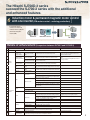 3
3
-
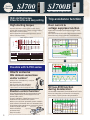 4
4
-
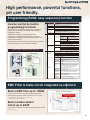 5
5
-
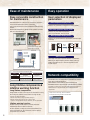 6
6
-
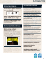 7
7
-
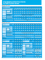 8
8
-
 9
9
-
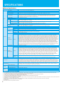 10
10
-
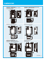 11
11
-
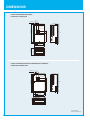 12
12
-
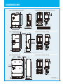 13
13
-
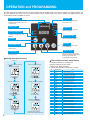 14
14
-
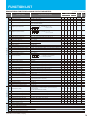 15
15
-
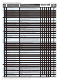 16
16
-
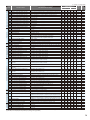 17
17
-
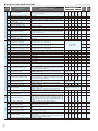 18
18
-
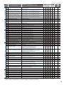 19
19
-
 20
20
-
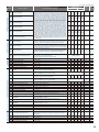 21
21
-
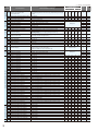 22
22
-
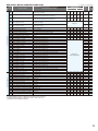 23
23
-
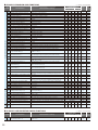 24
24
-
 25
25
-
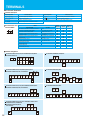 26
26
-
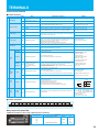 27
27
-
 28
28
-
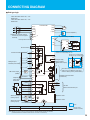 29
29
-
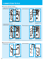 30
30
-
 31
31
-
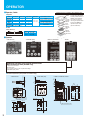 32
32
-
 33
33
-
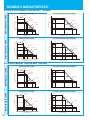 34
34
-
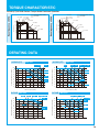 35
35
-
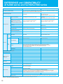 36
36
-
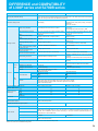 37
37
-
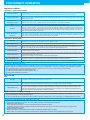 38
38
-
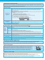 39
39
-
 40
40


Hitachi SJ700 Series Software User manual
- Category
- Power adapters & inverters
- Type
- User manual
- This manual is also suitable for
Ask a question and I''ll find the answer in the document
Finding information in a document is now easier with AI
Related papers
-
Hitachi SJ700D-550L User manual
-
-
Hitachi SJ300 User manual
-
Hitachi SJ700B SERIES Quick Reference Manual
-
-
Sharp SJ300 Series User manual
-
Hitachi SJ700B-075H User manual
-
-
-
Other documents
-
Toshiba Welding System VF-A7 User manual
-
HP 30 30 User manual
-
ACP Speecon 7200M3 User manual
-
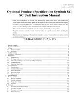 Tsubaki Small Size Gear Motor Optional Product SC Unit User manual
-
 AE-TECHNOLOGY AE-L User manual
-
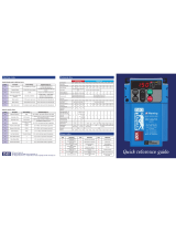 IMO Jaguar VXR2A5-4 Quick Reference Manual
-
-
Mitsubishi Electric FR-FK REMOTE SPEED SETTER Owner's manual
-
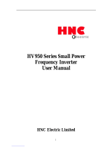 HNC Electric HV950-2R2G3 User manual
-
Hyundai N700E 037 HF User manual


