STIHL FSA 65 User manual

Type
User manual

This manual is also suitable for

Original Instruction Manual Printed on chlorine-free paper
Printing inks contain vegetable oils, paper can be recycled.
© ANDREAS STIHL AG & Co. KG, 2014
0458-284-9921-A. VA8.K14.
0000003012_011_GB
FSA 65, FSA 85
English
28
{
This instruction manual is protected by copyright. All rights reserved, especially the rights to reproduce, translate and process
with electronic systems.
Contents
Dear Customer,
Thank you for choosing a quality
engineered STIHL product.
It has been built using modern
production techniques and
comprehensive quality assurance.
Every effort has been made to ensure
your satisfaction and troublefree use of
the product.
Please contact your dealer or our sales
company if you have any queries
concerning this product.
Your
Dr. Nikolas Stihl
Guide to Using this Manual 29
Safety Precautions and Working
Techniques 29
Using the Unit 33
Approved Combinations of Cutting
Attachment and Deflector 34
Adjusting the Loop Handle 34
Mounting the Deflector 35
Adjusting Nylon Line 35
Connecting Charger to Power
Supply 36
Charging the Battery 36
LEDs on Battery 37
LED on Charger 39
Switching On 39
Switching Off 40
Storing the Machine 41
Replacing Nylon Line 41
Maintenance and Care 44
Minimize Wear and Avoid Damage 45
Main Parts 46
Specifications 47
Troubleshooting 48
Maintenance and Repairs 50
Disposal 50
EC Declaration of Conformity 50
FSA 65, FSA 85
English
29
Pictograms
All the pictograms attached to the
machine are shown and explained in this
manual.
Symbols in text
WARNING
Warning where there is a risk of an
accident or personal injury or serious
damage to property.
NOTICE
Caution where there is a risk of
damaging the machine or its individual
components.
Engineering improvements
STIHL's philosophy is to continually
improve all of its products. For this
reason we may modify the design,
engineering and appearance of our
products periodically.
Therefore, some changes, modifications
and improvements may not be covered
in this manual.
Observe all applicable local safety
regulations, standards and ordinances.
If you have not used this model before:
Have your dealer or other experienced
user show you how to operate your
machine or attend a special course in its
operation.
Minors should never be allowed to use
this product.
Keep bystanders, especially children,
and animals away from the work area.
When the machine is not in use, store it
so that it does not endanger others.
Secure it against unauthorized use.
The user is responsible for avoiding
injury to third parties or damage to their
property.
Do not lend or rent your power tool
without the instruction manual. Be sure
that anyone using it understands the
information contained in this manual.
The use of noise emitting power tools
may be restricted to certain times by
national or local regulations.
To operate this power tool you must be
rested, in good physical condition and
mental health.
If you have any condition that might be
aggravated by strenuous work, check
with your doctor before operating a
power tool.
Do not operate the power tool if you are
under the influence of any substance
(drugs, alcohol) which might impair
vision, dexterity or judgment.
Use your power tool only for cutting
grass, wild growth and similar materials.
Do not use your power tool for any other
purpose because of the increased risk of
accidents.
– before carrying out inspections,
adjustments or cleaning work
– before working on the cutting
attachment
– before leaving the machine
unattended
– before transporting the machine
– before storing the machine
– before performing repairs and
maintenance work
– in the event of danger or in an
emergency
Guide to Using this Manual Safety Precautions and
Working Techniques
Some special safety pre-
cautions have to be
observed when working
with this power tool
because of the very high
speed of the cutting
attachment.
It is important that you
read the instruction man-
ual before first use and
keep it in a safe place for
future reference. Non-
observance of the
instruction manual may
result in serious or even
fatal injury.
Remove the battery from
the power tool:
FSA 65, FSA 85
English
30
This avoids the risk of the motor starting
unintentionally.
Only use cutting attachments and
accessories that are explicitly approved
for this power tool by STIHL or are
technically identical. If you have any
questions in this respect, consult a
servicing dealer. Use only high quality
tools and accessories in order to avoid
the risk of accidents and damage to the
unit.
STIHL recommends the use of genuine
STIHL tools and accessories. They are
specifically designed to match the
product and meet your performance
requirements.
Never attempt to modify your machine in
any way since this may increase the risk
of personal injury. STIHL excludes all
liability for personal injury and damage
to property caused while using
unauthorized attachments.
The deflector on this power tool cannot
protect the operator from all objects
thrown by the cutting attachment
(stones, glass, wire, etc.). Such objects
may ricochet and then hit the operator.
Do not use a pressure washer to clean
the unit. The solid jet of water may
damage parts of the unit.
Do not spray the power tool with water.
Battery
Observe the information in the leaflet or
instruction manual supplied with the
STIHL battery and keep it in a safe
place.
For further notes on safety see
www.stihl.com/safety-data-sheets
Charger
Observe the information in the leaflet
supplied with the STIHL charger and
keep it in a safe place.
Clothing and Equipment
Wear proper protective clothing and
equipment.
Avoid clothing that could get caught on
branches or brush or moving parts of the
machine. Do not wear a scarf, necktie or
jewelry. Tie up and confine long hair
(e.g. with a hair net, cap, hard hat, etc.).
WARNING
Wear a face shield and make sure it is a
good fit. A face shield alone does not
provide adequate eye protection.
STIHL offers a comprehensive range of
personal protective clothing and
equipment.
Transporting the Power Tool
Always switch off the power tool, move
the retaining latch to Æ’ and remove the
battery – even when you carry the
machine for short distances. This avoids
the risk of the motor starting
unintentionally.
Carry the power tool properly balanced
by the shaft.
Transporting by vehicle: Properly secure
the power tool to prevent turnover and
damage.
Clothing must be sturdy
but allow complete free-
dom of movement. Wear
snug-fitting clothing, an
overall and jacket combi-
nation, do not wear a
work coat.
Wear sturdy shoes with
non-slip soles.
To reduce the risk of eye
injuries, wear snug-fitting
safety glasses in accord-
ance with European
Standard EN 166. Make
sure the safety glasses
are a good fit.
Wear robust work gloves
made of durable material
(e.g. leather).
3905BA000 KN
FSA 65, FSA 85
English
31
Before Starting Work
Check that your power tool is properly
assembled and in good condition – refer
to appropriate chapters in the instruction
manual.
– The trigger switch and trigger
lockout must move freely (retaining
latch to ‚) – switches must return to
the idle position when they are
released.
– Use only an approved combination
of cutting attachment, deflector and
handle. All parts must be
assembled properly and securely.
To reduce the risk of injury, never
use metal cutting attachments.
– Check that the cutting attachment is
properly and securely mounted and
in good condition.
– Check protective devices (e.g.
deflector for cutting attachment) for
damage or wear. Always replace
damaged parts. Never operate the
unit with a damaged deflector.
– Never attempt to modify the controls
or safety devices in any way.
– Keep the handles dry and clean –
free from oil and dirt – for safe
control of the power tool.
– Check contacts in battery
compartment for foreign matter.
– Fit the battery correctly – it must
engage audibly.
– Never use defective or deformed
batteries.
To reduce the risk of accidents, do not
operate the unit if it is not properly
assembled and in good condition.
Before switching on the power tool,
make sure the cutting attachment is not
touching the ground or any other object.
Holding and Controlling the Power Tool
Always hold the unit firmly with both
hands on the handles. Make sure you
always have good balance and secure
footing.
Right-handers
Left hand on the loop handle and right
hand on the control handle.
Left-handers
Right hand on the loop handle and left
hand on the control handle.
During Operation
In case of imminent danger or in an
emergency, switch off the motor
immediately, move retaining latch to Æ’
and remove the battery.
The cutting attachment may catch and
fling objects a great distance and cause
injury - therefore, do not allow any other
persons within a radius of 15 meters of
your own position. To reduce the risk of
damage to property, also maintain this
distance from other objects (vehicles,
windows). Even maintaining a distance
of 15 meters or more cannot exclude the
potential danger.
To reduce the risk of
injury, avoid contact with
the cutting attachment.
Note that the cutting
attachment continues to
run for a short period
after the power tool is
switched off – flywheel
effect.
3905BA001 KN
3905BA026 KN
15m (50ft)
FSA 65, FSA 85
English
32
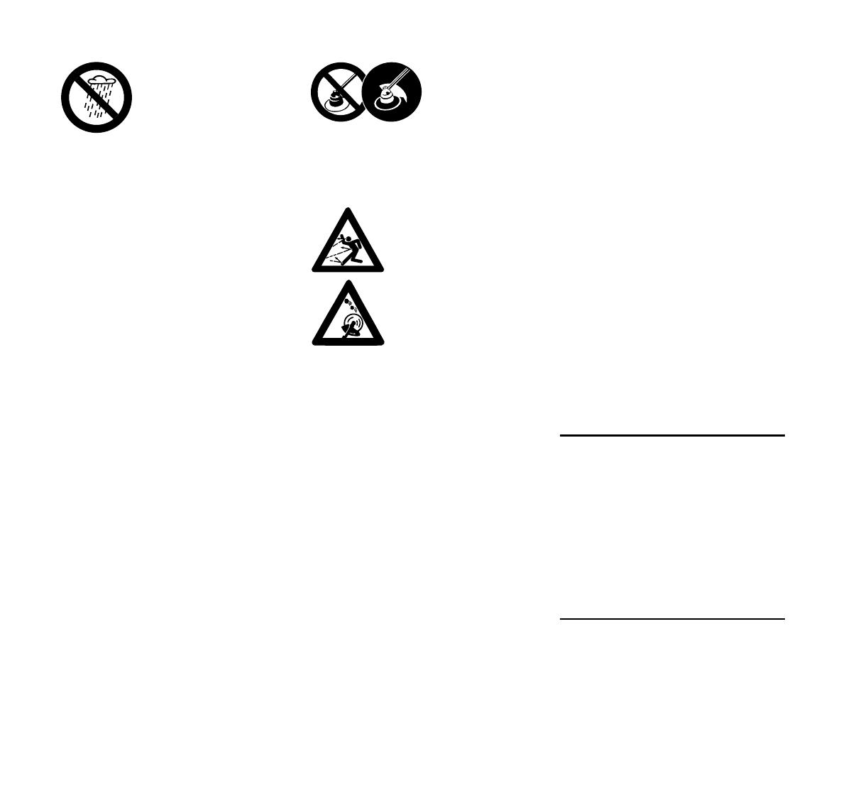
Do not leave the power tool outdoors in
the rain.
Do not cut wet grass.
Take special care in slippery conditions
(ice, wet ground, snow), on slopes or
uneven ground.
Watch out for obstacles: Roots and tree
stumps which could cause you to trip or
stumble.
To reduce the risk of accidents, take a
break in good time to avoid tiredness or
exhaustion.
Work calmly and carefully – in daylight
conditions and only when visibility is
good. Stay alert so as not to endanger
others.
If your power tool is subjected to
unusually high loads for which it was not
designed (e.g. heavy impact or a fall),
always check that it is in good condition
before continuing work – see also
"Before Starting Work". Make sure the
safety devices are working properly. Do
not continue operating your power tool if
it is damaged. In case of doubt, consult
your servicing dealer.
Special care must be taken when
working in difficult, over-grown terrain.
The dust that occurs during operation
may be harmful to health. If dust levels
are very high, wear a suitable respirator.
Before leaving the power tool
unattended: Always switch off the power
tool, set the retaining latch to Æ’ and
remove the battery.
Check the cutting attachment at regular
short intervals during operation or
immediately if there is a noticeable
change in cutting behavior:
– Switch off the motor, move the
retaining latch to Æ’ and wait for the
cutting attachment to come to a
standstill, remove the battery.
– Check condition and tightness, look
for cracks.
Clean grass and plant residue off the
cutting attachment mounting at regular
intervals – remove any build up of
material from the cutting attachment and
deflector.
To replace the cutting attachment,
switch off the power tool, move the
retaining latch to Æ’ and remove the
battery. This avoids the risk of injury
from the motor starting unintentionally.
Never continue using or attempt to
repair damaged or cracked cutting
attachments.
This may cause parts of the cutting
attachment to come off and hit the
operator or bystanders at high speed
and result in serious or fatal injuries.
Use only the deflector with properly
mounted line limiting blade to ensure the
mowing lines are automatically trimmed
to the approved length.
After Finishing Work
Always clean dust and dirt off the power
tool with a cloth – do not use any grease
solvents for this purpose.
Do not spray the mowing head or
deflector with water or immerse them in
water as this may damage the drive
motor and electronic control unit in the
motor housing.
Vibrations
This power tool minimizes the vibrations
transmitted to the operator's hands.
The drive motor is not
waterproof. Never work
with the machine in the
rain or in wet or very
damp locations.
To reduce the risk
of injury from
thrown objects,
never operate the
power tool without
the proper deflec-
tor for the type of
cutting attachment
being used.
Inspect the work area:
Stones, pieces of metal
or other solid objects may
be thrown more than 15
meters and cause per-
sonal injury or damage
the cutting attachment
and property (e.g. parked
vehicles, windows).
FSA 65, FSA 85
English
33
However, the operator should seek
medical advice in the event of suspected
circulatory problems in the hands (e.g.
tingling sensation in the fingers).
Maintenance and Repairs
Always move the retaining latch to Æ’
and remove the battery before carrying
out any repairs or maintenance work on
the power tool. This avoids the risk of
the motor starting unintentionally.
Service the machine regularly. Do not
attempt any maintenance or repair work
not described in the instruction manual.
Have all other work performed by a
servicing dealer.
STIHL recommends that you have
servicing and repair work carried out
exclusively by an authorized STIHL
servicing dealer. STIHL dealers are
regularly given the opportunity to attend
training courses and are supplied with
the necessary technical information.
Only use high-quality replacement parts
in order to avoid the risk of accidents
and damage to the unit. If you have any
questions in this respect, consult a
servicing dealer.
STIHL recommends the use of genuine
STIHL replacement parts. They are
specifically designed to match your
model and meet your performance
requirements.
Never attempt to modify your power tool
in any way since this will increase the
risk of personal injury.
Regularly check the electrical contacts
and ensure that the insulation of the
connecting cord and plug of the charger
is in good condition and shows no sign
of ageing (brittleness).
Electrical components, e.g. connecting
cord of charger, may only be repaired or
replaced by a qualified electrician.
Clean plastic components with a cloth.
Do not use aggressive detergents. They
may damage the plastic.
Check tightness of mounting screws on
safety devices and the cutting
attachment and retighten if necessary.
Clean cooling air inlets in motor housing
as necessary.
Keep the battery guides free from
foreign matter – clean as necessary.
Store the power tool in a dry, locked
location with the retaining latch on Æ’
and the battery removed.
Mowing
N Hold the unit with both hands – one
hand on the control handle – one
hand on the loop handle.
N Stand upright – hold the power tool
in a relaxed position.
N Make sure the cutting attachment is
not touching the ground or any other
objects.
N Swing the trimmer back and forth in
an arc.
N The cutting height is determined by
the distance of the mowing line from
the lawn surface.
N Avoid contact with fences, walls,
rocks, etc. since it will result in a
higher rate of wear.
Using the Unit
3905BA002 KN
FSA 65, FSA 85
English
34
Working with bump guard
The bump guard comes standard with
the FSA 85. It is available as a special
accessory for the FSA 65.
The bump guard (1)
– Limits the cutting range of the
mowing line
– reduces the risk of the rotating
mowing line causing damage (e.g.
tree bark)
WARNING
The mowing head may continue to
rotate briefly after you switch off your
power tool – wait for the mowing head to
come to a standstill before adjusting the
bump guard – do not adjust it with your
foot.
Disposal
N Do not throw cuttings into the
garbage can – they can be
composted.
Cutting attachment
The trimmer comes from the factory with
the AutoCut C 4-2 mowing head already
fitted. For safety reasons no other
cutting attachments may be mounted to
the trimmer.
Deflector
The trimmer is supplied with a deflector.
Only this deflector may be mounted to
the trimmer – no other deflectors are
permitted. For further information see
"Mounting the Deflector".
Your new power tool comes with the
loop handle mounted on the drive tube,
but it must be turned and lined up to suit
your requirements.
N Loosen the star knob (1) on the
handle.
N Turn the handle to the vertical
position.
1
3905BA003 KN
Approved Combinations of
Cutting Attachment and
Deflector
3905BA004 KN
Adjusting the Loop Handle
1
3905BA005 KN
3905BA006 KN
FSA 65, FSA 85
English
35
The loop handle can be adjusted to suit
the height and reach of the operator and
the application by changing
distance (A).
Recommendation: distance (A):
about 10 cm
N Slide the handle to the required
position.
N Tighten down the star knob so that
the handle cannot be rotated on the
shaft.
N Position your trimmer so that the
mowing head (1) faces up.
The motor housing has guide slots
(arrows) to correctly locate the deflector.
N Push the deflector (2) into the guide
slots as far as stop.
N Insert the screws (3) and tighten
them down firmly.
Adjusting Nylon Line
N Hold the rotating mowing head
above the ground – tap it on the
ground once – about 3 cm fresh line
is advanced.
The blade (1) on the deflector (2) trims
surplus line to the correct length – avoid
tapping the mowing head more than
once at a time.
Line feed operates only if both lines still
have a minimum length of 2.5 cm.
If the line is shorter than 2.5 cm:
N Switch off the trimmer.
N Move the retaining latch to Æ’ and
remove the battery.
N Turn the trimmer on its back.
N Press down the cap on the spool as
far as stop.
N Pull the ends of the lines out of the
spool.
If the spool is empty, see "Replacing
Nylon Line".
3905BA007 KN
A
Mounting the Deflector
1
3905BA008 KN
3
2
3
3905BA009 KN
Adjusting Nylon Line
1
2
3905BA010 KN
FSA 65, FSA 85
English
36
Power supply (mains) voltage and
operating voltage must be the same.
N Insert the plug (1) in the wall
outlet (2).
A self test is performed after the charger
is connected to the power supply. During
this process, the light emitting diode (1)
on the charger lights up green for about
1 second, then red and goes off again.
A factory-new battery is not fully
charged.
Recommendation: Fully charge the
battery before using it for the first time.
N Connect the charger to the power
supply – mains voltage and
operating voltage of the charger
must be the same – see
"Connecting Charger to Power
Supply".
Operate the charger only in enclosed
and dry rooms at ambient temperatures
between +5°C to +40°C (+41°F to
+104°F)
Only charge dry batteries. Allow a damp
battery to dry before charging.
N Push the battery (1) into the
charger (2) until noticeable
resistance is felt – then push it as far
as stop.
The LED (3) on the charger comes on
when the battery is inserted – see "LED
on Charger"
Charging begins as soon as the
LEDs (4) on the battery glow green –
see "LEDs on Battery".
The charge time is dependent on a
number of factors, including battery
condition, ambient temperature, etc.,
and may therefore vary from the times
specified.
The battery heats up during operation in
the power tool. If a hot battery is inserted
in the charger, it may be necessary to
cool it down before charging. The
charging process begins only after the
battery has cooled down. The time
required for cooling may prolong the
charge time.
The battery and charger heat up during
the charging process.
AL 300, AL 500 Chargers
The AL 300 and AL 500 chargers are
equipped with a battery cooling fan
Connecting Charger to
Power Supply
3901BA015 KN
2
1
1
3901BA019 KN
Charging the Battery
2
3901BA009 KN
4
3901BA014 KN
3
FSA 65, FSA 85
English
37
AL 100 Charger
The AL 100 charger has no fan and
waits for the battery to cool down before
starting the charging process. The
battery is cooled by heat transfer to the
ambient air.
End of Charge
The charger switches itself off
automatically when the battery is fully
charged:
– LEDs on the battery go off.
– The LED on the charger goes off.
– The charger's fan is switched off (if
charger is so equipped)
Remove the fully charged battery from
the charger.
Four LEDs show the battery's state of
charge and any problems that occur on
the battery or power tool.
N Press button (1) to activate the
display – the display goes off
automatically after 5 seconds.
The LEDs can glow or flash green or
red.
During Charging Process
The LEDs glow continuously or flash to
indicate the progress of charge.
A green flashing LED indicates the
capacity that is currently being charged.
The light emitting diodes on the battery
go off automatically when the charge
process is completed.
If the LEDs on the battery flash or glow
red – see "If the red LEDs glow
continuously / flash".
LEDs on Battery
LED glows continuously green.
LED flashes green.
LED glows continuously red.
LED flashes red.
1
3901BA010 KN
3901BA018 KN
80 - 100 %
60 - 80 %
40 - 60 %
20 - 40 %
0 - 20 %
FSA 65, FSA 85
English
38
During Operation
The green LEDs glow continuously or
flash to indicate the state of charge.
If the LEDs on the battery flash or glow
red – see "If the red LEDs glow
continuously / flash".
If the red LEDs glow continuously / flash
3901BA016 KN
80 - 100 %
60 - 80 %
40 - 60 %
20 - 40 %
0 - 20 %
A 1 LED glows
continuously
red:
Battery is too
hot
1) 2)
/cold
1)
1)
When charging: Charge process
starts automatically after the battery
has cooled down / warmed up.
2)
During operation: Power tool cuts
out – allow battery to cool down; it
may be necessary to take the
battery out of the power tool for this
purpose.
B 4 LEDs flash
red
Malfunction in
battery
3)
C 3 LEDs glow
continuously
red:
Power tool is too
hot – allow it to
cool down.
D 3 LEDs flash
red
Malfunction in
power tool
4)
3901BA041 KN
A
B
C
D
3)
Electromagnetic interference or
fault. Take the battery out of the
power tool and refit it. Switch on the
machine – if the LEDs continue to
flash, the battery has a malfunction
and must be replaced.
4)
Electromagnetic interference or
fault. Take the battery out of the
machine. Use a blunt tool to
remove dirt from the contacts in the
battery compartment. Refit the
battery. Switch on the power tool –
if the light emitting diodes still flash,
the power tool is faulty and must be
checked by a servicing dealer –
STIHL recommends an authorized
STIHL servicing dealer.
FSA 65, FSA 85
English
39
The LED (1) on the charger may glow
continuously green or flash red.
Green continuous light ...
... indicates the following:
The battery
– is being charged
– is too hot and must cool down
before charging
See also "LEDs on battery".
The green LED on the charger goes off
as soon as the battery is fully charged.
Red flashing light ...
... may indicate the following:
– No electrical contact between
battery and charger – remove and
refit the battery
– Malfunction in battery – see also
"LEDs on Battery".
– Malfunction in charger – have
checked by a servicing dealer.
STIHL recommends an authorized
STIHL servicing dealer.
A factory-new battery is not fully
charged.
Recommendation: Fully charge the
battery before using it for the first time.
N If necessary, remove the cover from
the battery compartment before
fitting the battery, i.e. depress both
locking tabs to unlock and remove
the cover.
Fitting the Battery
N Insert the battery (1) in the power
tool – the battery slides into the
compartment – press it down
carefully until it snaps into position –
the battery must be flush with the
top of the housing.
Switching on the Machine
N Make sure you have a secure and
firm footing.
N Stand upright – hold the power tool
in a relaxed position.
N Make sure the cutting attachment is
not touching the ground or any other
objects.
N Hold the power tool with both hands
– one hand on the control handle –
one hand on the loop handle.
N Unlock the power tool by moving the
retaining latch (2) to ‚.
N Push down the trigger switch
lockout (3) and depress the trigger
switch (4) and hold them in that
position.
The motor runs only if the retaining
latch (2) is on ‚ and the trigger switch
lockout (3) and trigger switch (4) are
operated simultaneously.
LED on Charger
1
3901BA019 KN
Switching On
1
3905BA011 KN
2
3905BA012 KN
4
3
2
3905BA013 KN
FSA 65, FSA 85
English
40
Trigger
Motor speed can be controlled with the
trigger switch. Motor speed is increased
progressively by squeezing the trigger
switch (FSA 85 only).
N Release the trigger switch
lockout (1) and the trigger
switch (2).
N Move the retaining latch (3) to ƒ –
the trigger switch (2) cannot be
operated – the power tool is locked
to prevent start-up.
Always remove the battery from the
power tool during work breaks and after
finishing work.
Removing the battery
N Press in both locking tabs (4) at the
same time to unlock the battery (5).
N Take the battery (5) out of the
housing.
When the power tool is not in use, shut it
off so that it does not endanger others.
Secure it against unauthorized use.
Switching Off
2
1
3905BA014 KN
3
3905BA015 KN
2
4
4
3905BA016 KN
FSA 65, FSA 85
English
41
N Move the retaining latch to Æ’.
N Remove the battery.
N Thoroughly clean the machine.
N Store the machine in a dry and
secure location out of the reach of
children and other unauthorized
persons.
Cover for Battery Compartment
In some markets the machine comes
with a cover for the battery
compartment. It protects the battery
compartment from contamination.
N After finishing work, slide the
cover (1) home until it engages
audibly in position.
Storing the Battery
N Take the battery out of the power
tool or the charger.
N Store indoors in a dry and safe
location. Keep out of the reach of
children and other unauthorized
persons and protected from
contamination.
N Do not store spare batteries unused
– use in rotation.
To optimize the life of the battery, store
it at a state of charge of about 30%.
Storing the Charger
N Remove the battery.
N Disconnect the plug from the wall
outlet.
N Store the charger indoors in a dry
and secure location. Keep out of the
reach of children and other
unauthorized persons and
protected from contamination.
STIHL AutoCut C 4-2
Always check the mowing head for signs
of wear before replacing the nylon line.
WARNING
If there are signs of serious wear,
replace the complete mowing head.
Preparations
N Switch off the trimmer.
N Move the retaining latch to Æ’.
N Remove the battery
N Put the power tool on the ground
with the mowing head facing up.
Removing the mowing head and
remaining nylon line
In normal operation, the supply of nylon
line in the head is used up almost
completely.
Storing the Machine
3905BA027 KN
1
Replacing Nylon Line
FSA 65, FSA 85
English
42
N Hold the mowing head steady and
rotate the cap (1) counterclockwise
until it can be removed.
N Remove the mowing head.
N Pull the spool (2) out of the mowing
head (3) and remove the remaining
line.
Assembling the mowing head
N Fit the empty spool in the mowing
head (3).
If the spring (4) has popped out:
N Push the spring into the spool (2) as
far as stop.
Winding line onto spool
N Use green-coded nylon line with a
diameter of 2.0 mm.
N Cut two 2.5 m lengths of line from
the replacement reel (special
accessory).
N Rotate the spool (2)
counterclockwise until the two arrow
points are in alignment.
N Push the straight end of each line
through one sleeve (5) in the
mowing head (3) until you feel a
noticeable resistance – and then
continue pushing as far as stop.
3905BA017 KN
2
3
1
3905BA018 KN
2
3
4
3
5
3905BA019 KN
3
FSA 65, FSA 85
English
43
N Hold the mowing head steady.
N Rotate the spool counterclockwise
until the shortest line is about
10 cm.
N If necessary, cut the longer line to a
length of about 10 cm.
The mowing head is now full.
Mounting the Mowing Head
N Slip the mowing head (6) over the
shaft (7) and engage hex recess (8)
on the external hexagon (9).
N Turn the spool (2) clockwise until
the two arrow heads line up –
secure the spool in this position.
N Insert the cap (1) in the spool (2),
press it down as far as stop and turn
it clockwise at the same time.
N Turn the cap (1) as far as stop and
tighten it down by hand.
3905BA020 KN
8
6
9
3905BA021 KN
7
1
2
3905BA022 KN
FSA 65, FSA 85
English
44
Maintenance and Care
The following intervals apply to normal operating conditions only. If your daily work-
ing time is longer or operating conditions are difficult (very dusty work area, etc.),
shorten the specified intervals accordingly.
Move the retaining latch to
Æ’ before performing any work on the power tool.
before starting work
after finishing work or daily
weekly
monthly
every 12 months
if problem
if damaged
if required
Complete machine
Visual inspection (condition) X
Clean X
Controls (retaining latch, trigger switch
lockout, trigger switch)
Check operation X
Clean XX
All accessible screws and nuts Retighten X
Battery Visual inspection XXX
Battery compartment
Clean X X
Check operation (eject battery) X
Cutting attachment (mowing head)
Visual inspection X
Replace X
Check tightness X
Safety labels Replace X
FSA 65, FSA 85
English
45
Observing the instructions in this manual
helps reduce the risk of unnecessary
wear and damage to the power tool.
The power tool must be operated,
maintained and stored with the due care
and attention described in this
instruction manual.
The user is responsible for all damage
caused by non-observance of the safety
precautions, operating and maintenance
instructions. This includes in particular:
– Alterations or modifications to the
product not approved by STIHL.
– Using tools or accessories which
are neither approved or suitable for
the product or are of a poor quality.
– Using the product for purposes for
which it was not designed.
– Using the product for sports or
competitive events.
– Consequential damage caused by
continuing to use the product with
defective components.
Maintenance Work
All the operations described in the
chapter on "Maintenance and Care"
must be performed on a regular basis. If
these maintenance operations cannot
be performed by the owner, they should
be performed by a servicing dealer.
STIHL recommends that you have
servicing and repair work carried out
exclusively by an authorized STIHL
servicing dealer. STIHL dealers are
regularly given the opportunity to attend
training courses and are supplied with
the necessary technical information.
If these maintenance operations are not
carried out as specified, the user
assumes responsibility for any damage
that may occur. Among other things,
this includes:
– Damage to the motor due to neglect
or deficient maintenance.
– Damage to the charger caused by
incorrect electrical connection
(voltage).
– Corrosion and other consequential
damage to the machine, battery and
charger due to improper storage
and use.
– Damage to the product resulting
from the use of poor quality
replacement parts.
Parts Subject to Wear and Tear
Some parts of the power tool are subject
to normal wear and tear even during
regular operation in accordance with
instructions and, depending on the type
and duration of use, have to be replaced
in good time. Among other parts, this
includes:
– Cutting attachment
– Deflector
– Battery
Minimize Wear and Avoid
Damage
FSA 65, FSA 85
English
46
1 Battery compartment
2 Control handle
3 Trigger switch lockout
4 Trigger switch
5 Retaining latch
6 Loop handle
7 Star knob
8 Shaft
9 Battery locking tabs
10 Battery
11 Light emitting diodes (LEDs) on
battery
12 Pushbutton for activating LEDs on
battery
13 Mowing head
14 Line limiter blade
15 Deflector
16 Charger
17 LED on charger
18 Connecting cord with plug
# Serial number
Main Parts
14
15
#
18
5
4
3
17
16
3905BA023 KN
1
2
6
7
8
9
10
9
12
11
13
FSA 65, FSA 85
English
47
Battery
The machine may be operated only with
original STIHL rechargeable batteries.
Running time is dependent on the
energy content of the battery.
Cutting Attachment
Length
Weight
Noise and Vibration Data
Noise and vibration data are determined
on the basis of the rated maximum
speed.
For further details on compliance with
Vibration Directive 2002/44/EC see
www.stihl.com/vib/
Sound pressure level L
p
to EN 786
Sound power level L
w
to EN 786
Vibration measurement a
hv
to EN 786
The K-factor in accordance with
Directive 2006/42/EC is 2.5 dB(A) for
the sound pressure level and sound
power level; the K-factor in accordance
with Directive 2006/42/EC is 2.0 m/s
2
for the vibration measurement.
The vibration values quoted above have
been measured according to a
standardized test procedure and may be
used to compare electric power tools.
Depending on the type of usage, the
vibrations that actually occur may differ
from the values quoted.
The vibration values quoted may be
used for an initial assessment of the
user's exposure to vibrations.
The actual exposure to vibrations has to
be evaluated. This process may also
take into account times during which the
electric power tool is switched off and
times during which it is switched on but
running without load.
Transport
STIHL batteries fulfill the requirements
stated in UN-Manual
ST/SG/AC.10/11/Rev.5 Part III,
Subsection 38.3.
The user can transport STIHL batteries
by road transport to the place where the
machine is to be used without additional
requirements.
The lithium ion batteries included are
subject to the provisions of the
legislation relating to dangerous goods.
When shipped by a third party (e. g. air
transport or haulage firm), special
packaging and identification
requirements must be observed.
When preparing the item for shipment, a
dangerous goods expert must be
consulted. Please observe any further
national regulations.
Pack the battery so that it cannot move
inside the packaging.
Further transport instructions - see
www.stihl.com/safety-data-sheets
REACH
REACH is an EC regulation and stands
for the Registration, Evaluation,
Authorisation and Restriction of
Chemical substances.
For information on compliance with the
REACH regulation (EC) No. 1907/2006
see www.stihl.com/reach.
Specifications
Type: Lithium-ion
Category: AP, AR
Cutting swath:
FSA 65: 300 mm
FSA 85: 350 mm
FSA 65: 1530 mm
FSA 85: 1650 mm
without battery, with cutting attachment
and deflector
FSA 65: 2.7 kg
FSA 85: 2.8 kg
FSA 65: 75 dB(A)
FSA 85: 77 dB(A)
FSA 65: 89 dB(A)
FSA 85: 92 dB(A)
Handle, left Handle, right
FSA 65: 1.3 m/s
2
1.1 m/s
2
FSA 85: 1.4 m/s
2
0.8 m/s
2
  • Page 1 1
  • Page 2 2
  • Page 3 3
  • Page 4 4
  • Page 5 5
  • Page 6 6
  • Page 7 7
  • Page 8 8
  • Page 9 9
  • Page 10 10
  • Page 11 11
  • Page 12 12
  • Page 13 13
  • Page 14 14
  • Page 15 15
  • Page 16 16
  • Page 17 17
  • Page 18 18
  • Page 19 19
  • Page 20 20
  • Page 21 21
  • Page 22 22
  • Page 23 23
  • Page 24 24
  • Page 25 25
  • Page 26 26
  • Page 27 27
  • Page 28 28
  • Page 29 29
  • Page 30 30
  • Page 31 31
  • Page 32 32
  • Page 33 33
  • Page 34 34
  • Page 35 35
  • Page 36 36
  • Page 37 37
  • Page 38 38
  • Page 39 39
  • Page 40 40
  • Page 41 41
  • Page 42 42
  • Page 43 43
  • Page 44 44
  • Page 45 45
  • Page 46 46
  • Page 47 47
  • Page 48 48
  • Page 49 49
  • Page 50 50
  • Page 51 51
  • Page 52 52
  • Page 53 53
  • Page 54 54
  • Page 55 55
  • Page 56 56
  • Page 57 57
  • Page 58 58
  • Page 59 59
  • Page 60 60
  • Page 61 61
  • Page 62 62
  • Page 63 63
  • Page 64 64
  • Page 65 65
  • Page 66 66
  • Page 67 67
  • Page 68 68
  • Page 69 69
  • Page 70 70
  • Page 71 71
  • Page 72 72
  • Page 73 73
  • Page 74 74
  • Page 75 75
  • Page 76 76
  • Page 77 77
  • Page 78 78
  • Page 79 79
  • Page 80 80
  • Page 81 81
  • Page 82 82
  • Page 83 83
  • Page 84 84
  • Page 85 85
  • Page 86 86
  • Page 87 87
  • Page 88 88
  • Page 89 89
  • Page 90 90
  • Page 91 91
  • Page 92 92
  • Page 93 93
  • Page 94 94
  • Page 95 95
  • Page 96 96
  • Page 97 97
  • Page 98 98
  • Page 99 99
  • Page 100 100
  • Page 101 101
  • Page 102 102
  • Page 103 103
  • Page 104 104
  • Page 105 105
  • Page 106 106
  • Page 107 107
  • Page 108 108
  • Page 109 109
  • Page 110 110
  • Page 111 111
  • Page 112 112
  • Page 113 113
  • Page 114 114
  • Page 115 115
  • Page 116 116
  • Page 117 117
  • Page 118 118
  • Page 119 119
  • Page 120 120
  • Page 121 121
  • Page 122 122
  • Page 123 123
  • Page 124 124
  • Page 125 125
  • Page 126 126
  • Page 127 127
  • Page 128 128
  • Page 129 129
  • Page 130 130
  • Page 131 131
  • Page 132 132
  • Page 133 133
  • Page 134 134
  • Page 135 135
  • Page 136 136
  • Page 137 137
  • Page 138 138
  • Page 139 139
  • Page 140 140
  • Page 141 141
  • Page 142 142
  • Page 143 143
  • Page 144 144
  • Page 145 145
  • Page 146 146
  • Page 147 147
  • Page 148 148
  • Page 149 149
  • Page 150 150
  • Page 151 151
  • Page 152 152
  • Page 153 153
  • Page 154 154
  • Page 155 155
  • Page 156 156
  • Page 157 157
  • Page 158 158
  • Page 159 159
  • Page 160 160
  • Page 161 161
  • Page 162 162
  • Page 163 163
  • Page 164 164
  • Page 165 165
  • Page 166 166
  • Page 167 167
  • Page 168 168
  • Page 169 169
  • Page 170 170
  • Page 171 171
  • Page 172 172
  • Page 173 173
  • Page 174 174
  • Page 175 175
  • Page 176 176
  • Page 177 177
  • Page 178 178
  • Page 179 179
  • Page 180 180
  • Page 181 181
  • Page 182 182
  • Page 183 183
  • Page 184 184
  • Page 185 185
  • Page 186 186
  • Page 187 187
  • Page 188 188
  • Page 189 189
  • Page 190 190
  • Page 191 191
  • Page 192 192
  • Page 193 193
  • Page 194 194
  • Page 195 195
  • Page 196 196
  • Page 197 197
  • Page 198 198
  • Page 199 199
  • Page 200 200
  • Page 201 201
  • Page 202 202
  • Page 203 203
  • Page 204 204
  • Page 205 205
  • Page 206 206
  • Page 207 207
  • Page 208 208
  • Page 209 209
  • Page 210 210
  • Page 211 211
  • Page 212 212
  • Page 213 213
  • Page 214 214
  • Page 215 215
  • Page 216 216
  • Page 217 217
  • Page 218 218
  • Page 219 219
  • Page 220 220
  • Page 221 221
  • Page 222 222
  • Page 223 223
  • Page 224 224
  • Page 225 225
  • Page 226 226
  • Page 227 227
  • Page 228 228
  • Page 229 229
  • Page 230 230
  • Page 231 231
  • Page 232 232
  • Page 233 233
  • Page 234 234
  • Page 235 235
  • Page 236 236
  • Page 237 237
  • Page 238 238
  • Page 239 239
  • Page 240 240
  • Page 241 241
  • Page 242 242
  • Page 243 243
  • Page 244 244
  • Page 245 245
  • Page 246 246
  • Page 247 247
  • Page 248 248
  • Page 249 249
  • Page 250 250
  • Page 251 251
  • Page 252 252
  • Page 253 253
  • Page 254 254
  • Page 255 255
  • Page 256 256
  • Page 257 257
  • Page 258 258
  • Page 259 259
  • Page 260 260
  • Page 261 261
  • Page 262 262
  • Page 263 263
  • Page 264 264
  • Page 265 265
  • Page 266 266
  • Page 267 267
  • Page 268 268
  • Page 269 269
  • Page 270 270
  • Page 271 271
  • Page 272 272
  • Page 273 273
  • Page 274 274
  • Page 275 275
  • Page 276 276
  • Page 277 277
  • Page 278 278
  • Page 279 279
  • Page 280 280
  • Page 281 281
  • Page 282 282
  • Page 283 283
  • Page 284 284
  • Page 285 285
  • Page 286 286
  • Page 287 287
  • Page 288 288
  • Page 289 289
  • Page 290 290
  • Page 291 291
  • Page 292 292
  • Page 293 293
  • Page 294 294
  • Page 295 295
  • Page 296 296
  • Page 297 297
  • Page 298 298
  • Page 299 299
  • Page 300 300
  • Page 301 301
  • Page 302 302
  • Page 303 303
  • Page 304 304
  • Page 305 305
  • Page 306 306
  • Page 307 307
  • Page 308 308
  • Page 309 309
  • Page 310 310
  • Page 311 311
  • Page 312 312
  • Page 313 313
  • Page 314 314
  • Page 315 315
  • Page 316 316
  • Page 317 317
  • Page 318 318
  • Page 319 319
  • Page 320 320
  • Page 321 321
  • Page 322 322
  • Page 323 323
  • Page 324 324
  • Page 325 325
  • Page 326 326
  • Page 327 327
  • Page 328 328
  • Page 329 329
  • Page 330 330
  • Page 331 331
  • Page 332 332
  • Page 333 333
  • Page 334 334
  • Page 335 335
  • Page 336 336
  • Page 337 337
  • Page 338 338
  • Page 339 339
  • Page 340 340
  • Page 341 341
  • Page 342 342
  • Page 343 343
  • Page 344 344
  • Page 345 345
  • Page 346 346
  • Page 347 347
  • Page 348 348
  • Page 349 349
  • Page 350 350
  • Page 351 351
  • Page 352 352
  • Page 353 353
  • Page 354 354
  • Page 355 355
  • Page 356 356
  • Page 357 357
  • Page 358 358
  • Page 359 359
  • Page 360 360

STIHL FSA 65 User manual

Type
User manual
This manual is also suitable for

Ask a question and I''ll find the answer in the document

Finding information in a document is now easier with AI