Page is loading ...

Lutron Technical Support Center 1.800.523.9466 24 hrs / 7 days www.lutron.com
Installation
For installations involving more than one control in a wallbox, refer to Multi-Unit
Installations before beginning.
Model Number No sides removed 1 side removed 2 sides removed
AY-600P / TG-600P 600 W 500 W 400 W
AYLV-600P* 600 VA/450 W* 500 VA/400 W* 400 VA/300 W*
Lutron Electronics Co., Inc.
7200 Suter Road
Coopersburg, PA 18036-1299, U.S.A.
Made and printed in U.S.A. 4/10 P/N 030-1273 Rev. A
Important Notes
Please read before installing.
1. CAUTION: Use “AY-” or “TG-” models only with permanently-installed
120 V incandescent or halogen fixtures. To avoid overheating and
possible damage to other equipment, do not use to control receptacles,
fluorescent lighting fixtures, motor-driven appliances, or transformer-supplied
appliances. Use “AYLV-” models only with core and coil (magnetic) low-voltage
transformers. To control solid state (electronic) low-voltage transformers, use
electronic low-voltage dimmers by Lutron
®.
2. CAUTION: Operating magnetic low-voltage fixtures with all lamps
inoperative or removed may result in current flow in excess of normal
levels. To avoid possible transformer overheating and premature failure,
Lutron strongly recommends the following:
• Do not operate magnetic low-voltage fixtures without operative lamps in place.
• Replace burned-out lamps immediately.
• Use magnetic low-voltage fixtures with thermal protection or fused primary
windings to prevent transformer failure due to excess current.
3. When no “grounding means” exist within the wallbox then the NEC® 2008,
Article 404.9 allows a dimmer without a grounding connection to be installed
as a replacement, as long as a plastic, noncombustible wallplate is used. For
this type of installation, cap or remove the green ground wire on the dimmer
and use an appropriate wallplate such as Fassada
® series wallplates by
Lutron
.
4. Recommended minimum load is 40 W.
5. Protect dimmer from dust and dirt when painting or spackling.
6. Dimmer and wallplate screws may feel warm to the touch during normal operation.
7. For new installations, install a test switch before installing the dimmer.
8. Install in accordance with all national and local electrical codes.
9. Clean dimmer with a
soft damp cloth only
. Do not use any chemical cleaners.
ON
OFF
ON
OFF
ON
OFF
Align dimmer and tighten
screws clockwise.
Turn screws clockwise
to start.
Backwired:
Insert screwdriver and pull wire out.
OR
Backwire Holes: Insert wires fully.
NOTE: Backwire holes are for use with
14 AWG (1.5 mm
2
)
solid copper wire only.
For aluminum wire, consult an electrician.
DO NOT use stranded or twisted wire.
Screw Terminals: Tighten securely. Screw
terminals are for use with
solid copper wire
only.
For aluminum wire, consult an electrician.
DO NOT use stranded or twisted wire.
OR
Ground
(Green screw)
ON
OFF
ON
OFF
ON
OFF
Limited Warranty (Valid only in U.S.A., Canada, Puerto Rico, and the Caribbean.)
Lutron will, at its option, repair or replace any unit that is defective in materials or manufacture within one year after purchase. For warranty service, return unit to place
of purchase or mail to Lutron at 7200 Suter Rd., Coopersburg, PA 18036-1299, postage pre-paid.
THIS WARRANTY IS IN LIEU OF ALL OTHER EXPRESS WARRANTIES, AND THE IMPLIED WARRANTY OF MERCHANTABILITY IS LIMITED TO ONE YEAR FROM
PURCHASE. THIS WARRANTY DOES NOT COVER THE COST OF INSTALLATION, REMOVAL OR REINSTALLATION, OR DAMAGE RESULTING FROM MISUSE, ABUSE,
OR DAMAGE FROM IMPROPER WIRING OR INSTALLATION. THIS WARRANTY DOES NOT COVER INCIDENTAL OR CONSEQUENTIAL DAMAGES. LUTRON’S
LIABILITY ON ANY CLAIM FOR DAMAGES ARISING OUT OF OR IN CONNECTION WITH THE MANUFACTURE, SALE, INSTALLATION, DELIVERY, OR USE OF THE UNIT
SHALL NEVER EXCEED THE PURCHASE PRICE OF THE UNIT.
This warranty gives you specific legal rights, and you may have other rights which vary from state to state. Some states do not allow the exclusion or limitation of
incidental or consequential damages, or limitation on how long an implied warranty may last, so the above limitations may not apply to you.
Lutron and Fassada are registered trademarks of Lutron Electronics Co., Inc. NEC is a registered trademark of the National Fire Protection Association, Quincy,
Massachusetts. © 2010 Lutron Electronics Co., Inc.
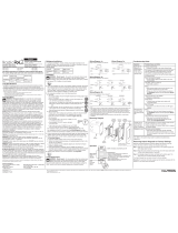
Multi-Unit Installations
When combining controls in a wallbox, remove all inner side sections prior to wiring (see below). Use pliers to
bend side section up and down until it breaks off. Repeat for each side section to be removed. Reduction of
dimmer capacity is also required. Refer to chart below for maximum dimmer capacity.
Remove all inner
side sections.
Do not remove
outer side sections.
(shaded)
Step 7 Turn power ON.
Step 6 Mount and align dimmer. Replace wallplate.
Step 5 Wire the dimmer.
• Connect the bare copper or green
ground wire to the green ground screw
on the dimmer (see Important Note 3).
• Connect one of the insulated wires
removed from the switch to either of
the screws (or backwire holes) on the
dimmer.
• Connect the other insulated wire
removed from the switch to the other
screw (or backwire hole) on the dimmer
Step 4 Prepare wires. Trim or strip wallbox wires to the length indicated by the
strip gauge on the back of the dimmer. Use the same procedure to wire
your new dimmer as was used with the old switch (see Step 3 and below).
Step 3 Disconnect switch wires.
Step 2 Remove switch mounting screws. Pull switch from wall.
Step 1 WARNING: Turn power OFF at circuit breaker or remove fuse.
Important Note: Your wall switch may have two wires attached to the same screw
(see illustrations below for examples). Tape these two wires together before disconnecting.
When wiring, connect wires to new dimmer the same way they were connected to
the switch.
One wire in the back-
wired hole and one to
the screw.
One continuous wire
to the screw.
Live
120 V~
60 Hz
Ground
Dimmer
Neutral
Light
English
Incandescent
Single-Pole: AY-600P, TG-600P
Rated at: 120 V 60 Hz 600 W
Magnetic Low-Voltage
Single-Pole: AYLV-600P
Rated at: 120 V 60 Hz 600 VA/450 W
Single-Pole Preset Dimmer
030-1273
030-1273
Screw Terminals:
Turn screws counterclockwise to loosen.
*Note: The maximum lamp wattage is determined by the efficiency of the transformer, with 70–85% as typical. For actual transformer
efficiency, contact either the fixture or transformer manufacturer. The total VA rating of the transformer(s) shall not exceed the VA rating
of the dimmer.
Turn screws
counterclockwise
to loosen.
?
Technical Assistance
If you have questions concerning the installation or operation of this product, call the
Lutron Technical Support
Center
. Please provide exact model number when calling.
U.S.A., Canada, and the Caribbean (24 hrs/7days)
1.800.523.9466
México +1.888.235.2910
Other countries 8am – 8pm ET
+1.610.282.3800
Fax +1.610.282.6311
http://www.lutron.com
WARNING: Shock Hazard. May result in
serious injury or death. Turn of power at
circuit breaker before installing the unit.
/