Champion Power Equipment 100742 Operating instructions

Type
Operating instructions
OPERATOR'S MANUAL
MODEL #100742
2 IN. (5 CM) SEMI-TRASH PUMP
Made in China - REV 20200520 Champion Power Equipment, Inc., Santa Fe Springs, CA USA
or visit championpowerequipment.com
READ AND SAVE THIS MANUAL. This manual contains important safety precautions which should be read and understood before operating the product. Failure to
do so could result in serious injury. This manual should remain with the product.
Specifications, descriptions and illustrations in this manual are as accurate as known at the time of publication, but are subject to change without notice.
REGISTER YOUR PRODUCT ONLINE
at championpowerequipment.com
2
100742 - 2 IN. (5 CM) SEMI-TRASH PUMP TABLE OF CONTENTS
TABLE OF CONTENTS
Introduction ................................................... 3
Safety Definitions .......................................... 3
Important Safety Instructions ....................... 4
Fuel Safety .........................................................6
Safety and Dataplate Labels .......................................7
Safety Symbols .....................................................8
Operation Symbols ............................................... 10
Quickstart Label Symbols........................................ 10
Controls and Features ................................. 11
Parts Included .................................................... 12
Assembly ..................................................... 13
Remove the Water Pump from the Shipping Carton ............ 13
Install Wheels and Support Legs ................................ 13
Add Engine Oil .................................................... 13
Add Fuel .......................................................... 14
Operation ..................................................... 15
Water Pump Location ............................................ 15
Connecting a Hose Kit ........................................... 16
Priming the Pump ................................................ 20
Before Starting the Engine ....................................... 21
Starting the Engine ............................................... 21
Stopping the Engine .............................................. 22
Operation at High Altitude ....................................... 22
Maintenance ................................................ 23
Cleaning the Water Pump ........................................ 23
Changing the Engine Oil ......................................... 23
Cleaning and Adjusting the Spark Plug(s) ....................... 24
Cleaning the Air Filter ............................................ 24
Cleaning the Spark Arrestor ..................................... 24
Adjusting the Governor ........................................... 25
Maintenance Schedule ........................................... 25
Storage ........................................................ 25
Water Pump Storage ............................................. 25
Short Term Engine Storage (Up to 30 Days) .................... 25
Mid Term Engine Storage ( 30 Days – 1 year) .................. 25
Long Term Storage ............................................... 26
Specifications .............................................. 27
Water Pump Specifications ...................................... 27
Engine Specifications ............................................ 27
Engine Oil Specifications ......................................... 27
Fuel Specifications ............................................... 27
Spark Plug Specifications ........................................ 27
Valve Specifications .............................................. 27
Important Message About Temperature......................... 27
Parts Diagram - Frame and Engine ............................. 28
Parts List ......................................................... 29
Engine Parts Diagram ............................................ 31
Engine Parts List ................................................. 32
Troubleshooting ........................................... 34
3
100742 - 2 IN. (5 CM) SEMI-TRASH PUMP INTRODUCTION
INTRODUCTION
Congratulations on your purchase of a Champion Power Equipment
(CPE) product. CPE designs, builds, and supports all of our
products to strict specifications and guidelines. With proper
product knowledge, safe use, and regular maintenance, this
product should bring years of satisfying service.
Every effort has been made to ensure the accuracy and
completeness of the information in this manual at the time of
publication, and we reserve the right to change, alter and/or
improve the product and this document at any time without prior
notice.
Since CPE highly values how our products are designed,
manufactured, operated and are serviced, and also highly value
your safety and the safety of others, we would like you to take the
time to review this product manual and other product materials
thoroughly and be fully aware and knowledgeable of the assembly,
operation, dangers and maintenance of the product before use.
Fully familiarize yourself, and make sure others who plan on
operating the product fully familiarize themselves too, with the
proper safety and operation procedures before each use. Please
always exercise common sense and always err on the side
of caution when operating the product to ensure no accident,
property damage, or injury occurs. We want you to continue to use
and be satisfied with your CPE product for years to come.
When contacting CPE about parts and/or service, you will need to
supply the complete model and serial numbers of your product.
Transcribe the information found on your product’s nameplate
label to the table below
CPE TECHNICAL SUPPORT TEAM
1-877-338-0999
MODEL NUMBER
100742
SERIAL NUMBER
DATE OF PURCHASE
PURCHASE LOCATION
SAFETY DEFINITIONS
The purpose of safety symbols is to attract your attention to
possible dangers. The safety symbols, and their explanations,
deserve your careful attention and understanding. The safety
warnings do not by themselves eliminate any danger.
The instructions or warnings they give are not substitutes for
proper accident prevention measures.
DANGER
DANGER indicates a hazardous situation which, if not avoided,
will result in death or serious injury.
WARNING
WARNING indicates a hazardous situation which, if not
avoided, could result in death or serious injury.
CAUTION
CAUTION indicates a hazardous situation which, if not avoided,
could result in minor or moderate injury.
NOTICE
NOTICE indicates information considered important, but not
hazard-related (e.g., messages relating to property damaged).
4
100742 - 2 IN. (5 CM) SEMI-TRASH PUMP IMPORTANT SAFETY INSTRUCTIONS
IMPORTANT SAFETY INSTRUCTIONS
WARNING
Cancer and Reproductive Harm – www.P65Warnings.ca.gov
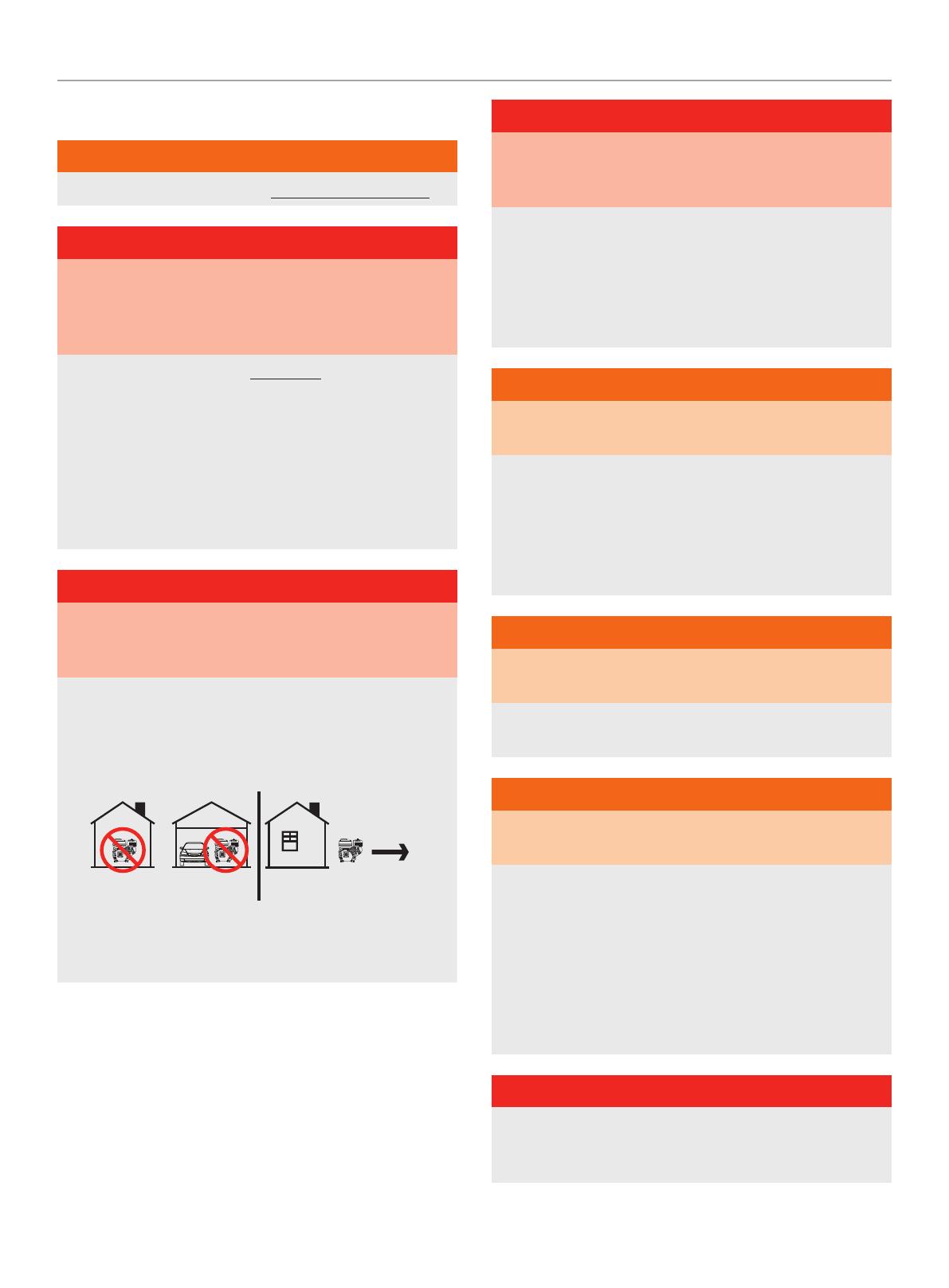
DANGER
Water pump engine exhaust contains carbon monoxide,
a colorless, odorless, poison gas. Breathing carbon monoxide
will cause nausea, dizziness, fainting or death.
If you start to feel dizzy or weak, get to fresh air immediately.
OPERATE THE WATER PUMP OUTDOORS ONLY IN A WELL
VENTILATED AREA AND POINT EXHAUST AWAY.
DO NOT operate the water pump inside any building, including
garages, basements, crawlspaces and sheds, enclosure
or compartment, including the storage compartment of a
recreational vehicle.
DO NOT allow exhaust fumes to enter a confined area through
windows, doors, vents or other openings.
DANGER
Using an engine indoors CAN KILL YOU IN MINUTES. Engine
exhaust contains carbon monoxide. This is a poison you cannot
see or smell.
NEVER use inside a home or garage, EVEN IF doors and
windows are open.
ONLY use OUTSIDE and far away from windows, doors,
and vents.
Install battery-operated carbon monoxide alarms or plug-in
carbon monoxide alarms with battery back-up according to the
manufacturer’s instructions.
DANGER
Rotating parts can entangle hands, feet, hair, clothing and/or
accessories. Traumatic amputation or severe laceration can
result.
Keep hands and feet away from rotating parts.
Tie up long hair and remove jewelry.
Operate equipment with guards in place.
DO NOT wear loose-fitting clothing, dangling drawstrings or
items that could become caught.
WARNING
Spark from removed spark plug wire can result in fire or
electrical shock.
When servicing the water pump:
Disconnect the spark plug wire and place it where it cannot
contact the plug or any other metal object.
DO NOT check for spark with the plug removed.
Use only approved spark plug testers.
WARNING
Contact with electrical power source can cause electric shock
or burn.
NEVER spray in the direction of or near a power source/
electrical outlet.
WARNING
Running engines produce heat. Severe burns can occur on
contact. Combustible material can catch fire on contact.
DO NOT touch hot surfaces.
Avoid contact with hot exhaust gases.
Allow equipment to cool before touching.
Maintain at least 3 ft. (91.4 cm) of clearance on all sides to
ensure adequate cooling.
Maintain at least 5 ft. (1.5 m) of clearance from combustible
materials.
DANGER
DO NOT pump gasoline, fuel, fuel-oil mixtures, detergents,
acids, chemicals, beverages, pesticides, fertilizers or any other
flammable liquid or corrosive.
5
100742 - 2 IN. (5 CM) SEMI-TRASH PUMP IMPORTANT SAFETY INSTRUCTIONS
WARNING
DO NOT immerse the water pump in water.
DANGER
The water pump develops powerful force.
DO NOT move the water pump when it is in use.
DO NOT use hoses or connectors that are worn, damaged or
frayed.
DO NOT allow children or unqualified persons to operate or
service the water pump.
DO NOT open top plug or drain plug.
WARNING
Rapid retraction of the starter cord will pull hand and arm
towards the engine faster than you can let go. Unintentional
startup can result in entanglement, traumatic amputation or
laceration. Broken bones, fractures, bruises or sprains could
result.
When starting engine, pull the starter cord slowly until
resistance is felt and then pull rapidly to avoid kickback.
WARNING
DO NOT pump salt, sludge, sewer, sea, or any other type of
water containing solid material.
CAUTION
Exceeding the pump specification for total head can damage
the pump and/or hose kits connected to it.
DO NOT modify the pump in any way. DO NOT attempt to
exceed the rated flow. Attempting to increase the rated flow
may damage the unit and/or shorten its life.
NOTICE
DO NOT run the pump dry.
Running the pump dry can destroy the pump seals and will
void the warranty. If the pump was running while dry, stop
the engine and allow it to cool thoroughly before filling the
chamber with water.
CAUTION
Improper treatment or use of the water pump can damage it,
shorten its life and void your warranty.
Use the water pump only for intended uses.
Operate only on level surfaces.
DO NOT expose water pump to excessive moisture, dust,
or dirt.
DO NOT allow any material to block the cooling slots.
DO NOT use the engine if:
Equipment sparks, smokes or emits flames
Equipment vibrates excessively
WARNING
Use of this water pump can create wet, slippery walking
surfaces.
Use only on a level surface.
Make sure there is proper drainage to dissipate water.
6
100742 - 2 IN. (5 CM) SEMI-TRASH PUMP IMPORTANT SAFETY INSTRUCTIONS
Fuel Safety
DANGER
GASOLINE AND GASOLINE VAPORS ARE HIGHLY
FLAMMABLE AND EXPLOSIVE.
Fire or explosion can cause severe burns or death.
Gasoline and gasoline vapors:
Gasoline is highly flammable and explosive.
Gasoline can cause a fire or explosion if ignited.
Gasoline is a liquid fuel but its vapors can ignite.
Gasoline is a skin irritant and needs to be cleaned up
immediately if spilled on skin or clothes.
Gasoline has a distinctive odor, this will help detect potential
leaks quickly.
In any petroleum gas fire, flames should not be extinguished
unless by doing so the fuel supply valve can be turned OFF.
This is because if a fire is extinguished and a supply of fuel is
not turned OFF, then an explosion hazard could be created.
Gasoline expands or contracts with ambient temperatures.
Never fill the gasoline tank to full capacity, as gasoline needs
room to expand if temperatures rise.
When adding or removing gasoline:
DO NOT light or smoke cigarettes.
Turn the engine off and let it cool for at least two minutes before
removing the gasoline cap. Loosen the cap slowly to relieve
pressure in the tank.
Only fill or drain gasoline outdoors in a well-ventilated area.
DO NOT pump gasoline directly into the engine at the gas station.
Use an approved container to transfer the fuel to the engine.
DO NOT overfill the gasoline tank.
Always keep gasoline away from sparks, open flames, pilot lights,
heat and other sources of ignition.
When starting the engine:
DO NOT attempt to start a damaged engine.
Make certain that the gasoline cap, air filter, spark plug, fuel lines
and exhaust system are properly in place.
Allow spilled gasoline to evaporate fully before attempting to start
the engine.
Make certain that the water pump is resting firmly on level ground.
When operating the water pump:
DO NOT move or tip the water pump during operation.
DO NOT tip the water pump or allow fuel or oil to spill.
When transporting or servicing the water pump:
Make certain that the fuel valve is in the OFF position, the gasoline
tank is empty.
Disconnect the spark plug wire.
When storing the water pump:
Store away from sparks, open flames, pilot lights, heat and other
sources of ignition.
Do not store water pump or gasoline near furnaces, water heaters,
or any other appliances that produce heat or have automatic
ignitions.
WARNING
NEVER use a gasoline container, gasoline tank, or any other
fuel item that is broken, cut, torn or damaged.
7
100742 - 2 IN. (5 CM) SEMI-TRASH PUMP IMPORTANT SAFETY INSTRUCTIONS
Side Side
Safety and Dataplate Labels
These labels warn you of potential hazards that can cause serious injury. Read them carefully.
If a label comes off or becomes hard to read, contact Technical Support Team for possible replacement.
LABEL DESCRIPTION
A
2012-L-OP-a
DaNGER PELIGRO DaNGER
2012-L-OP-a
K109 485 --- ---
ColorsLPN 2012-L-OP
Rev A
Size Spec’d by CPEC
Artwork Notes
2mm safe margin;
to be pr inted on w hite substrate
Revision Changes
---
This ar twork belongs to Champion Power Equipment. The contents are confidential and privileged and shall not be disclosed to or used by or for
outside parties without the explicit consent of Champion Power Equipment.
Safety Symbols/
CO Danger
B
UNLEADED FUEL ONLY. Minimum octane
rating of 87. Maximum 10% ethanol.
GASOLINA REGULAR SOLAMENTE.
87 octanos como mínimo. Máximo de
etanol de 10%.
ESSENCE SANS PLOMB
SEULEMENT. Indice d’octane
minimal de 87. Maximum
10 % d'éthanol.
2
2011-L-OP-a
K376 --- --- ---
ColorsLPN 2011- L- OP
Rev A
Size 38 x 3 8 mm
Artwork Notes
2mm safe margin;
to be pr inted on white su bstrate
Revision Changes
---
This ar twork belongs to Champion Power Equipment. The contents are confidential and privileged and shall not be disclosed to or used by or for
outside parties without the explicit consent of Champion Power Equipment.
Fuel
C
WaRNING
DO NOT TOUCH!
Exhaust gases, muffler
and engine components
are extremely HOT and
cause burns.
Operation of this equipment may create sparks that can start
fires around dry vegetation. A spark arrestor may be
required. The operator should contact local fire agencies for
laws and regulations relating to fire p revention requirements.
If installed, clean every 100 hour s or every season.
aDVERTENCIa
¡NO TOCAR! Los gases de
escape, el silenciador y los
compnonentes del motor están
extremadamente CALIEN TES y
causan quemaduras.
La operación de este equipo puede p roducir chispas que pueden provocar
incendios alrededor de la vegetación seca. Un supresor de chispas puede que
sea necesario. El operador debe comunicarse con las agencias locales de
bomberos para las leyes y reglamentos relativos a los requisitos de prevención
de incendios . Si está instalado, limp ie cada 100 horas o cada tem porada.
aVERTISSEmENT
NE PAS TOUCHER! Les ga z
d’échappement, le silencieux
et les pièces du moteur sont
extrêmeme nt CHAUDS et
peuvent causer des brûlures.
Cet équipem ent peut créer des étince lles et provoquer un incend ie dans la
végétation sèche. Un pare-ét incelles peut être requis. L’utilisateur doit
communiquer avec le service d’incendie local pour connaître les lois et
les règlements en matière de prévention des incendies. Si elle est
installée, nettoyez la génératrice toutes les 100 heures ou chaque saison.
1035-L-SF-C
ColorsLPN 1035-L-SF
Rev C
Size 369 x 2 6 mm
Artwork Notes
3mm corner radius; 2mm safe margin
Revision Changes
C: updated some FR translation words.
This artw ork belongs to Champio n Power Equipment. Th e contents are confi dential and privileg ed and shall not be disclo sed to or used by or for
outside par ties without th e explicit consent o f Champion Power Equip ment.
K485 152 --- ---
Hot Surface
D
CHAMPION POWER EQUIPMENT, INC.
12039 SMITH AVENUE
SANTA FE SPRINGS, CA 90670
USA / É.-U.
1-877-338-0999
WWW.CHAMPIONPOWEREQUIPMENT.COM
MADE IN CHINA / FABRIQUÉ EN CHINE
MODEL
MODÈLE
MANUFACTURE DATE
DATE DE FABRICATION
FLOW (GPM / LPM)
DÉBIT (GPM / LPM)
INLET DIAMETER
DIAMÈTRE D'ENTRÉE
2172-L-PR-a
100742 158 / 598
2 IN.
5 CM
SERIAL NO. / N° DE SÉRIE
XXXX XXXXXXXXXXXX
K--- --- --- ---
ColorsLPN 2172-L-PR
Rev A
Size 123 x 40 mm
Artwork Notes
3mm corner radius; 2mm safe margin
Revision Changes
---
This ar twork belongs to Champion Power Equipment. The contents are confidential and privileged and shall not be disclosed to or used by or for
outside parties without the explicit consent of Champion Power Equipment.
Dataplate
C
D
B
A
8
100742 - 2 IN. (5 CM) SEMI-TRASH PUMP IMPORTANT SAFETY INSTRUCTIONS
Safety Symbols
Some of the following symbols may be used on this product. Please study them and learn their meaning. Proper interpretation of these
symbols will allow you to more safely operate the product.
SYMBOL MEANING
Read Operators Manual. To reduce the risk of injury, user must read and understand operator’s
manual before using this product.
Eye and Ear Protection. Always wear safety goggles or safety glasses with side shields, and as
necessary a full face-shield as well as full ear protection when operating this product.
Footwear. Always wear safety shoes or heavy boots when operating the machine.
Gloves. Always wear nonslip, heavy-duty protective gloves when operating this product.
Safety Alert. Precautions that involve your safety.
Risk of Fire. Fuel and its vapors are extremely flammable and explosive. Fire can cause severe
burns or death. Do not add fuel while the product is operating or still hot.
Hot Surface. To reduce the risk of injury or damage, avoid contact with any hot surface
Open Flame alert. Fuel and its vapors are extremely flammable and explosive. Keep fuel away
from smoking, open flames, sparks, pilot lights, heat, and other ignition sources.
9
100742 - 2 IN. (5 CM) SEMI-TRASH PUMP IMPORTANT SAFETY INSTRUCTIONS
SYMBOL MEANING
Toxic Fumes. The engine exhaust from this product contains chemicals known to the state of
California to cause cancer and birth defects and other reproductive harm.
Risk of Asphyxiation. This engine emits carbon monoxide, an odorless, colorless poison gas.
Breathing carbon monoxide can cause nausea, fainting or death. Use only in a well ventilated
area.
Clearance. Keep all objects including others at least 10 feet (3m) from this machine.
Only one person should operate the water pump and load the logs
10
100742 - 2 IN. (5 CM) SEMI-TRASH PUMP IMPORTANT SAFETY INSTRUCTIONS
Operation Symbols
Some of the following symbols may be used on this product. Please study them and learn their meaning. Proper interpretation of these
symbols will allow you to more safely operate the product.
Quickstart Label Symbols
Some of the following symbols may be used on this product. Please study them and learn their meaning. Proper interpretation of these
symbols will allow you to more safely operate the product.
Starting the Engine
DANGER
Move water pump outside and far away from windows,
doors and intake ventilation covers.
1. Check oil level. Recommended oil is 10W-30.
2. Check fuel level.
3. Connect inlet and outlet hoses
4. Connect inlet filter
5. Prime the water pump
6. Move the fuel valve to the “ON” position.
7. Move the choke lever to the “CHOKE” position by pulling out.
8. Move throttle to “FAST” position.
9. Press engine switch to “ON” position.
SYMBOL MEANING
Choke. Pull choke knob to “CHOKE”
position.
Run. Push choke knob to “RUN”
position.
Fuel/Gasoline Valve On/Off
Fuel Gauge: Full
Fuel Gauge: Empty
SYMBOL MEANING
On
Stop or Off
Throttle Lever - Fast
Throttle Lever - Slow
10. Pull the starter cord slowly until resistance is felt and then
pull rapidly.
11. As engine warms up, move the choke to “RUN” by pushing in
and adjust the throttle as needed
Stopping
1. Move the fuel valve to the “OFF” position.
2. Press the engine switch to the “OFF” position.
3. Disconnect inlet and outlet hoses for storage.
4. Remove drain plug (bottom) before storage.
2174-L-OP-a
8
1
10W-30
2
6 73 54
1 42 3119 10
K376 485 152 300 186CG1CG7
ColorsLPN 2174 -L-OP
Rev A
Size Spec’d by CPEC
Artwork Notes
3mm corner radius; 2mm safe margin; to be printed
on white substrate.
Revision Changes
---
This ar twork belongs to Champion Power Equipment. The contents are confidential and privileged and shall not be disclosed to or used by or for
outside parties without the explicit consent of Champion Power Equipment.
11
100742 - 2 IN. (5 CM) SEMI-TRASH PUMP CONTROLS AND FEATURES
CONTROLS AND FEATURES
Read this operators manual before operating your water pump. Familiarize yourself with the location and function of the controls and
features. Save this manual for future reference.
1. Gasoline Tank Cap
2. Gasoline Tank
3. Air Filter
4. Support Leg
5. Transport Handle
6. Throttle
7. Fuel Valve
8. Recoil Handle
9. Oil Drain Bolt (on each side)
10. Engine Oil Fill Cap/Dipstick
11. Wheels
12. Engine Switch
13. Choke
14. Fuel Gauge
15. Drain Plug (bottom)
16. Inlet
17. Muffler
18. Outlet
19. Priming Cap (top)
141
2
15
18
19
16
5
11
8 9 10
3
4
12
13 17
6
7
12
100742 - 2 IN. (5 CM) SEMI-TRASH PUMP CONTROLS AND FEATURES
Parts Included
Assembly Parts
Part Part Qty. Hardware Needed Hardware Qty. Tool Needed
Wheels 2
Wheel cap 2
N/AR-clip 2
Roll pin Ø16×96 2
Support Leg 2Bolt M6×40 41× 8mm wrench or socket
Flange lock nut M6 41× 10mm wrench or socket
Discharge hose (blue) 1
Outlet hose adapter 1
N/AOutlet hose fitting 1
Gasket 1
Silver colored hose clamp
2” 52-55mm 11× 10mm wrench or socket
Suction hose (green)
1Cam lock coupler (2 parts,
coupler and fitting) 1N/A
1
Filter (2 parts) 1
Gold colored hose clamp
2” 54-57 mm 31× 10mm wrench or socket
Accessory Bag 1N/A
Engine oil funnel 1N/A
Teflon® tape 1N/A
Parts Not Included
Engine Oil (10W-30)
13
100742 - 2 IN. (5 CM) SEMI-TRASH PUMP ASSEMBLY
ASSEMBLY
Your water pump requires some assembly. This unit ships from
the factory without oil. It must be properly serviced with fuel and
oil before operation. For questions regarding the assembly of your
water pump, call our help line at 1-877-338-0999. Please have
your serial number and model number available.
Remove the Water Pump from the Shipping
Carton
1. Set the shipping carton on a solid, flat surface.
2. Remove all contents from the carton except the water pump.
3. Carefully cut each corner of the box from top to bottom.
Install Wheels and Support Legs
Wheels
1. Before adding fuel and oil, carefully pivot the water pump up
and forward so that it rests engine side down. Place a piece
of cardboard from the packaging or moving blanket on the
ground before tipping forward.
2. Slide the roll pin through the wheel from the outside.
3. Slide the roll pin through the mount point on the frame.
4. Secure with the R-clip.
5. Repeat to attach the second wheel.
6. Add wheel caps to protect the roll pins.
Support Legs
1. Attach the supports legs to the water pump frame with
(2) M6 × 40 flange bolts and (2) M6 flange lock nuts per leg.
Tighten to 7.4±1.5 lbf-ft (10±2 Nm).
2. Repeat to attach the second leg.
3. Slowly tip the water pump back down so that it rests on the
support legs.
Add Engine Oil
CAUTION
DO NOT attempt to crank or start the engine before it has been
properly filled with the recommended type and amount of oil.
Damage to the engine as a result of failure to follow these
instructions will void your warranty.
NOTICE
The engine rotor has a sealed, pre-lubricated ball bearing that
requires no additional lubrication for the life of the bearing.
NOTICE
The recommended oil type is 10W-30 automotive oil.
If running engine in extreme temperatures, refer to the
following chart for recommended oil type.
1. Place the water pump on a flat, level surface.
2. Remove oil fill cap/dipstick to add oil.
3. Using a funnel, add up to 16.9 fl. oz (500 ml) of oil and
replace oil fill cap/dipstick. DO NOT OVERFILL.
14
100742 - 2 IN. (5 CM) SEMI-TRASH PUMP ASSEMBLY
4. Check engine oil level before every use and add as needed.
MAX
OIL DIP STICK
NOTICE
Once oil has been added, a visual check should show oil about
1-2 threads from running out of the fill hole.
If using the dipstick to check oil level, DO NOT screw in the
dipstick while checking.
NOTICE
Check oil often during the break-in period. Refer to the
Maintenance section for recommended service intervals.
CAUTION
The engine is equipped with a low oil shut-off and will stop
when the oil level in the crankcase falls below the threshold
level.
NOTICE
The first 5 hours of run time is the break-in period for the
engine. During the break in period, it is recommended to use
standard automotive, non-synthetic blended oils. After the
break-in period, synthetic oil can be used but is not required.
Adjusting throttle setting will increase/ decrease engine speed
helping to seat piston rings. Avoid bogging or lugging the
engine down and avoid prolonged running at constant RPM.
After the 5-hour break-in period, change the oil.
NOTICE
Synthetic oil may be used after the 5 hour initial break-in
period. Using synthetic oil does not decrease the recommended
oil change interval. Full synthetic 5W-30 oil will aid in starting
in cold ambient < 41º F (5º C).
-20 020 40 60
Ambient temperature
Recommended Engine Oil Type
80 100 120
-28.9
°F
°C -17.8 -6.7 4.4 15.6 26.7 37.8 48.9
10W-30
5W-30 Synthetic
10W-405W-30
NOTICE
Weather will affect engine oil and engine performance. Change
the type of engine oil used based on weather conditions to suit
the engine needs.
Add Fuel
Use clean, fresh, regular unleaded gasoline with a minimum
octane rating of 87 and an ethanol content of less than 10% by
volume. ybc
DO NOT mix oil with gasoline.
1. Place the water pump on a flat, level surface.
2. Remove the gasoline cap.
3. Slowly add gasoline to the tank. DO NOT OVERFILL. Gasoline
can expand after filling. A minimum of ¼ in. (6.4 mm) of
space left in the tank is required for gasoline expansion,
although more than ¼ in. (6.4 mm) is recommended. Gasoline
can be forced out of the tank as a result of expansion if
overfilled, and can affect the stable running condition of the
water pump. The approximate fuel level is shown on the fuel
gauge on top of the fuel tank.
15
100742 - 2 IN. (5 CM) SEMI-TRASH PUMP OPERATION
EMPTY FULL
4. Screw on the gasoline cap and wipe away any spilled fuel.
CAUTION
Use regular unleaded gasoline with a minimum octane rating
of 87 and an ethanol content of less than 10% by volume.
DO NOT light cigarettes or smoke when filling the tank.
DO NOT mix oil and gasoline.
Fill tank to approximately ¼ in. (6.4 mm) below the top of the
tank to allow for gasoline expansion.
DO NOT pump gasoline directly into the water pump at the
pump. Use an approved container to transfer the gasoline to
the water pump.
DO NOT fill tank indoors.
DO NOT fill tank when the engine is running or hot.
DO NOT overfill the tank.
WARNING
Pouring gasoline too fast through the fuel screen may result in
blow back of gasoline at the operator while filling.
NOTICE
Our engines work well with 10% or less ethanol blend
gasoline. When using ethanol-gasoline blends there are some
issues worth noting:
Ethanol-gasoline blends can absorb more water than
gasoline alone.
These blends can eventually separate, leaving water or a
watery goo in the tank, fuel valve and carburetor.
With gravity-fed supplies, the compromised gasoline can
be drawn into the carburetor and cause damage to the
engine and/or potential hazards.
There are only a few suppliers of fuel stabilizer that are
formulated to work with ethanol-gasoline blends.
Any damages or hazards caused by using improper
gasoline, improperly stored gasoline, and/or improperly
formulated stabilizers, are not covered by manufacturer’s
warranty.
It is advisable to always shut off the gasoline supply, run the
engine to starvation and drain the tank when the equipment is
not in use for more than 30 days.
OPERATION
Water Pump Location
DANGER
Water pump engine exhaust contains carbon monoxide,
a colorless, odorless, poison gas. Breathing carbon monoxide
will cause nausea, dizziness, fainting or death.
If you start to feel dizzy or weak, get to fresh air immediately.
OPERATE THE WATER PUMP OUTDOORS ONLY IN A WELL
VENTILATED AREA AND POINT EXHAUST AWAY.
DO NOT operate the water pump inside any building, including
garages, basements, crawlspaces and sheds, enclosure
or compartment, including the storage compartment of a
recreational vehicle.
DO NOT allow exhaust fumes to enter a confined area through
windows, doors, vents or other openings.
16
100742 - 2 IN. (5 CM) SEMI-TRASH PUMP OPERATION
DANGER
Using an engine indoors CAN KILL YOU IN MINUTES. Engine
exhaust contains carbon monoxide. This is a poison you cannot
see or smell.
NEVER use inside a home or garage, EVEN IF doors and
windows are open.
ONLY use OUTSIDE and far away from windows, doors,
and vents.
Install battery-operated carbon monoxide alarms or plug-in
carbon monoxide alarms with battery back-up according to the
manufacturer’s instructions.
WARNING
Running engines produce heat. Severe burns can occur on
contact. Combustible material can catch fire on contact.
DO NOT touch hot surfaces.
Avoid contact with hot exhaust gases.
Allow equipment to cool before touching.
Maintain at least 3 ft. (91.4 cm) of clearance on all sides to
ensure adequate cooling.
Maintain at least 5 ft. (1.5 m) of clearance from combustible
materials.
Place the water pump on a flat, level surface. The pump should
be placed close to the water level to ensure maximum pump
performance.
Pump output will be affected by the type, length, and size of the
suction and discharge hoses. The pumping height, also known as
the total head, is the distance from the water level to the point of
discharge. As this distance increases, pump output decreases.
The discharge capacity is greater than the suction capacity.
Therefore, it is important that the suction head is less than the
discharge head. The time required to draw water from the source
to the pump (self-priming time) can be decreased by minimizing
the suction head.
Total Head
Suction Head
Discharge Head
Connecting a Hose Kit
NOTICE
Both the inlet and outlet ports are 2 in. (5 cm) NPT. Please
ensure the connectors to the suction and discharge hose are 2
in. (5 cm) NPT threaded.
Connect the Discharge Hose (Blue)
1. Locate (1) of the following: outlet hose adapter (C), gasket (A),
and outlet hose fitting (B) and align for assembly.
A
B
C
2. Thread the assembled connector to the outlet fitting (top of
pump). Locate the blue “outlet” label on the pump.
NOTICE
Make sure the gasket is seated inside before threading the
adapter on.
17
100742 - 2 IN. (5 CM) SEMI-TRASH PUMP OPERATION
3. Locate and slide the silver colored hose clamp (marked 52-
55) over the blue outlet hose.
4. Slide the blue discharge hose over the outlet hose fitting.
NOTICE
You may use a small amount of dish soap on the outlet hose
fitting to help ease the outlet hose on the fitting. Work the
soap around the fitting with your finger. Then work the blue
hose on the outlet, by twisting and turning until it’s fully
seated.
5. Slide the hose clamp in place about midway on the outlet
hose adapter as shown. Tighten to 7.4±1.5 lbf-ft (10±2 Nm)
with a 10mm wrench. The hose clamp should be placed
behind the outlet adapter barbs on the smooth part of the
adapter.
Connect the Suction Hose (Green) and Suction Filter
1. Locate the following: cam lock coupler (coupler and fitting
together) (A), 54-57 marked hose clamps (B), Teflon® tape
(C), green suction hose (D) and align for assembly.
A
B
C
D
2. Cut ties and uncoil the green hose and use some weight to
help straighten the hose out. Best to do this on a warmer day
in the sun.
18
100742 - 2 IN. (5 CM) SEMI-TRASH PUMP OPERATION
3. Separate the cam lock coupler and fitting. Align the green
hose to the coupler and mark the locations of the ribs on the
fitting.
4. Mark the second rib on the coupler on the hose.
5. Lay the green hose side by side and place the clamp marked
54-57 in their approximate location.
6. Slide the clamps back and start to assemble the green hose
to cam lock coupler.
7. Insert the threaded or quick coupler in the green rigid suction
hose until properly seated.
NOTICE
You may use a small amount of dish soap on the cam lock
coupler to help ease the green hose on the fitting. Work
the soap around the coupler with your finger. Then work the
green hose on the fitting, by twisting and turning until it’s fully
seated.
8. Slide the clamps marked 54-57 over cam lock coupler just
past the marks you made on the hose earlier.
9. Rotate and align the clamp bolts so you have clearance for
the cam levers to lock in place later.
19
100742 - 2 IN. (5 CM) SEMI-TRASH PUMP OPERATION
10. Tighten each clamp to 7.4±1.5 lbf-ft (12 Nm) with a 10mm
wrench. If you do not have a torque wrench, hand tight then
¼ turn past full tight.
11. Test connection is tight by twisting coupler in the hose to
make sure it doesn’t turn. If coupling turns, then tighten
clamps further until coupling won’t turn.
12. Wrap the green inlet clockwise with the Teflon® tape provided
with 4 complete wraps.
13. Thread the fitting over the tape and hand tighten. If you have
channel locks large enough, you can give it a ¼ turn past
hand tight.
14. Attach the cam lock coupler to the fitting.
15. Lock in place with the cam levers.
NOTICE
If the cam levers do not clamp down completely, rotate and
align the clamp bolts so you have clearance for the cam levers
to lock. See step 9 earlier.
16. Locate the following: filter (E) and 54-57 marked hose
clamp (F).
E
F
17. Snap the filter pieces together.
20
100742 - 2 IN. (5 CM) SEMI-TRASH PUMP OPERATION
18. Place the clamp marked 54-57 on the other end of the green
hose. Attach the strainer to the green suction hose.
NOTICE
You may use a small amount of dish soap on the filter to help
ease the green hose on the filter. Work the soap around the
filter with your finger. Then work the green hose on the filter,
by twisting and turning until it’s fully seated.
19. Slide the clamp just before the end of the green hose.
20. Tighten the clamp to 7.4±1.5 lbf-ft (10±2 Nm) with a 10mm
wrench. If you do not have a torque wrench, hand tight then
¼ turn past full tight.
21. You should have everything connected.
Priming the Pump
NOTICE
DO NOT run the pump dry.
Running the pump dry can destroy the pump seals and will void
the warranty. If the pump was running while dry, stop the engine
and allow it to cool thoroughly before filling the chamber with
water.
NOTICE
Ensure the priming plug is secure before pump operation, if not
secure the priming plug could be ejected and water or other
liquids could be pumped through the top of the outlet flange.
1. Remove the priming cap (top) and fill pump body to the very
top of outlet flange with water. Reinstall the priming plug. DO
NOT over tighten.
2. As the engine starts up, this will start the draw of liquid into
the pump. Located within the pump assembly is the one-
way valve. As you prime the pump housing this one-way flap
valve shuts off the opening to the suction hose. The priming
process is only required when the pump housing is not full of
water.
  • Page 1 1
  • Page 2 2
  • Page 3 3
  • Page 4 4
  • Page 5 5
  • Page 6 6
  • Page 7 7
  • Page 8 8
  • Page 9 9
  • Page 10 10
  • Page 11 11
  • Page 12 12
  • Page 13 13
  • Page 14 14
  • Page 15 15
  • Page 16 16
  • Page 17 17
  • Page 18 18
  • Page 19 19
  • Page 20 20
  • Page 21 21
  • Page 22 22
  • Page 23 23
  • Page 24 24
  • Page 25 25
  • Page 26 26
  • Page 27 27
  • Page 28 28
  • Page 29 29
  • Page 30 30
  • Page 31 31
  • Page 32 32
  • Page 33 33
  • Page 34 34
  • Page 35 35
  • Page 36 36
  • Page 37 37
  • Page 38 38
  • Page 39 39

Champion Power Equipment 100742 Operating instructions

Type
Operating instructions

Ask a question and I''ll find the answer in the document

Finding information in a document is now easier with AI