Page is loading ...

Downloaded from: http://www.guardianalarms.net

Ta ble of Con tents
Stan dard Fea tures of the ACE 7500 ......................... 2
Im por tant In for ma tion ................................ 3
Re quired In stal la tion Tools ............................. 3
Sys tem Com po nents ................................. 3
Wir ing Dia gram - 12- pin Connector ......................... 4
Wir ing Dia gram - 24- pin Con nec tor ......................... 5
Con trol Unit and Ex tended Range Receiver ..................... 5
Starter and Ig ni tion Con nec tions .......................... 6
Im mo bi li za tion Cir cuits ...................................6
Starter Con nec tion ..................................... 6
Heater/Air Con di tioner Con nec tion ............................. 6
Ac ces sory Line Con nec tion ................................. 7
Sec on dary Ig ni tion or Heater/AC Wire............................ 7
LED Status In di ca tor................................. 7
Plain View 2 Coded Valet/Programming Switch ................... 7
Door Trig ger/In te rior Light Sup ply.......................... 7
Door Locks..................................... 7-8
Park ing Lights....................................9
Fac tory Theft De ter rent By pass........................... 10
Re verse Lights ...................................10
Brake Lights..................................... 10
Man ual Trans mis sion................................10
Die sel En gine....................................10
RPM Moni tor ing...................................11
Trunk Trig ger....................................11
Re motely Ad just able Dual- Zone Piezo Sen sor ................... 12
Glass Tam per ing Sen sor .............................. 12
Aux il iary A with Se lecta ble Out put Type and AutoAc ti va tion ........... 12
Euro pean Ve hi cle Win dow/Sun roof All- Close........................ 12
Hood Trig ger.................................... 12
High Out put In sig nia Si ren............................. 13
Fi nal Wir ing Con nec tions..............................13
Smart Powe rUp 2 ..................................13
Man da tory RPM Pro gram ming........................... 13
De layed Cour tesy Lights ..............................13
Re mote Con trol Op era tion .............................14
Com pan ion & Mas ter Re mote Con trols ........................... 14
Sen sor Adjustment ................................. 15
Eight- Event To tal Re call...............................15
Pro gram ma ble Fea tures..............................15
Us ing Cliff Net Wiz ard PRO ................................15
Pro gram ming the User- Selectable Fea tures ......................... 16
User- Programmable Fea tures ............................... 16
In staller Pro gram ma ble Fea tures.............................. 17
Sys tem Check list and Trou ble shoot ing ..................... 18-22
1

Stan dard Fea tures of the ACE 7500
2
o Lifetime Warranty
o His & Hers Remote Controls
o ACG™ 2 (Anti-CodeGrabbing™)
o Extended Range Receiver
o Remote Engine Starting with
AutoStart
o Works with Automatic or Manual
Transmissions
o Works with Diesel or Gas Engines
oAudible Low-Battery Warning
o Built-In Two-Point Immobilizer™
o Patented PlainView 2 Coded Valet
Mode™
oRemotely Adjustable Dual-Zone
Piezo Sensor
o Glass Tampering Sensor
o FACT: False Alarm Control and Test
o Enhanced User-Selectable
AutoArming
o User-Selectable Remote Valet Mode
o BlackJax Anti-Carjacking Subsystem
o Optional DataPort™ Interface and
CliffNet Wizard™ Software
o Remote Panic with Smart
Locking/Unlocking
o Remote Door Locking/Unlocking
o User-Selectable AutoLock
o Remote Keyless Entry & Accessory
Activation in Valet Mode
o Integrated Electronic Timer
o Turbo Timer Output
o DataPort Accessory Interface
o High-Output Insignia Siren
o Eight-Event TotalRecall™
o Prewired LED, Sensor, Extended
Range Receiver and PlainView 2
Switch Connectors
o Dual-Mode “Chirp” Silencing
o Remote Siren Silencing
o Smart Remote Trunk Release
o Built-In Dual Parking Light Flasher
with Onboard Relay
o Remote-Controlled Courtesy
Lighting
o Patented Smart AutoTesting™
o Patented Malfunction AutoBypass™
with AutoReMonitoring
o Patented Smart Prior Intrusion
Attempt Alert
o Remote Control Code Learning
and MultiRemote Recognition
o Clear All Remotes
o Multiple-Car Control
o LED Status Indicator with
Automatic Battery-Saving Mode
o Multiple Sensor/Trigger Inputs
oPatented SmartPowerUp™ 2
o Advanced CMOS Microcomputer
o One Accessory Channel with
Selectable Output Type
o Preloomed Wiring
o Full-Time SecureAccess™
Programming
o AutoActivation of Auxiliary
Output for Window All-Close on
European Vehicles
o Installer-Selectable Door
Ajar/Delayed Courtesy Lights

Im por tant In for ma tion
1.DO NOT dis con nect the bat tery ca bles! Make bat tery con nec tions by re mov ing the lug
nuts from the bat tery clamps with out de tach ing the clamp it self.
2. Turn off the in te rior lights or re move the dome light fuse bef ore start ing the in stal la tion ;
oth er wise, leav ing the door(s) open dur ing in stal la tion will drain the bat tery.
3. Use a volt me ter. DO NOT USE A TEST LIGHT! Test lights have a cur rent drain that
will dam age the ve hi cle’s on board com puter, and if you probe the wrong wire, could
de ploy the ve hi cle’s air bag(s).
4. Make all con nec tions with sol der and tape. DO NOT use bite- type con nec tors.
5. Route the sys tem’s ground and power wires di rectly to the ve hi cle bat tery.
6. Keep ex ten sion as short as pos si ble. Use same- gauge wire for short ex ten sions, larger gauge
for longer ex ten sions. DO NOT USE SPEAKER WIRE!
7. Dis cuss place ment of the LED, valet switch, win dow de cals, etc. with the ve hi cle owner
prior to in stal la tion.
8. DO NOT mount com po nents nor route wires near hot or mov ing ve hi cle parts. Clif ford
com po nents must not im pede ve hi cle serv ic ing or op era tion.
9. DO NOT mount any Clif ford sen sor in the en gine com part ment.
10.Fol low the sys tem’s Se quence of In stal la tion to en sure proper in stal la tion and test ing.
11.Place the own er’s man ual in the glove box.
Note: Clif ford Elec tron ics’ web site for Author ized Clif ford Deal ers has
de tailed de scrip tions of wire col ors and lo ca tions for most for eign and
do mes tic ve hi cles. In stal la tion dia grams and pro gram ming pro ce dures for
older Clif ford prod ucts are also avail able. See www.clif ford deal ers.com
(USER NAME=roadshop PASSWORD=cliffg4) for as sis tance 24- hours per day.
Re quired In stal la tion Tools
Voltmeter (set to “DC Volt”)
Wire crimper
Wire stripper
Electric drill and bits
Phillips screwdriver
Crescent wrench
Vinyl tubing
Rubber grommet
Convoluted tubing
Solder gun and solder
Sys tem Com po nents
The ACE 7500 kit contains the following components:
One Prewired 24-pin Connector Harness One Extended Range Receiver
One Prewired 12-pin Connector Harness One LED Status Indicator
One ACE 7500 Control Unit One Owner’s Manual
One PlainView 2 Coded Valet Switch One Hardware Kit
Two Remote Transmitters Two Window Decals
Remotely Adjustable Dual-Zone Piezo Sensor One High Output Insignia Siren
One Glass Tampering Sensor 18” CliffNet DataPort Extension Cable
3

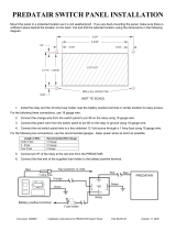
Wir ing De scrip tion for the 12- Pin Con nec tor
Pin Wire Color Con nects to
1
Red Battery (+) with 30-amp fuse
2
Gray Heater/AC output
3
Green/Blue Coil side - ignition (+) (and relay shown if manual transmission)
4
Red Battery (+) with 30-amp fuse
5
Red Battery (+) with 20-amp fuse
6
Brown Parking light output (+)
7
White/Green Key side - starter input (+)
8
Orange Accessory output
9
Brown Parking light output (+)
10
White/Blue Starter side - starter output (+)
11
Not used Not used
12
White/Brown Key side - ignition input (+)
4

Con trol Unit and Extended Range Re ceiver
The ACE 7500 con trol unit must be in stalled in side the ve hi cle, never un der
the hood or other simi larly hos tile en vi ron ment.
1. Select a mounting area, but do not affix the control unit until wiring and testing is complete.
2. Plug the 18” CliffNet DataPort Extension Cable into the control unit. Make sure the
receptacle end will be accessible after the dash has been put back. This eases later service.
3. Plug the extended range receiver in to the system and mount it away from the control unit.
4. Run the antenna rod up the window pillar and affix it to the windshield about an inch from
the roofline. Do not fold the excess cable or antenna wire. Do not make hard, sharp bends.
5

Wir ing De scrip tion for the 24- Pin Con nec tor
Pin Wire Color Con nects to
1
White/Blue Remotely Adjustable Dual-Zone Piezo Sensor input
2
White/Violet Pulse out before remote start (-) and upon disarming
3
Black/Gray RPM input
4
Blue/Green Reverse light input (+)
5
White Valet switch input (-)
6
Orange Glass Tampering Sensor input (-)
7
White/Black Hood trigger input (-)
8
Gray/Yellow Trunk trigger input (-)
9
Blue/White Brake light input (+) (and relay shown if manual transmission)
10
Black Ground for sensors, LED and PlainView 2 Switch
11
Red Power for Dual-Zone Piezo and Glass Tampering sensors
12
Black Ground (-)
13
Gray/Green Door lock output (+) or (-)
14
Green Armed output (-)
15
Violet/White Pulse out after remote start (-) and upon arming
16
Gray/Violet Auxiliary A output (-)
17
Gray/Orange Door unlock (+) or (-)
18
Red Battery (+) with 5-amp fuse
19
Violet LED output (+)
20
Yellow Siren (-)
21
Blue/Black Heater 2 relay output if needed (-)
22
Brown/Red Interior light supply input (+) or (-)
23
Gray Door trigger (+) or (-)
24
Blue/Orange Negative out when started
Starter and Ig ni tion Con nec tions
Im mo bi li za tion Cir cuits
1.In the underdash ignition switch wireloom, locate the one wire that carries +12V during
BOTH the cranking AND engine running cycles, and 0 volts when the ignition is off.
You may find two wires in the steering column wireloom that test this way. If
so, see the Secondary Ignition or Heater/AC wire section below.
2. Start the engine, then cut the ignition wire. The engine should stop running.
3. Connect the WHITE/BROWN wire to the key side of the ignition line.
4. Connect the GREEN/BLUE wire to the other side.
Starter Con nec tion
You MUST con nect the starter wires be fore the neu tral safety switch,
oth er wise the engine could be started while in gear. Be cer tain that both the
WHITE/GREEN and WHITE/BLUE wires are sol idly con nected.
1.Use a voltmeter to locate the one wire that carries +12V during the cranking cycle
ONLY. Cut this wire, then try to start the engine. It should not crank.
2. Con nect the WHITE/GREEN of the ACE 7500 wire to the key side of the cut starter line.
3. Connect the WHITE/BLUE wire of the ACE 7500 starter side of the cut starter line.
Heater/Air Con di tioner Con nec tion
1. Turn the vehicle’s heater/AC switch on and rotate the ignition key toward START one
increment at a time. Observe at which position the blower turns on.
2. Turn the engine OFF.
3. Connect the voltmeter black lead to ground and set the dial to DC volt.
4. Locate the one wire that carries +12V only when the ignition key is at the position where
the blower activates.
5. Cut the wire , then start the engine. The blower should not operate.
6. Connect the 12-pin connector’s GRAY wire to the heater/AC wire as shown on page 4.
6

Ac ces sory Line Con nec tion
Most vehicles have a separate accessory line to power the radio, electric windows, etc.
1. Turn on the ve hi cle’s ra dio and ro tate the ig ni tion key to ACC. The ra dio should turn on.
2. Lo cate the one wire that car ries +12V only when the ig ni tion key is in the ACC and ON
po si tions, but 0V while the key is in the START po si tion.
3. Cut this wire, then start the en gine. The ra dio should not op er ate.
4. Con nect the 12-pin connector’s OR ANGE wire to the ac ces sory wire as shown on page 4.
Sec on dary Ig ni tion or Heater/AC Wire
Many vehicles have two ignition or two heater/AC wires in order to split up the power
requirements of the temperature control system, onboard computers, fuel delivery system,
electronic transmission control, etc. If you are working on such a vehicle, you will find two
wires that both test as ignition lines or two wires that supply the heater/AC:
1. Connect the BLUE/BLACK wire to the coil of a relay for the second heater/AC line.
2. Connect the BLUE/ORANGE wire to the coil of a relay for the 2nd ignition line.
LED Status In di ca tor
Select a prominent location on the dash or console. Discuss placement with the owner.
1. Verify there is adequate space to accommodate the LED, then drill a 5/16” (8mm) hole
and route the wires through it.
2. Mate the LED connectors to the VIOLET and BLACK wire connectors as shown in the
diagram on page 5.
3. Press the LED into place.
Plain View 2 Coded Valet/Pro gram ming Switch
1. Discuss placement of the switch with the vehicle owner and avoid placing the switch
where it can be pressed accidentally.
2. Verify there is adequate space behind the selected location to accommodate the switch.
3. Drill a 5/16” (8mm) mounting hole, then insert the wires through the hole.
4. Mate the switch’s locking connectors to the WHITE and BLACK locking connector.
5. Remove the adhesive backing and press the switch into place.
Door Trig ger/In te rior Light Sup ply
The ACE 7500 has self-programming door trigger polarity. Door triggers on most autos are
negative (except most Rolls-Royce and Ford autos). To determine door trigger polarity, use
the following procedure:
1. Find the wire coming off the rear of the vehicle door switch.
2. Connect the negative voltmeter lead to ground.
3. Find the one wire that shows +12 volts when the switch is pressed in and 0 volts when
released. This is a negative trigger door wire.
4. If you don’t get the indications noted in step 3, find the one wire that shows 0 volts when
the switch is pressed in and +12 volts when released. This is a positive trigger door wire.
5. Connect the system’s thin GRAY wire to the door wire.
6. If the trigger wire is negative, connect the system’s BROWN/RED interior light supply
wire to ground. If the trigger wire is positive, connect the system’s BROWN/RED interior
light supply wire to the RED/WHITE wire.
NOTE: Clif ford Elec tron ics’ web site at www.clif ford deal ers.com (USER NAME
= roadshop PASSWORD = cliffg4) for Autho rized Clif ford Deal ers has de tailed
de scrip tions of wire col ors and lo ca tions for most for eign and do mes tic
ve hi cles. In stal la tion dia grams and pro gram ming pro ce dures for older Clif ford
prod ucts are also avail able. You can also obtain this information via the
Clifford Technical Support Computer Database or via our toll-free AutoFax or
our exclusive Circuit City Technical Support Hotline at 1-877-CLIFF-G4.
7

Door Locks
WARN ING: If the power door locks do not op er ate prop erly when the sys tem
is armed and dis armed, DO NOT USE THE VE HI CLE’S DOOR LOCK SWITCH!
Per ma nent dam age to the con trol unit or to the car’s elec tri cal sys tem and
lock ser vos will re sult. For assistance, call the Clif ford Tech ni cal Sup port
Hotline PRIOR to wir ing the door locks.
The ACE 7500 provides power door lock interface capabilities and is able to in ter face with
any power door lock con figu ra tion in clud ing
some Mer cedes Benz and Audi ve hi cles that
re quire a 3- second lock pulse (pulse du ra tion
is installer- programmable) and with any car
that requires double unlock pulsing (VW’s
and Nissans, for example). If the ve hi cle is
not equipped with power door locks, you
may op tion ally add up to four #60- 516 Door
Lock Ser vos to provide all the keyless entry
and other door locking/unlocking features
built into the ACE 7500. Some cars may
require adding relays.
De ter min ing the Lock Sys tem Type
1. Remove the door lock switch on the
driver’s side of the vehicle to reveal the
switch wires.
a.If there are four or more wires, make
the connections shown in Diagram 4
for reverse polarity.
b.If there are three wires, proceed to
step 2.
c. If the vehicle is a Nissan and it does
not have a door lock switch, find the
single wire in the driver’s kick panel
that shows ground when the locks are
unlocked and “open” when the locks
are locked. Cut this wire and make the
connections shown in Door
Lock/Unlock Diagram 3.
2. Connect the negative voltmeter lead to
ground and probe each wire while
locking/unlocking. If the voltmeter show
+12v while activating the switch, make
the connections shown in Door
Lock/Unlock Diagram 1 for positive
trigger. Otherwise, go to step 3.
3. Repeat step 2 with the negative
voltmeter lead connected to +12v. If
the voltmeter shows +12v while
activating the switch, make the connections shown in Door Lock/Unlock Diagram 2 for
negative trigger.
4. Locks controlled from the driver’s door key require installation of just one #60-516 servo
in the driver’s door. Vehicles without factory power locks require a servo in each door.
Mount the servo(s) and make the connections shown in Door Lock/Unlock Diagram 5 for
adding servos.
5. On a vacuum-pump-type Mercedes Benz or Audi, make the connections shown in Door
Lock/Unlock Diagram 6, then (if 1989 or older) program the system for a 3-second lock
pulse.
8

6. The ACE 7500 can also provide double
pulses (+ or -) for lock and/or (+ or -)
unlock that is required by some vehicles
(such as some Nissans, VWs, and Audis).
Wire the door locks following the steps
above and select the 2x lock and/or
unlock feature in installer-programming.
Park ing Lights
The ACE 7500 has built-in parking light
relays. To determine whether the vehicle has
single or dual parking light circuit(s), you
must access the fuse panel. A single circuit
has one fuse; a dual circuit has two.
Sin gle Park ing Light Cir cuit (Most
Japa nese and Ameri can Ve hi cles)
1.Turn on the parking lights and access the
Parking Light wiring in one of the
following locations:
n Near the head light switch
nIn the door sill har ness go ing to the
rear lights
n At any of the four Park ing Light bulbs
2. If working underdash, be sure to turn the
dashlight dimmer to its lowest setting.
3. Connect a voltmeter lead to ground and
find the single wire that shows +12v
when the parking lights are on and 0
volts when they are off.
4. Connect both
of the BROWN wires to
the parking light wires.
5. Connect the RED 18AWG wire from the
12-pin connector to the vehicle battery
positive (+) terminal via the supplied
20-amp fuse and fuseholder.
Dual Park ing Light Cir cuit (Most
Euro pean Ve hi cles)
1. Turn on the parking lights and access the Parking Light wiring in one of the following
locations:
n Near the head light switch
nIn the door sill har ness go ing to the rear lights
n At any of the four Park ing Light bulbs
2. If working underdash, be sure to turn the dashlight dimmer to its lowest setting.
3. Connect a voltmeter lead to ground and find the two wires that show +12v when the
parking lights are on and 0 volts when they are off.
4. Connect one lead to the left-side Parking Light circuit and connect the other lead to the
right side circuit.
5. Connect the RED 18AWG wire from the 12-pin connector to the vehicle battery positive
(+) terminal via the supplied 20-amp fuse and fuseholder.
NOTE: Never con nect the RED 18AWG wire to ground. Al ways pick up the
positive- switching park ing light line(s).
9

Fac tory Theft De ter rent By pass
The wiring noted be low is to dis arm a ve hi cle’s fac tory sys tem to per mit re mote start ing.
For more information on factory theft deterrent bypass, check your Clifford
Tech Support Database, visit www.clifforddealer.com (USER NAME =
roadshop PASSWORD = cliffg4) or call our toll-free Circuit City Technical
Support Hotline or AutoFax at 1-877-CLIFF-G4.
1. The BLUE/ORANGE wire is a negative out whenever the vehicle is remotely started. It
can be used for extra ignition relays or for factory alarm bypass.
2. The WHITE/VIOLET wire is a negative pulse out just prior to remote engine starting. It
can be used to pulse a factory disarm wire or unlock the doors. This wire also pulses when
the ACE 7500 is disarmed using the remote.
3. The VIO LET/WHITE wire is a nega tive pulse out af ter re mote en gine start ing. This can
be used to lock the doors after remote starting if the doors had been unlocked prior to
starting. This wire also pulses when the ACE 7500 is armed using the remote.
Re verse Lights
1. Ver ify that the re verse lights il lu mi nate when the trans mis sion is put in re verse.
2. Find the one wire in the kick panel that reads +12V only when the transmission is in reverse.
3. Con nect the BLUE/GREEN wire to the re verse light as shown on page 5.
Brake Lights
If working on a manual transmission vehicle, add a 3-amp diode terminal 30
of an optional relay as shown on pages 4-5 and connect it into the
BLUE/WHITE brake input wire. See also Manual Transmission section below.
1. Turn the ignition ON and press the brake pedal to make sure the brake light turns on.
2. Connect the black lead of the voltmeter to ground and set the dial to DC volt.
3. Probe one of the two wires at the brake pedal switch with the voltmeter red lead. The
voltmeter should read +12V when you press the brake pedal; 0 volts when released.
4. Connect the BLUE/WHITE wire to the brake light wire as shown on page 5.
Man ual Trans mis sion
1. Find two wires going in to a connector
on the clutch pedal.
2. Unplug the clutch pedal connector,
then try to start the vehicle while
pressing the clutch pedal. The engine
should neither start nor crank.
3. Connect the BLUE/ORANGE wire to
an optional relay as shown.
4. Turn on the ignition.
5. Find the one wire near the emergency brake that carries +12V when
the emergency brake is engaged and 0V when it is disengaged.
6. Con nect the emergency brake wire to terminal 86 of a relay as shown on pages 4-5.
Die sel En gine
Use the built-in timer to crank the en gine 20 sec onds af ter the remote start command is received .
Using the 20 second delay:
Using the Installer-Programming instructions on page 17, set column 2, row 5 to “Diesel
Engine,” then immediately program RPMs, or use the CliffNet Wizard Pro installation
software to program the system. The CliffNet Wizard PRO will also allow you to customize
the delay to other than 20 seconds.
10

RPM Moni tor ing
The ACE 7500 monitors RPM which is REQUIRED for the operation of the remote engine
starting electronics as well as the anti-carjacking electronics and RPM-dependent AutoLock
feature. After powering up the system, you must perform the MANDATORY RPM
PROGRAMMING noted on page 13. Some newer vehicles do not have a conventional coil
marked (+) and (–). In these instances, you will need to locate the tach wire:
1. Try to locate the distributor cap which all spark plug wires run in to. There should be the
same number of plug wires as the number of cylinders. If there is an extra plug wire, the
vehicle has a separate coil.
2. Follow the extra plug wire to the coil module, which will have two or more wires.
a.If there are only two wires: one is the ignition, the other wire is the negative coil wire.
b.If there are more than two wires, only an oscilloscope will be 100% accurate in locating
the tach wire, but a digital voltmeter will often suffice. Set the meter to read AC
voltage, connect the negative lead of the meter to ground and probe the wire with the
positive lead. The wire that has the highest AC voltage while the engine is running is
usually the tach wire.
3. If the vehicle does not have a separate coil, look for the tach wire in a plug coming out of
the distributor. If no distributor can be found, there may be multiple coils. Each coil usually
has an ignition and a negative coil wire. The system will learn a single or multiple coil system.
4. If no coil or distributor can be found or reached, use the #60-226 RPM Alternator Sensor.
5. You can often connect to the negative side of any fuel injector. Most injectors are screwed
directly into the engine and have two wires. One is ignition and usually has a color common
to all, the other is the negative side and can be tested as described in step 2b above.
In stal la tion Op tions
1.In stal la tion Op tion 1 — Negative Coil
Con nect the BLACK/GRAY wire to the nega tive ter mi nal of the ig ni tion coil, nor mally
marked (–).
2. In stal la tion Op tion 2 — Fuel Injector Wire
a.On many engines with electronic fuel injection, there are two wires going to each
injector: a fuel-injector wire and a common ignition wire. The common ignition wire is
usually the same color at each injector (and may also be the same color as the ignition
line in the steering column). The injector wire is the other wire.
b.Connect the BLACK/GRAY wire to one of the injector wires.
3.In stal la tion Op tion 3 — Tachometer Terminal (Not all cars have a tachometer terminal
— mostly older GM models have a tachometer terminal)
a. Locate the tachometer terminal on the distributor cap (this may be marked “tach”).
b.Connect the BLACK/GRAY wire to the tachometer terminal.
4. In stal la tion Op tion 4 — Optional Alternator Sensor (#60-226)
Follow the instructions provided in the Alternator Sensor kit.
5. In stal la tion Op tion 5 — Optional RPM Monitoring Module (#60-521)
a.Locate the coil wire that connects to the distributor.
b.Attach the RPM Monitoring Module to the coil wire.
c. Connect the RED, BLACK and WHITE wires on the RPM Monitoring Module to the
RED, BLACK and BLACK/GRAY wires of the system.
Trunk Trig ger
Vehicles with a ground-switching trunk light will interface directly with the ACE 7500 (on
positive switching Rolls-Royce vehicles, use a relay to invert polarity). The switch may be
located in or near the trunk latch or at the trunk light. If a switch cannot be located, you
must add a pin switch in a location away from water channels.
NOTE: If the ve hi cle has a dash board trunk ajar in di ca tor, in stall a 1- amp
di ode be tween the light and switch with the di ode band to ward the switch.
1. Connect the GRAY/YELLOW wire to the trunk switch (between the diode and switch).
11

Re motely Ad just able Dual- Zone Piezo Sen sor
Mount this sensor in the passenger compartment, not in the engine compartment.
1. Firmly mount the sensor near the base of the steering column (if the steering column has a
rotating sleeve, firmly screw the sensor to the interior firewall, kick panel or trunk wall).
2. Mate the sensor to the connector with the BLACK, RED, and WHITE/BLUE wires.
3. After power-up, adjust the sensor as noted on page 15.
Glass Tam per ing Sen sor
Mount this sensor in the passenger compartment, not the engine compartment.
1. Mount the microphone holder so that it points into the passenger compartment, but will
not be exposed to direct sunlight.
2. Plug the microphone into the sensor (an optional second microphone can be added for
vans and other large vehicles for increased sensitivity and better discrimination).
3. Mate the sensor to the connector with the BLACK, RED and ORANGE wires.
Aux il iary A with Se lecta ble Out put Type with AutoAc ti va tion
The Auxiliary A output (GRAY/VIOLET wire) can be programmed as either pulsed, latched
or timed and can be programmed to operate only when the system is disarmed (e.g., for use as
a remote trunk release). Note that the selectable output type is only programmable using the
CliffNet Wizard Pro. Auxiliary A output is activated by pressing the button on the
companion remote control or button 2 on the master remote control. The factory setting is
pulsed output (1 second ground). The latched output stays at ground until the button or
button 2 is pressed a second time, and the timed output stays at ground for any selected
duration between one second and four minutes. Current is limited to 0.15 amp. You can also
set this output to automatically activate every time the system is remotely-armed (perfect if
wiring as a timed output to close the electric windows and sunroof on European vehicles that
have an all-close feature). See Installer-Programmable Features on page 17 to change the type
of output, set AutoActivation and/or disable operation while the system is armed.
Euro pean Ve hi cle Win dow/Sun roof All-Close
If the door key can close the power windows/sunroof, you can make them automatically close
upon remote arming (CliffNet Wizard is required to program this feature):
1. Find the wire that shows +12V or ground when the key is held to lock in the door cylinder.
2. Tap a wire in to this wire and connect to terminal 30 of the relay.
3. If the wire shows (-) when the key is turned, connect terminal 87 to (-). If the wire shows
+12V when the key is turned, connect terminal 87 to 12V.
4. Connect the output of the alarm that can be set to AutoActivate to terminal 85.
5. Connect +12V to terminal 86.
8. Turn on the AutoActivate timed accessory upon remote arming feature as noted in the
installation manual for the alarm under Installer-Programmable Features.
8. Set the timer duration to proper time interval with two seconds added to that time
interval.En gine Bay Con nec tions.
9. Set Auxiliary Output A to Timer using the CliffNet Wizard.
En gine Com part ment Con nec tions
Hood Trig ger
Vehicles with a ground-switching hood pin switch interface directly with ACE 7500 (on positive
switching Rolls-Royce vehicles, use a relay to invert polarity). If a switch cannot be located, you
must add a pin switch in a location away from water channels.
1. Connect the WHITE/BLACK wire to the hood pin wire.
12

High Out put In sig nia Si ren
Mount the siren in the engine compartment away from hot or moving parts and where it
cannot be reached from under the vehicle, preferable opposite the exhaust system. Point the
siren down to avoid water collection (see the illustration).
1. You must firmly secure the siren to the engine bay firewall or a fender well using all three
sheet metal screws supplied.
2. Us ing the sup plied con nec tor, fasten the BLACK wire coming from the siren to the
YELLOW wire from the 24-pin connector on the control unit.
3. Connect the RED wire to the 5-amp fuse that is connected to the battery positive cable
clamp.
Fi nal Wir ing Con nec tions
1. Connect the two 14AWG RED wires from the 12-pin connector to the 30-amp fuseholders as
shown on page 4.
2. Connect the 16AWG RED wire from the 12-pin connector to the 20-amp fuseholder.
3. Connect the 18AWG RED wire from the 24-pin connector to the 5-amp fuseholder.
4. Attach the four fuseholders to the battery positive cable clamp.
5. Attach the 18AWG BLACK wire from the 24-pin connector to the battery negative cable
clamp.
NOTE: Power and test ac ces so ries af ter the ba sic sys tem has been tested.
In di vidu ally fuse all ac ces sory power and fuse panel con nec tions.
Smart Powe rUp™ 2
SmartPowerUp 2 ensures that the system powers up in the same state (disarmed, armed or valet
mode) it was in when power was removed. When you first power up the ACE 7500, it will silently
enter the disarmed state.
MAN DA TORY RPM PRO GRAM MING
NOTE: ACE 7500 will not operate properly without this pro gram ming step.
NOTE: If working on a diesel engine vehicle, you must first set the system for
diesel operation using the Installer-Programmable Features on pages 17-18.
1. Drive the vehicle outside the RoadShop bay and allow the engine to warm up.
2. With the engine still running and the transmission in PARK or NEUTRAL, enter the
valet code (✱✱ blank) on the PlainView 2 switch and immediately hold the ✱ button.
You’ll hear one chirp to indicate user programming mode.
3. KEEP HOLDING (about 12 more seconds) until you hear the 3-chirp installer
programming mode confirmation.
4. Select “Program RPM”: Press the PlainView switch blank button once, wait for 1 chirp,
then ✱ 5 times and wait for the 2 chirps to confirm that the RPMs have been set (if you
hear one chirp instead, check connection of the BLACK/GRAY wire).
5. If working on an automatic transmission vehicle, you must also set the transmission type
to automatic. See Installer-Programmable Features on pages 17-18.
6. Turn the ignition off to exit installer program mode.
De layed Cour tesy Lights
Some vehicles have a courtesy light delay or dimming circuit that interferes with an alarm being
able to detect the door trigger upon remote arming. If the delay or dimming lasts more than 5
seconds, turn on the Delayed Courtesy Lights feature noted in the Installer-Programmable
Features section on page 17. Please note that since this feature sets the system to arm the instant
the courtesy lights turn off, the Door Ajar Warning feature will not be available.
13

Re mote Con trol Op era tion
The ACE 7500 comes with two ergonomically designed remote controls. Up to two more
ACG 2 remote controls can be added to the ACE 7500 system (older Clifford ACG and
non-ACG remotes are not compatible with the ACE 7500).
If a remote control is ever lost or stolen, its identity can be erased from the system memory so
that the missing remote control can never again be used to control the system. To do so, just
use the Clear All Remotes feature noted in the User-Programmable Features chart (blank x 2,
✱ x 6)on page 16.
Com pan ion & Mas ter Re mote Con trols
The icon buttons on the companion remote control operate
arming/disarming (the lock/unlock button), the auxiliary output (the trunk
button), remote engine starting (the snowflake button) and the
AutoStart/Manual Transmission SafeStart mode (the double snowflake
button). In addition, other system features can be accessed by pressing
combinations of these buttons. For example, to silently arm
or disarm, simultaneously press the ✱ and the button.
The master remote control can operate higher level
functions, such as sensor adjustment, by shifting the 4
buttons up to a higher level via the LevelShift button on the
side of the remote control. For example, to access the sensor
adjustment mode (described on the following page), you
would press the side LevelShift button 3 times, then press
button 3.
QUICK REF ER ENCE: RE MOTE CON TROL FUNC TIONS
Func tion
Companion
Remote
Button(s)
Master Remote
LevelShiftButton
Arm or dis arm and lock or un lock the doors
no 1
Optional wired ac ces sory #1* (usu ally optional trunk re lease)
no 2
Silently arm or dis arm and lock or un lock the doors
+
✱
no 3
Remotely start the engine
✱
no 4
Unassigned*
+
✱
1 time 1
Unassigned or SmartWin dows 4 ac ces sory full open or vent*
+
1 time 2
Unassigned*
+
✱✱
1 time 3
Unassigned*
1 time 4
Remote valet mode entry/exit
✱✱ + ✱
2 times 1
Unassigned*
✱✱ +
2 times 2
LowTemp/Battery AutoStart or manual transmission SafeStart
✱✱
2 times 3
Unassigned*
2 times 4
Unassigned*
3 times 1
Unassigned*
3 times 2
Remotely adjust sensitivity of the Dual-Zone Piezo Sensor
3 times 3
Unassigned*
3 times 4
*These but tons/chan nels can be as signed to con trol Clif ford G4 sys tems and ac ces so ries on the customer’s other ve hi cles.
14

Sen sor Ad just ment
1.Disarm the system with the master remote control.
2. On the master remote, press the LevelShift three times, then button 3. You will hear one
chirp and the LED will turn on.
3. Test the primary (alarm) zone, by firmly “thumping” the top of the A-pillar (the area
between the side windows near the roof) with the heel of your fist. If the impact is strong
enough to trigger the primary zone, you will hear a siren chirp. To change sensitivity, press
button 4 to reduce sensitivity, button 2 to increase sensitivity. Two chirps will
acknowledge each sensitivity increase, one chirp will confirm each decrease. You can test
the new setting by again thumping the top of the A-pillar. You may now press button 3 to
adjust the warning zone (as noted in 3a. below), or press button 1 to fully exit the sensor
adjustment mode (you will hear 3 chirps).
a.For the Piezo Sensor warning zone, press button 3 (you’ll hear 1 chirp). Then use the
same procedure as above, but thump less forcefully for the warning zone. When done,
press button 1 to reselect the primary zone (you will hear 2 chirps), then button 1 again
to fully exit sensor adjustment mode (you will hear 3 chirps).
4. For the Glass Tampering Sensor, a light tap on the window with a coin should not trip the
system, but a firm tap should.
5. Turn the Glass Tampering Sensor’s adjustment screw counterclockwise to decrease
sensitivity, clockwise to increase (you may also reposition the sensor’s microphone[s]).
Eight- Event To tal Re call
The system’s nonvolatile memory records the identity of the last eight activated or
malfunctioning triggers and sensors:
1. With the ignition OFF, press and hold the blank side of the PlainView 2 Switch.
2. Use the remote control arm, and then again to disarm, and then release the button.
3. The LED will flash 1–10 times, pause, then flash 1–10 times, etc. Write down the number
of flashes in each cycle.
4. Refer to the following chart. The first number you wrote down was the most recently
activated trigger or sensor. The next number is the second most recent, and so on up to as
many as the last eight activations.
LED flashes Trig ger/sen sor in di ca tion
2 flashes Dual-Zone Piezo Sensor
3 flashes Glass Tampering Sensor
4 flashes Door trigger
5 flashes Trunk trigger
6 flashes Hood trigger
7 flashes An attempt was made to turn on the ignition while the system was armed
9 flashes BlackJax activation
10 flashes System power interruption
Pro gram ma ble Fea tures
ACE 7500 comes from the factory with its features preprogrammed as noted in bold text in
the tables on pages 16 and 17.
Us ing the Cliff Net Wiz ard PRO
CliffNet Wizard PRO provides an intuitive access to all installer and user-programmable
features through a user-friendly, graphical user interface and provides extensive diagnostic
capabilities. See www.clifforddealer.com (USER NAME = roadshop PASSWORD = cliffg4) to
download a free copy of the program.
15

Pro gram ming the User- Selectable Fea tures
1. Write down the column (across) number and row (down) number of the feature(s) you
wish to program.
2. Turn the ignition to the “ON” position or start the engine.
3. Enter the factory preset valet/programming code of “2” by pressing the PlainView 2
Switch’s ✱ button two times, then press the blank button.
4. After entering the code, press and hold the ✱ for about 3 seconds until you hear one siren
chirp and the LED turns on to confirm the system is in the “Feature Select” position.
5. Select the feature column: Press the blank PlainView 2 switch button the number of times
indicated for that column. Pause. You will then hear the same number of chirps as the
column number you have selected, audibly confirming your selection.
6. Within five seconds, select the feature row: Press the ✱ button the number of times
indicated for that row. You’ll hear a chirp each time you press the ✱ button to help you
count.
7. If there is a NOTE for the selected feature, perform the actions noted.
8. Pause. You will hear either one or two chirps: two chirps = ON, one chirp = OFF.
9. You can select another feature, or you can exit program mode:
a.To select another feature in that same column, repeat step 6 within the next five
seconds (after five seconds, three chirps indicate that the ACE 7500 is now back in the
“Feature Select” position).
b.To select a different feature column, repeat step 5.
c.To exit program mode, turn the ignition off (you’ll hear three chirps and the LED will
turn off to indicate exit of program mode), or wait 60 seconds and the ACE 7500 will
automatically exit program mode.
User- Programmable Fea tures
User- Programmable Fea tures (1 Chirp = OFF, 2 Chirps = ON)
Fea ture
Select
Blank x 1 Blank x 2 Blank x 3 Blank x 4
✱ x 1
AutoProgram
New Master
Remote
NOTE 1
Chirps
(Off/On)
(1/2 chirps)
AutoArming
(Off/On)
(1 chirp/2 chirps)
Arm/Disarm
w/Secondary Remote
NOTE 5
✱ x 2 NOT USED
Headlight
Reminder
(Off/ On)
AutoArm & Lock
(Off/On)
Auxiliary A Accessory
w/Secondary Remote
NOTE 6
✱ x 3
Siren Sounds*
(Always/Trigger)
(1/2chirps)
Remote Valet
Feature
(Off/On)
Entry Delay
(Off/On )
Silent Arm/Disarm
w/Secondary Remote
NOTE 6
✱ x 4
Si ren Du ra tion
(30 /60/90 sec)
(1/2/3 chirps)
AutoStart
(Neither/Battery/
Temperature/Both)
(1/2/3/4 chirps)
FACT
(Off/On)
Manual Start Enable
w/Secondary Remote
NOTE 6
✱ x 5
AutoLock
(Off/Instant/RPM)
(1/2/3 chirps)
BlackJax
(Off/On)
Delayed
Accessory Power
(Off/On )
Remote Start
w/Secondary Remote
NOTE 6
✱ x 6
AutoUnlock
(Off/On)
Clear All Remotes
NOTE 3
NOT USED
SmartWindows 4
w/Secondary Remote
NOTE 6
✱ x 7
Re set All to
Fac tory Set tings
NOTE 2
Valet Code
NOTE 4
NOT USED
Remote Valet Mode
w/Secondary Remote
NOTE 6
*Re quires Self- Powered Smart Si ren 4
16

n NOTE 1: Press button 1 on the 16-channel master remote, you will hear one chirp.
Press button 1 again , you will hear two chirps.
n NOTE 2:You will hear two chirps when all features are reset. Valet code and remote
controls are not changed.
n NOTE 3: When you hear two chirps, all remote controls will have been erased from
the system memory. You must now add the new and/or existing remote controls to the
system (i.e., Program each remote that will be used with the ACE 7500).
n NOTE 4: Immediately press the blank button, then immediately enter the new PIN
code. (Example: To enter 4301, you would press: ✱✱✱✱ blank, ✱✱✱ blank, blank, ✱
blank.) Wait for the 2-chirps, then turn off the ignition (3-chirps). IMPORTANT :
You must immediately test the new PIN code: Turn on the ignition, enter the new code,
then press and hold the blank button for 4 seconds. The LED will light to indicate that
the system is in valet mode, enter the code again to exit valet mode. If the LED does
not illuminate, the new code you programmed and the one you just entered do not
match. In such a case, the system will revert to the previous code.
n NOTE 5: Programs a companion remote or any other type remote from another G4
system to arm/disarm this system. For instance, to set button ✱ of the other car’s remote
to arm/disarm this system , select column 4, row 1, then press button ✱ of the other car’s
remote. You’ll hear 1 chirp. Immediately press button ✱ of the other car’s remote
again. You’ll hear 2 chirps.
n NOTE 6: Programs a companion remote or any other type remote from another G4
system to perform the noted function on this system. Select the row and column number,
then transmit the unused button/channel on the other remote that you want to perform
that function. The system will respond with the same number of chirps as the row
number. Please note that you must first set a button on the remote that will arm/disarm
the system (column 4, row 1) before these others will be accepted.
Installer- Programmable Fea tures
To access the installer-programmable features:
1. Turn on the ignition.
2. Enter the valet code (✱✱ blank) on the PlainView 2 switch and immediately hold the ✱
button on the PlainView 2 switch.
3. You’ll hear one chirp after about 3 seconds to indicate user programming mode. KEEP
HOLDING (about 12 more seconds) until you hear the 3-chirp installer programming
mode confirmation.
4. Select the feature column: Press the blank PlainView 2 switch button the number of times
indicated for that column. Pause. You will then hear the same number of chirps as the
column number you have selected, audibly confirming your selection.
5. Within five seconds, select the feature row: Press the ✱ button the number of times
indicated for that row. You’ll hear a chirp each time you press the ✱ button to help you
count.
6. Pause. You will hear either one or two chirps: two chirps = ON, one chirp = OFF.
7. You can select another feature, or you can exit program mode:
a.To select another feature in that same column, repeat step 5 within the next five
seconds (after five seconds, three chirps indicate that the ACE 7500 is now back in the
“Feature Select” position).
b.To select a different feature column, repeat step 4.
c.To exit program mode, turn the ignition off (you’ll hear three chirps and the LED will
turn off to indicate exit of program mode), or wait 60 seconds and the ACE 7500 will
automatically exit program mode.
17

Ta ble of Installer- Programmable Fea tures (1 chirp = OFF, 2 chirps = ON)
Fea ture
Select
Blank x 1 Blank x 2 Blank x 3
✱ x 1
Single /Double
Lock Pulse (1 /2 chirps)
NOT USED
Door Ajar Warning
/Delayed Courtesy Lights
(1/2 chirps)
✱ x 2
Single /Double
Unlock Pulse (1/2 chirps)
Manual/Auto Transmission
(1/2 chirps)
Auxiliary A (trunk
release) Interlock Off/On
✱ x 3
Lock/Unlock Pulse
1 second /3 second
(1 /2 chirps)
NOT USED NOT USED
✱ x 4
Pos/Neg Lock Polarity
(1/2 chirps)
NOT USED NOT USED
✱ x 5
Program RPM
See Mandatory RPM
Programming page 13)
Diesel/Gas Engine*
(1/2 chirps)
AutoActivate Auxiliary A
Off/On
✱ x 6 NOT USED NOT USED
Program SmartWindows 4
* You must pro gram RPMs af ter chang ing this set ting.
Sys tem Check list & Trou ble shoot ing
The fol low ing check list will as sure that you have in stalled the ACE 7500 cor rectly. Each
suc ces sive step re quires that the pre vious step has been com pleted as in di cated.
Step 1: Re- enable the cour tesy lights.
In step 1 of the Important Information sec tion, the in te rior cour tesy lights were disabled. You
must now re-enable the courtesy lights by re placing the fuse you re moved or re set the
cour tesy light switch back to its nor mal “DOOR” po si tion bef ore pro ceed ing.
Step 2: Test the im mo bi li za tion cir cuits.
Arm the ACE 7500 with the remote from inside the vehicle and wait 10 seconds. Turn the
ignition to the “ON” position.
n Engine does not respond. This is the correct response, proceed to step 3.
n Engine starts or cranks. The starter/ig ni tion/fuel pump or immobiliza tion cir cuits have
been mis wired. Care fully re test the ve hi cle wires as noted in the Starter and Ig ni tion
Connections section on page 6. Be sure the ignition input/output is correct!
n If engine still starts or cranks after retesting all the wiring, check the power and ground
connections. Make sure fuses are in the fuseholders, verify the control unit connectors are
securely fastened, verify the ignition input and output wires are connected to the true
ignition line instead of a 12V or accessory line, and verify the transmitters are programmed.
Step 3: Test the chirps.
Close all doors and arm the sys tem with the remote control.
n 2 Chirps: This is the correct response. Proceed to step 4.
n 4 Chirps: If 4 chirps im me di ate ly or 5-10 sec onds af ter the ini tial two chirps, a trig ger
or sen sor is open or active, or the ve hi cle has de layed cour tesy lights and the De layed
Cour tesy Lights fea ture has not been programmed on. Dis arm with the re mote, en ter the
ve hi cle and turn on the ig ni tion. The LED will flash 1–10 times, pause, then re peat the
same number of flashes (the flash cy cle re peats five times for your con ven ience). Refer
to the chart on page 15 to interpret the flashes.
n If the door trig ger is in di cated, ac ti vate the de layed cour tesy lights fea ture.
n No chirps. Ver ify the Chirps fea ture (col umn 2, row 1) is on and check siren connections.
18

NOTE: If none of the troubleshooting techniques described corrects the
problem, perform the following diagnostics:
n Make sure the fuses are in the fuse hold ers and check the power and ground con nec tions.
nVer ify that the con trol unit con nec tors are prop erly in serted into the con trol unit.
n Verify the ig ni tion in put and out put wires are con nected to the true ig ni tion line instead
of a +12V line. See the Starter and Ig ni tion Connections section.
n Ver ify that the trans mit ters are pro grammed cor rectly.
NOTE: If the 20- amp fuse blows upon arm ing:
nDisconnect the ACE 7500’s two parking light wires, replace the 20-amp fuse and rearm.
If the fuse does not blow, one (or both) of the ve hi cle’s parking light wires is short ing.
n If the fuse blows while the parking light wires are dis con nected, the door locks are not
wired cor rectly. Re con nect the ve hi cle’s power lock ing sys tem to its origi nal con di tion,
then re test the volt ages as in di cated in the Door Locks sec tion.
Step 4: Test the park ing lights.
Arm the sys tem with the re mote con trol.
nTwo flashes. This is the correct response, proceed to step 5.
n One flash. If the parking lights flash only once, the ACE 7500 had pre vi ously
AutoArmed it self pas sively and by press ing but ton 1 the sys tem dis armed (re mote
dis arm ing is ac knowl edged with one parking light flash). Re peat step 1.
n No flashes. If no flashes, ver ify the parking light bulbs are op era tional. If not, they must
be re placed. If so, see the Parking Lights sec tion.
n Only one side flashes. If only the right or the left side parking lights flash, see the
Parking Lights sec tion.
Step 5: Test the door locks.
Arm the sys tem by press ing but ton 1 on the re mote con trol.
nDoors lock. This is the correct response, proceed to step 6.
n Doors do not lock. You ei ther se lected the wrong lock dia gram, programmed the wrong
lock polarity or con nected the wires in cor rectly. Re con nect the ve hi cle’s lock ing sys tem
to its origi nal con di tion, then re test as in di cated in the Door Locks sec tion.
WARN ING: If the doors do not lock, DO NOT ac ti vate the ve hi cle’s lock
switches. Do ing so may dam age the ACE 7500 con trol unit, the ve hi cle’s
elec tri cal sys tem and/or the power lock servo mo tors.
n Doors unlock. You ei ther se lected the wrong door lock dia gram or con nected the wires
in cor rectly. Re con nect the ve hi cle’s power lock ing sys tem to its origi nal con di tion, the n
re test the volt ages as in di cated in the Door Locks sec tion and wire the locks as in di cated.
n Only one door locks. You ei ther se lected the wrong door lock dia gram or con nected
the wires in cor rectly. Re con nect the ve hi cle’s power lock ing sys tem to its origi nal
con di tion, then re test the volt ages as in di cated in the Door Locks sec tion.
Step 6: Test the PlainView 2 Switch .
Test switch operation by entering programming mode as noted on page 16. If no response:
n Verify the WHITE/BROWN wire has +12V when the ignition is ON and 0V when
OFF. If not refer to Starter and Ig ni tion Connections section on page 6.
n Verify the WHITE wire rests at +5V, shows +3V when pressing the switch’s ✱ button
and 0V when pressing the blank button. If not, test the switch’s BLACK wire. It should
read 0V at rest, 0V when pressing ✱ , and 0V when pressing the blank button. If the
BLACK wire tests incorrectly, check the ground circuit. If both wires test correctly, the
valet code has been changed. Use CliffNet Wizard PRO to reset the PIN code.
19
/