Dunkirk H2OST60 Installation, Operation & Maintenance Manual

Type
Installation, Operation & Maintenance Manual
H
2
O
Hot Water Storage/
Booster Tanks
For Single Tank Installations
INSTALLATION, OPERATION &
MAINTENANCE MANUAL
30, 40, 60, 80, 115 Gallon
L = Low Boy Prole
C = Commercial Pipe Connections
Conforms to UL STD 174 and NSF/ANSI 372
Certied to CAN/CSA STD C22.2 No. 110-94
ECR International Inc.
2201 Dwyer Avenue, Utica, NY 13501
Tel. 800 253 7900
www.ecrinternational.com
PN 615000055 REV. D [04/01/2020]
Information and specications outlined in this manual in effect at the time of printing of this manual. ECR International,
Inc. reserves the right to discontinue, change specications or system design at any time without notice and without in-
curring any obligation, whatsoever.
3
I. General Information ..........................................................................................................................................3
II. Important Safety Instructions
..........................................................................................................................4
III. Pre-Installation Considerations
.......................................................................................................................5
IV. Electrical
...........................................................................................................................................................8
V. Operation
..........................................................................................................................................................8
VI. Maintenance
.....................................................................................................................................................9
Table of Contents
Hazard Denitions
The following dened terms are used throughout this manual to bring attention to the presence
of hazards or various risk levels or to important information concerning the life of the product.
Indicates a presence of hazards that WILL cause severe personal injury,
death or substantial property damage.
Indicates a presence of hazards that CAN cause severe personal injury,
death or substantial property damage.
Indicates a presence of hazards that will or can cause minor
personal injury, or property damage.
Indicates special instructions on installation, operation or
maintenance that are important but not related to personal injury
or property damage.
SAVE THESE INSTRUCTIONS
MODELS
H
2
OST80
H
2
OST80C
H
2
OST115
H
2
OST115C
H
2
OST30
H
2
OST40
H
2
OST60
H
2
OST60L
DANGER
!
WARNING
!
CAUTION
!
NOTICE
4
I. General Information
IMPORTANT INFORMATION – READ CAREFULLY
NOTE: The equipment shall be installed in accordance with those installation regulations required in the area where the
installation is to be made. These regulations shall be carefully followed in all cases. Authorities having jurisdiction shall be
consulted before installations are made.
All wiring on storage tanks shall be in accordance with the National Electrical Code and/or local regulations.
WARNING
!
Improper installation, adjustment, alteration, service or maintenance can cause property damage, personal injury, or loss
of life. Read and understand the entire manual before attempting installation, start-up, operation, or service. Installation
and service must be performed only by an experienced, skilled installer or service agency.
This storage tank contains very hot water under high pressure. Do not unscrew any pipe ttings or attempt to disconnect
any components of this storage tank without positively assuring that the water is cool and has no pressure. Always wear
protective clothing and equipment when installing, starting up or servicing this storage tank to prevent scalding injuries.
Do not rely on the pressure and temperature gauges to determine the temperature and pressure of the storage tank. This
storage tank contains components that become very hot when the boiler is operating. Do not touch any components un-
less they are cool.
Failure to follow all instructions in the proper order can cause personal injury or death. Read all instructions, including all
those contained in component manufacturers’ manuals before installing, starting up, operating, maintaining, or servicing
the storage tank.
CAUTION
!
To reduce the risk of excessive pressures and temperatures in this storage tank, install temperature and pressure
protective equipment required by local codes but no less than a combination temperature relief valve certied by a
nationally recognized testing laboratory that maintains periodic inspection of production of listed equipment or materials,
as meeting the requirements for Relief Valves and Automatic Shutoff Devices for Hot Water Supply Systems, ANSI Z21.22-
latest edition. This valve must be marked with a maximum set pressure not to exceed the marked working pressure of
the storage tank. Install the valve into an opening provide and marked for this purpose in the storage tank, and orient it
or provide tubing so that any discharge from the valve will exit only within 6 inches above, or at any distance below, the
structural oor, and cannot contact any live electrical part. The discharge opening must not be blocked or reduced in size
under any circumstances.
Improper water quality will reduce the life of the storage tank. Hard water, sediment, high or low PH and high levels of
chlorides in the domestic water should be avoided. Be sure that PH levels fall between 6 and 8 and dissolved chlorides
are less than 100 ppm. A lter must be used where sediment is greater than 5 microns in size in the water supplied to
the unit. A water softening system is recommended for areas with hard water. In cases where water quality is unknown, a
qualied water treatment expert should be consulted.
NOTICE: Damage to tanks caused by improper water quality is not covered under the warranty.
5
Hydrogen gas can be produced in a hot water system served by this storage tank that has not been used for a long period
of time (generally two weeks or more). Hydrogen gas is extremely ammable. To reduce the risk of injury under these
conditions, it is recommended that the hot water faucet be opened for several minutes at the kitchen sink before using
any electrical appliance connected to the hot water system. If hydrogen is present, there will probably be an unusual
sound such as air escaping through the pipe as the water begins to ow. There should be no smoking or open ame near
the faucet at the time it is open.
II. IMPORTANT SAFETY INSTRUCTIONS
When using electrical appliances, basic safety precautions to reduce the risk of re,
electric shock, or injury to persons should be followed, including:
READ ALL INSTRUCTIONS BEFORE USING THIS STORAGE TANK.
1.
Install or locate this storage tank only in accordance with the provided installation instructions
2.
Use this storage tank only for its intended use as described in this manual.
3.
As with any appliance, close supervision is necessary when used by children.
4.
Do not operate this storage tank, if it is not working properly, or if it has been damaged or dropped.
5.
This storage tank should be serviced only by qualied personnel. Contact nearest authorized service facility for exami-
nation, repair, or adjustment.
WARNING
!
DO NOT store or use gasoline or other ammable vapors or liquids in the vicinity of this or any other appliance.
If you smell gas vapors, DO NOT try to operate any appliance - DO NOT touch any electrical switch or use any phone in
the building. Immediately, call the gas supplier from a remote located phone. Follow the gas suppliers instructions or if
the supplier is unavailable, contact the re department.
This storage tank is supplied with an adjustable thermostat to control the water temperature. Hot water temperatures re-
quired for automatic dishwashers and laundry use can cause scald burns resulting in serious personal injury and/or death.
The temperature at which injury occurs varies with the person’s age and the time of exposure. The slower response time
of disabled persons increases the hazard to them. NEVER allow small children to use a hot water tap or to draw their own
bath water. NEVER leave a child or disabled person unattended in a bathtub or a shower.increases the hazard to them.
NEVER allow small children to use a hot water tap or to draw their own bath water. NEVER leave a child or disabled person
unattended in a bathtub or a shower.
DANGER
!
DANGER
!
WARNING
!
6
Model
Storage
Volume
Dimensions
(Inches)
Piping Connections
Max.
Working
Pressure
Approx.
shipping
Wt.
Gals. Ht. Dia.
Cold/Hot
In/Out
Heat Source
Supply/Return
(psi) Lbs.
H2OST30 30 34.0 23.5 1 1 150 75
H2OST40 40 44.0 23.5 1 1 150 90
H2OST60
60
62.0
23.5
1
1
150
115
H2OST60L
60
46.0
28.0
1
1
150
110
H2OST80
80 56.0
28.0
1
1
150
140
H2OST80C 80
56.0
28.0
1 ½ 1
150 140
H2OST115
115 74.0
28.0
1 1
150 175
H2OST115C
115
74.0 28.0 1½ 1
150
175
HOT WATER BOOSTER / STORAGE TANKS
Fully insulated
steel tanks,
including L4080B
limit. Brass drain
and T&P valves are
factory installed.
Dip tubes in tank
located to circulate
water through
heat
source and
return to tank.
STANDARD MODEL H2OST
MODEL H2OST-C
7
III. Pre-installation Considerations
Inspect shipment carefully for signs of damage. All equipment is carefully inspected and packed. ECR’s responsibility
ceases upon delivery of the storage tank to the carrier in good condition. Any claims for damage or shortage, must
be led immediately against the carrier by the consignee. No claims for variances or shortages will be allowed by the
Manufacturer, unless they are presented within sixty days after receipt of the equipment.
Installation must conform to the requirements of the authority having jurisdiction. In the absence of such requirements,
installation must conform to the National Plumbing Code and the National Electrical Code ANSI/NFPA No. 70, current
edition.
IMPORTANT CONSIDERATIONS BEFORE INSTALLATION
1.
Tank sizing.
Choose the storage tank model based on the expected water usage for the given site. The average residence with one
shower or more will require a Model H2OST40 or larger
Factors that increase water demand dramatically include high ow shower heads, hot tubs, and the use of more than one
shower at a time. Increase the tank size if these factors are present.
Consult ASHRAE sizing guides and other references.
2.
Locating the storage tank.
The storage tank should be located in an area where water leakage from the tank or connections will not result in damage
to areas adjacent to the storage tank or to lower oors of the structure. When such a location can not be avoided, a suit-
able drain pan must be installed under the storage tank, and the drain pan must be connected to a drain.
The drain pan should be at least 2” deep with a length and width at least 2” greater than the total diameter of the unit
and should be piped to an adequate drain.
Drain pans suitable for these storage tanks are available from your wholesale distributor.
Storage tank life depends upon the quality, water pressure, and the environment in which the storage tank is installed.
Storage tanks are sometimes installed in locations where leakage may result in property damage, even with the use of a
drain pan piped to a drain; however, unanticipated damage can be reduced or prevented by a leak detector or water shut-
off device used in conjunction with a piped drain pan. These devices are available from some plumbing supply wholesal-
ers and retailers and detect and react to leaks in various ways:
Sensors mounted in the drain pan that trigger an alarm or turn off the incoming water to the storage tank when
leakage is detected.
Sensors mounted in the drain pan that turn off the water supply to the entire home when water is detected in the
drain pan.
Water supply shut-off devices that activate based on the water pressure differential between the cold water and
hot water pipes connected to the storage tank.
The storage tank should be installed as close to the boiler as is practical for easy access for service. The unit is designed
for installation on combustible ooring and in alcoves, closets, etc.
PROPERTY DAMAGE HAZARD!
All storage tanks will eventually leak.
Do not install without adequate drainage!
NOTICE
8
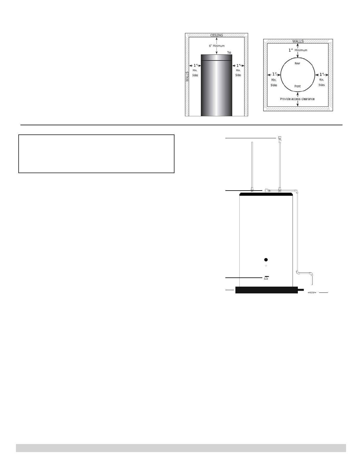
Minimum Clearance from Combustible Surfaces:
Bottom -------------------------------- 0”
Left, Right, Rear Sides --------------- 1”
Front ---------------------------------- 1”
Top ------------------------------------ 6”
Minimum Clearance for Service:
Bottom -------------------------------- 0”
Left, Right, Rear Sides --------------- 3”
Front ---------------------------------- 30”
Top ------------------------------------ 6”
3.
Additional recommended components
A. Shut-off valves. Allows the isolation of the
storage tank from the boiler system during
service.
B. Unions. Allows for easy locating or removal.
C. Vacuum breaker. Protects the storage tank from
collapse if a hot tank is valved off to service other
components in the system.
D. Thermal expansion tank. If the storage tank is
installed in a closed water supply system, such as
a system having a back ow preventer in the cold
water supply line, the installation of a thermal
expansion tank is required.
4.
Water Quality
Improper water quality will reduce the expected life of
the storage tank. Hard water, sediment, high or low
Ph, and high levels of chlorides in the domestic water
should be avoided. High or low Ph and/or high chloride
concentrations will cause corrosion and eventually fail. A
lter is strongly recommended where sediment is present
in the water. A water softening system is recommended
for areas with hard water.
In an area where the water quality is not known, a water
quality test should be performed.
WARNING:
Do not operate storage tanks in areas where the
Ph is above 8.0 or below 6.0, and/or with chloride
concentrations greater than 80 parts per million (ppm).
ECR’s standard warranty does not cover problems caused
by improper water Ph or excessive levels of chlorides.
1”
1”
1”
1”
1”
Front View Top View
Vacuum Relief
Temperature and
Pressure Relief Valve
Drain Pan
Drain Valve
Drain
5.
Piping
A. Drain the domestic water system.
Shut off the cold water supply at the main shutoff
valve.
Open one or more faucets to relieve the pressure.
Open the system drain, leaving the faucets open.
B. Position the storage tank in the nal location.
C. Connect the cold water supply piping.
Install piping on to cold inlet connection. Connect
to cold water supply connection using a union, a
heat trap, a shut-off valve, an expansion tank
(where required), a back ow preventer (where
required).
"The storage tank should be installed as close to the
boiler as is practical for easy access for service. The
unit is designed for installation on combustible ooring
and in alcoves, closets, etc."
9
D. Connect the domestic hot water piping.
Install piping on to hot water supply connection using a union, a heat trap, a vacuum breaker, and a shut-off
valve.
Pipe the relief valve discharge so that the discharge from the valve will exit only within 6 inches above, or at any
distance below, the structural oor, and cannot contact any live electrical part. The discharge opening must not be
blocked or reduced in size under any circumstances.
E. Fill the storage tank tank.
Open all faucets to allow air to purge from the tank and piping. Remove screens on faucets.
Open domestic hot water shut-off valve.
Open cold water inlet shut-off valve.
Purge all of the air from the domestic water system. Allow water to run so the tank is completely purged of any debris.
Run the water long enough to change at least ve tank volume changes. Close all faucets. Reinstall all of the screens in
the faucets.
Check the system for leaks. Repair as required.
IV. Electrical
1.
Install electric wiring and grounding in accordance with the National Electrical code and local regulations.
2.
All storage tanks are supplied with a thermostat.
V. Operation
Startup
After the storage tank has been plumbed and wired, and the sytem is purged of air, the storage tank is ready to be
started.
1.
The tank thermostat is factory pre-set to 125 degrees F and will call for heat if the water in the tank is lower than
125.
2.
On a call for heat, the tank thermostat contacts close to start the storage tank zone circulator and the heat source.
3.
After the tank has reached the temperature setting, the tank thermostat opens and de-energizes the circulator and
the heat source.
Temperature Adjustment
The tank aquastat controls the maximum water temperature in the storage tank. If it is set too high, the resulting hot
water can cause painful scalding with possible serious and permanent injury. The temperature at which this occurs varies
with a person’s age, and the length of time in contact with the hot water. The slower response time of infants, older, or
handicapped people increase the hazard for them.
It is recommended that the aquastat be set for the lowest possible temperature that satises your needs. This will also
provide you with the lowest energy consumption and cost.
Check the water temperature at a hot water faucet soon after the tank aquastat has satised, and the circulator and the
boiler have turned off. Adjust as needed.
Lowering the aquastat setting will not have an immediate effect on the water temperature because the stored water
will have to be used and the aquastat must go through the cycle of heating cold water and satisfying at the new, lower
temperature. Additional temperature checks should follow the completion of a heating cycle. Further adjustments may be
required after you have used the storage tank
VI. Maintenance
The storage tank is intended to provide many years of reliable service. Components, such as thermostats and relief
valves, may be subject to failures that require service. Failure to use the correct procedures or parts can result in unsafe
operation.
The owner should arrange to have the following inspections and simple maintenance procedures done at the suggested
frequencies.
1.
Water Piping (Annual)
Check all piping for signs of leakage at the joints, unions and shut-off valves. Repair as required.
2.
Temperature and Pressure Relief Valve (Annual)
10
The temperature and pressure relief valve should be checked to ensure that it is in operating condition. To
check the relief valve, lift the lever at the end of the valve several times. The valve should seat properly and
operate freely. If water does not ow, remove and inspect for obstructions or corrosion. Replace with a new
valve of the recommended capacity as necessary. Do not attempt to repair the valve, as this could result in
improper operation and a tank explosion. In areas with poor water conditions, it may be necessary to inspect
the temperature and pressure relief valve more often than once a year.
Before manually operating the valve, make sure that a drain line has been attached to the valve to direct the dis-
charge to an open drain. Failure to take this precaution could mean contact with extremely hot water discharging
from the valve during this checking operation.
If the temperature and pressure relief valve on the heater discharges periodically or continuously, it may be due
to thermal expansion of water in a closed water supply system, or it may be due to a faulty relief valve. Thermal
expansion is the normal response of water when it is heated. In a closed system, thermal expansion will cause the
system pressure to build until the relief valve actuation pressure is equaled. Then the relief valve will open, allow-
ing some water to escape, slightly lowering the pressure. Contact your water supplier or local plumbing inspector
on how to control this situation.
3.
Sediment (Annual except where harsh water quality may require more frequent service)
Depending on water conditions, a varying amount of sediment may collect in the tank. Repeated ushing usu-
ally clears such material. As a preventive measure, water should be drawn from the drain valve until it runs
clear and the installation of a water lter should be considered.
4.
Inspect Anode (annual)
The purpose of the magnesium anode is to reduce the damaging effects of aggressive water on the water
heater. Aggressive water will cause the anode(s) to erode. The anode(s) must be inspected at least annually
to determine whether a new anode should be installed. Use anode replacement parts supplied by ECR only.
ECR anodes are 1-1/4 NPT and are made with magnesium, brass, and stainless steel. There is no steel in a
ECR anode. Severe or rapid deterioration of the anode indicates very aggressive water. If this occurs, have the
water tested to verify whether it is within the limits outlined on page 3. Failure to inspect the anode regularly
and replace if necessary could result in damage to the water heater. If this unit is installed and maintained ac-
cording to the instructions and conditions in this manual, this product will last for a long time.
1.
Close domestic water isolation valves.
2.
Drain the water heater completely and allow it to cool off.
3.
Remove the anode cover on the front of the unit. See gures on pages 5. The temperature control can be
turned to the side to allow easier access.
4.
After the water heater has drained and cooled, remove the anode using a 1¾” 6-point socket and a
breaker bar.
5.
Inspect the anode and replace if needed. The anode should be replaced when more than 6” of core wire is
exposed. The anode should be replaced with a ECR supplied anode only. See above. The brass hex on the
anode is 1¼ NPT and installs into a 1¼ stainless half coupling on the shell of the tank. This part will need
to be properly Teon taped and coated with a quality Teon based pipe sealant.
6.
Replace the inspection cover.
7.
Rell the water heater, and restore to operation.
8.
Verify operation of the water heater.
NOTICE
11
Hot Water Booster/Storage Tanks
Description Part Number
1 Aquastat Well, Stainless Steel 240009522
2 Aquastat 240009521
3 Drain Valve, 3/4" Brass 240012194
4 Anode Rod 240010929
Replacement Parts
12
13
14
15
H
2
O
All specifications subject to change without notice.
©2020 ECR International, Inc.
ECR International Inc. 2201 Dwyer Avenue, Utica, NY 13501
Tel. 800 253 7900
www.ecrinternational.com
  • Page 1 1
  • Page 2 2
  • Page 3 3
  • Page 4 4
  • Page 5 5
  • Page 6 6
  • Page 7 7
  • Page 8 8
  • Page 9 9
  • Page 10 10
  • Page 11 11
  • Page 12 12
  • Page 13 13
  • Page 14 14
  • Page 15 15
  • Page 16 16

Dunkirk H2OST60 Installation, Operation & Maintenance Manual

Type
Installation, Operation & Maintenance Manual

Ask a question and I''ll find the answer in the document

Finding information in a document is now easier with AI