SERVICE
1. Check the fuel supply, electrical wiring, fuses, and make sure the temperature control is
calling for heat.
2. If the motor runs but there is no flame, remove the electrode assembly, clean, readjust, and
check the porcelain for cracks. Replace if necessary. Check the ignitor to see if it is produc-
i
ng a spark. (
U
se extreme caution—the ignitor has 14,000 volt output.
)
Make sure the
coupling between the motor and pump shaft is not slipping. Check the set screw on the
blower wheel for tightness. Clean or replace the nozzle with the correct size and spray
angle.
3. Bleed the pump and check for clear, air-free oil. If oil is milky or frothy, check the line for
air leaks at fittings. Tighten all fittings again. Check filter gaskets and make sure the car-
tridge is clean.
4. If the burner motor fails to start, reset the control and check for voltage on the burner lead.
If no voltage, replace control. If there is power to the motor connect a pig tail and 100 watt
bulb to the capacitor leads. If the motor starts, replace the capacitor. If not, check for ther-
mal lock out.
Note: The BCS burner is equipped with a split capacitor motor containing an
automatic reset thermal cut-out. If the motor cuts out because of overheating, it will reset
when the motor cools. Make certain that air can flow freely around burner. If motor locks
out repeatedly, check capacitor and the fuel pump turning torque before replacing motor.
5. If the burner ignites, runs for a short time (10–20 seconds), and then goes out on safety,
replace the flame detector. If the burner still runs only a short time, replace the control.
6. If you smell oil or combustion products, remove and clean the electrode assembly, readjust
combustion settings, and insure that the joints on the flue connections are sealed (see “Ex-
huast Vent” and “Fresh Air Intake Vent” installation, page 6).
7. The internal high limit located in the thermostat will break the circuit to the burner if
water overheating occurs. When this happens, the burner will not go into post purge or
may stop post purge prematurely. Replace the thermostat, if necessary.
If any other service problems arise, you may obtain more information by contacting your
installer or nearest Bock distributor; or write, call, or fax:
Bock Water Heaters, Inc. • 110 South Dickinson Street • Madison, WI 53703
Telephone 608-257-2225 • Fax 608-257-5304
LIMITED WARRANTY
This warranty covers “Bock” water heater models 32E-BCS, 40E-BCS, 51E-BCS, 120E-BCS and
190E-BCS. Bock Water Heaters, a division of Bock Corporation—a Wisconsin corporation—at
110 S. Dickinson Str
eet, Madison, W
isconsin 53703 (“Company”), warrants to the owner, the
tank of this water heater will not leak due to defective materials or workmanship for FIVE (5)
years from the date of original installation. If the water heater is installed in other than a
single family dwelling, this warranty is limited to THREE (3) years from the date of original
installation. The company also war
rants that no other part of this water heater will fail due to
a defect in material or workmanship for one (1) year.
Oil-Fired BCS Page 7Page 10 Oil-Fired BCS
CONNECT THE OIL LINE
Gravity System: The oil burner is normally equipped with a single-stage pump equipped
f
or one line (gravity) flow. Use
3
⁄8"
O.D. or larger soft copper tubing and attach with flared
fittings. DO NOT USE COMPRESSION FITTINGS. Install the shut off valve and oil filter in the
oil line. Follow instructions from the pump manufacturer (attached to pump).
Lift System: Run a two-line system (suction and return lines) for lifts over 8 feet. Install a
bypass plug if required according to the instructions attached to the pump. (Plug is in bag
with instruction sheet.) The burner may be ordered with a two-stage pump for high lifts or
longer runs.
WARNING!!! When you install the bypass plug you MUST run a two-line system!
For any horizontal run or lift that exceeds the maximum length specified in the chart below,
a booster pump must be used. Booster pumps may be obtained from Sun Tec Hydraulics, Rock-
ford, Illinois. Booster pumps must be installed as close to the oil supply tank as possible. Suc-
tion and return lines should be the same diameter and both go within 6" of the bottom of the
tank. The return line should stop slightly above the suction line. Use a minimum of fittings.
Make tubing bends with as large a radius as possible. DO NOT USE COMPRESSION FITTINGS.
Use caution in the final connection to the burner. Do not put strain on the fuel unit. Before
attaching tubing to the burner, form a coil in the tubing to minimize any vibration. Bury oil
lines in the floor for quiet operation, making sure there are NO CONNECTIONS OR FITTINGS
UNDER THE FLOOR.
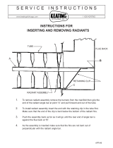
MAXIMUM LIFT AND HORIZONTAL RUN (Refer to pump manufacturer’s instructions)
Maximum Lift & Horizontal Run for Oil Units
Two-pipe System with Two-pipe System with
One-pipe System Single-Stage pump* Two-Stage pump**
Lift
Horizontal Run
Lift
3450 RPM
Lift
3450 RPM
3
⁄8" O.D. Tube
1
⁄2" O.D. Tube
3
⁄8" O.D. Tube
1
⁄2" O.D. Tube
3
⁄8" O.D. Tube
1
⁄2" O.D. Tube
0' 65' 100' 0' 84' 100' 0' 93' 100'
4' 45' 100' 1' 78' 100' 2' 85' 100'
7' 31' 100' 2' 73' 100' 4' 77' 100'
8' 16' 64' 3' 68' 100' 6' 69' 100'
Inlet vacuum must not exceed 6 inHG 4' 63' 100' 8' 60' 100'
on a one-pipe system
5' 57' 100' 10' 52' 100'
6'
52' 100' 12' 44' 100'
7' 47' 100' 14' 36' 100'
8' 42'
100' 16' 27' 100'
9' 36'
100'
18'
— 76'
10' 31' 100' *Suntec A Series pumps
11'
26'
100' **Suntec B Series pumps
12' 21' 83' Inlet vacuum must not exceed 6 inHG
13' — 62'
on a one-pipe system. On a two-pipe
14' — 41'
system, inlet vacuum must be less than
12 inHG for “A” model pumps and
17 inHG for “B” model pumps.