Page is loading ...

Q90 125-200 GAS-FIRED DIRECT VENT
CONDENSING HOT WATER BOILER
P/N 240004826D, Rev. 1.3 [01/06]
An ISO 9001-2000 Certified Company
DUNKIRK BOILERS
85 Middle Rd.
Dunkirk, NY 14048
www.dunkirk.com
INSTALLATION MANUAL AND OPERATING INSTRUCTIONS

2
! !
! !
! !
Q90 125-200 CAST ALUMINUM BOILER
INSTALLATION MANUAL AND OPERATING INSTRUCTIONS
P/N# 240004826D, Rev. 1.3 [01/06] • Printed in USA • Made In USA
TABLE OF CONTENTS
I. Introduction ........................................................ 2
II. Safety Symbols ................................................ 2
III. Rules For Safe Installation and Operation .........3
IV. Boiler Ratings and Capacities ......................... 4
V. Before Installing The Boiler .............................. 5
VI. Placing The Boiler ........................................... 9
VII. Near Boiler Piping .......................................... 9
VIII. Combustion Air and Vent Pipe .................... 11
IX. Gas Supply Piping ........................................ 13
X. Electrical Wiring ............................................. 15
XI. Controls and Accessories ............................. 17
XII. Startup ......................................................... 19
XIII. Checkout Procedures and Adjustments ........23
XIV. Maintenance and Cleaning ......................... 26
XV. Detailed Sequence of Operation .................. 28
XVI. Troubleshooting .......................................... 33
XVII. Installation and Checkout Certificate ......... 40
KEEP THIS MANUAL NEAR BOILER AND
RETAIN FOR FUTURE REFERENCE.
I. INTRODUCTION
This appliance is a gas-fired direct vent cast
aluminum hot water boiler. A revolutionary cast
aluminum heat exchanger means better heat
transfer and thermal storage than similarly sized
cast iron boilers, which results in higher efficiency.
The heating system water absorbs large amounts
of heat from the cast aluminum heat exchanger,
cooling the flue gases and causing condensation.
Sealed combustion, premix gas burner, and low
flame temperature means drastically reduced CO
and NOx emissions, which contribute to a cleaner
and healthier environment.
This appliance, unlike normal residential atmospheric
and induced draft units, takes its combustion air
directly from the outdoors (sealed combustion) and
does not compete with building occupants for fresh
air. Sealed combustion (also known as “direct vent”)
is the safest and best way to obtain plenty of clean
combustion air. The forced draft fan draws in the
outside combustion air to mix with gas, which flows
into the pre-mix burner and combusts. The fan then
forces the resulting flue gases from the boiler unit
and provides a positive removal of the flue gases
from the building through inexpensive and readily
available PVC and CPVC vent pipes.
II. SAFETY SYMBOLS
The following defined symbols are used throughout
this manual to notify the reader of potential hazards
of varying risk levels.
DANGER
Indicates an imminently hazardous situation
which, if not avoided, WILL result in death or
serious injury.
WARNING
Indicates a potentially hazardous situation
which, if not avoided, COULD result in death
or serious injury.
CAUTION
Indicates a potential hazardous situation
which, if not avoided, MAY result in minor or
moderate injury. It may also be used to alert
against unsafe practices.
IMPORTANT: Read the following instructions
COMPLETELY before installing!!

3
! !
III. RULES FOR SAFE INSTALLATION AND OPERATION
WARNING
This appliance has been equipped for residential installations. If used for commercial applications,
any and all additional code requirements must be adhered to for installation. This may require
additional controls, including but not limited to a manual reset low water cut off, a manual reset
high temperature limit, and wiring and/or piping modifications.
The manufacturer is not responsible for any field installation changes made to a boiler installation
WHICH ARE NOT DESCRIBED OR ACKNOWLEDGED IN THIS MANUAL
.
IMPORTANT: Failure to follow these instructions
could cause a malfunction of the boiler and result
in death, serious bodily injury, and/or property
damage.
For assistance or additional information, consult
a qualified installer, service agency, or the gas
supplier.
1. Check all applicable state and local building
codes and utility company requirements before
installation. This installation must conform with
these requirements in their entirety. In the absence
of these codes, use NFPA installation codes and
good industry practice.
2. Before servicing the boiler, allow it to cool.
Always shut off any electricity and gas supply
connected to the boiler prior to servicing.
3. Inspect gas line for leaks.
4. Be certain gas input rate is correct. Overfiring
may result in early failure of the boiler components.
This may cause dangerous operation. Underfiring
may result in too much air for the pre-mix burner
causing poor or loss of combustion.
5. Never vent the products of combustion from
this boiler to an enclosed space. Always vent to
the outdoors. Never vent to another room or to
inside a building.
6. Be sure there is adequate outdoor air supply
to boiler for complete combustion.
7. Follow a regular service and maintenance
schedule for efficient and safe operation.
8. Keep boiler area clean of debris and free of
combustible and flammable materials.
9. Proper through-the-wall or through-the-roof
combustion venting shall be in accordance with the
materials and methods described in this manual.
Installation must comply with local codes.
10. This boiler and related hot water heating
systems are not do-it-yourself items. They must be
installed and serviced by qualified professionals.

4
TABLE 2 - NATURAL GAS
Nominal Input
200,000 175,000 150,000 125,000
Vent Lengths Vent Lengths Vent Lengths Vent Lengths
Altitude Min Max Min Max Min Max Min Max
0 200,000 200,000 175,000 175,000 150,000 150,000 125,000 125,000
1,000 197,000 196,500 172,400 172,200 147,800 147,400 123,500 123,000
2,000 194,000 193,000 169,800 169,400 145,600 144,800 122,000 121,000
3,000 191,000 189,500 167,200 166,600 143,400 142,200 120,500 119,000
4,000 188,000 186,000 164,600 163,800 141,200 139,600 119,000 117,000
5,000 185,000 182,500 162,000 161,000 139,000 137,000 117,500 115,000
6,000 182,000 179,000 159,400 158,200 136,800 134,400 116,000 113,000
7,000 179,000 175,500 156,800 155,400 134,600 131,800 114,500 111,000
8,000 176,000 172,000 154,200 152,600 132,400 129,200 113,000 109,000
9,000 173,000 168,500 151,600 149,800 130,200 126,600 111,500 107,000
10,000 170,000 165,000 149,000 147,000 128,000 124,000 110,000 105,000
TABLE 3 - LP GAS
Nominal Input
200,000 175,000 150,000 125,000
Vent Lengths Vent Lengths Vent Lengths Vent Lengths
Altitude Min Max Min Max Min Max Min Max
0 200,000 200,000 175,000 175,000 150,000 150,000 125,000 125,000
1,000 195,900 195,750 171,900 171,200 146,900 146,700 123,050 122,250
2,000 191,800 191,500 168,800 167,400 143,800 143,400 121,100 119,500
3,000 187,700 187,250 165,700 163,600 140,700 140,100 119,150 116,750
4,000 183,600 183,000 162,600 159,800 137,600 136,800 117,200 114,000
5,000 179,500 178,750 159,500 156,000 134,500 133,500 115,250 111,250
6,000 175,400 174,500 156,400 152,200 131,400 130,200 113,300 108,500
7,000 171,300 170,250 153,300 148,400 128,300 126,900 111,350 105,750
8,000 167,200 166,000 150,200 144,600 125,200 123,600 109,400 103,000
9,000 163,100 161,750 147,100 140,800 122,100 120,300 107,450 100,250
10,000 159,000 157,500 144,000 137,000 119,000 117,000 105,500 97,500
IV. BOILER RATINGS & CAPACITIES
Ratings shown are for sea level applications. The boiler automatically derates input as altitude increases.
No alterations to boiler are required for altitudes above sea level.
TABLE 1 - SEA LEVEL RATINGS (NATURAL AND PROPANE GASES)
Model
Input
(MBH)
(1)
Heating Capacity
(MBH)
(1)(2)
Net I=B=R Rating
(MBH)
(1)
Shipping
Weight (lbs.)
AFUE
(2)
Flue Diameter
125 125 112.5 98 284 90 2” CPVC & 3” PVC
150 150 135 117 284 90 2” CPVC & 3” PVC
175 175 157.5 137 284 90 2” CPVC & 3” PVC
200 200 180 157 284 90 2” CPVC & 3” PVC
(1)
1 MBH = 1,000 Btuh (British Thermal Units Per Hour)
(2)
AFUE (Annual Fuel Utilization Efficiency) and Heating Capacity is based on Department of Energy test procedure.

5
These low pressure gas-fired hot water boilers are design certified by CSA International, for use with
natural and propane gases. The boilers are constructed and hydrostatically tested for a maximum work-
ing pressure of 50 psig (pounds per square inch gauge) in accordance with A.S.M.E. (American Society
of Mechanical Engineers) Boiler and Pressure Vessel Code, Section IV Standards for heating boilers.
The Boilers are certified in accordance with ANSI (American National Standards Institute) Z21.13
standards as gas-fired, direct vent, condensing, hot water boilers.
The Heating Capacity indicates the amount of heat available after subtracting the losses up the stack.
Most of this heat is available to heat water. A small portion is heat loss from the jacket and surfaces of
the boiler, and it is assumed that this heat stays in the structure. The Net I=B=R Rating represents the
portion of the remaining heat that can be applied to heat the radiation or terminal units (i.e. finned tube
baseboard, cast iron radiators, radiant floor, etc.). The difference between the Heating Capacity and the
Net I=B=R Rating, called the piping and pickup allowance, establishes a reserve for heating the volume
of water in the system and offsetting heat losses from the piping. The Net I=B=R Ratings shown are
based on a piping and pickup factor of 1.15 in accordance with the I=B=R Standard as published by the
Hydronics Institute. The Net I=B=R Rating of the boiler selected should be greater than or equal to the
calculated peak heating load (heat loss) for the building or area(s) served by the boiler and associated hot
water heating systems. The manufacturer should be consulted before selecting a boiler for installations
having unusual piping and pickup requirements.
V. BEFORE INSTALLING THE BOILER
Complete all of the following prior to installing the boiler.
CODES
This boiler product is a gas-fired, direct vent, con-
densing boiler and must be installed in accordance
with all applicable federal, state and local building
codes including, but not limited to the following:
United States - Installation shall conform
with National Fuel Gas Code (NFPA-54/ANSI
Z223.1 - latest revision)
Canada - Installation shall be in accordance
with CSA-B149.1 and .2 installation codes.
Where required by the authority having jurisdiction,
the installation must conform to the American Soci
-
ety of Mechanical Engineers Safety Code for Con-
trols and Safety Devices for Automatically Fired
Boilers, No.CSD-1.
The installation must conform to the requirements
of the authority having jurisdiction or, in the ab
-
sence of such requirements, to the National Fuel
Gas Code, ANSI Z223.1 - latest revision.
Installers - Follow local regulations with re-
spect to installation of CO (Carbon Monox-
ide) Detectors. Follow maintenance recom-
mendations in this manual.
BOILER SIZING
• Check to be sure you have selected the boiler
with the proper capacity before continuing the in-
stallation. The I=B=R Rating of the boiler selected
should be greater than or equal to the calculated
peak heating load (heat loss) for the building or
area(s) served by the boiler and associated hot
water heating systems. See Section IV, “Boiler
Ratings and Capacities,” for more information.
• Heat loss calculations should be based on
approved industry methods.
CONSIDERATIONS FOR BOILER LOCATION
Before selecting a location for the boiler, the follow-
ing should be considered. Each boiler considered
for installation must be:
• Supplied with the correct type of gas (natural
gas or propane).
• Connected to a suitable combustion air intake pip
-
ing system to supply the correct amounts of fresh
(outdoor) air for combustion (max. length 60’).
• Connected to a suitable venting system to re
-
move the hazardous products of gas combus-
tion (max. length 60’).

6
• Connected to a suitable hot water heating
system.
• Supplied with a suitable electrical supply for
all boiler motors and controls.
• Connected to a properly located thermostat
or operating control. (not included with boiler)
• Placed on level surface (must NOT be in
-
stalled on carpeting)
• Condensate drain line must be pitched down
to floor drain or external condensate pump with
reservoir at ¼”per foot (wood frame or blocks
may be used to raise boiler).
LOCATING THE BOILER
1. Select a location which is level, central to the
piping systems served and as close to the vent
and air intake terminals as possible.
2. Accessibility clearances, if more stringent (i.e.
larger clearances) than required fire protection
clearances, must be used for the boiler installa
-
tion. Accessibility clearances may be achieved
with the use of removable walls or partitions.
3. The boiler is approved for installation in clos
-
ets and on combustible floors. This boiler shall
NOT be installed on carpeting.
4. The clearances shown in Table 4 indicate re
-
quired clearances per CSA listing. A min. 1” clear-
ance must be maintained between combustible
construction and each of the right, top and back
surfaces of the boiler. A min. 8” clearance is re
-
quired on the left side, to allow room for the inlet
air pipe. An 18” clearance must be maintained at
the front where passage is required for cleaning or
servicing, inspection or replacement of any parts
that normally may require such attention. Allow at
least 24” at the front and left side and 8” at the top
for servicing. No combustible clearances are re
-
quired to venting or combustion air intake piping.
5. Equipment shall be installed in a location
which facilitates the operation of venting and
combustion air intake piping systems as de
-
scribed in this manual.
6. Advise owner of boiler to keep venting and
combustion air intake passages free of obstruc
-
tions. Both the venting and combustion air intake
piping systems connected to the outdoors must
permit flow through the piping systems without
restrictions for the boiler to operate.
7. The boiler shall be installed such that the
automatic gas ignition system components are
protected from water (dripping, spraying, rain,
etc.) during operation and service (circulator re
-
placement, control replacement, etc.).
8. The boiler must be located where ambient
temperatures (minimum possible room temper
-
atures where boiler is installed assuming boiler
is not in operation and therefore contributes no
heat to the space) are always at or above 32°F
to prevent freezing of liquid condensate.
COMBUSTION AIR/VENT PIPE REQUIREMENTS
This boiler requires a dedicated direct vent system.
In a direct vent system, all air for combustion is
taken directly from outside atmosphere, and all flue
products are discharged to outside atmosphere.
Combustion air and vent pipe connections must
terminate together in the same atmospheric pres
-
sure zone, either through the roof or sidewall (roof
termination preferred). See Figures 1 and 2 for re
-
quired clearances.
TABLE 4 - BOILER CLEARANCES
Unit
Combustible
Clearance
Accessibility, Clean-
ing, and Servicing
Top 1” 8”
Left Side 8” 24”
Right Side 1” -
Base 1” -
Front 0” 24”
Back 1” -
Intake/Vent
Piping
0” -
Near Boiler Hot
Water Piping
1” -
All distances measured from the cabinet of the boiler.
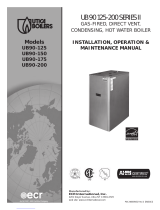
8" MINIMUM
VERTICAL SEPARATION
BETWEEN COMBUSTION
AIR INTAKE AND VENT
MAINTAIN 12" MINIMUM
CLEARANCE ABOVE HIGHEST
ANTICIPATED SNOW LEVEL
3'' MAXIMUM
SEPARATION
15'' MAXIMUM
COMBUSTION
AIR
12''
MIMIMUM
ROOF VENT/INTAKE TERMINATIONS
Figure 1

7
! !
If the concentric vent termination is being used, re-
fer to Figure 3 for proper setup.
CAUTION
Keep boiler area clean of debris and free of
flammable and combustible materials, vapors,
and liquids.
! !
WARNING
FAILURE TO FOLLOW THESE WARNINGS
COULD RESULT IN FIRE, PROPERTY
DAMAGE, PERSONAL INJURY, OR DEATH.
When vent pipe is exposed to temperatures
below freezing, such as when it passes through
an unheated space or when a chimney is used
as a chaseway, vent pipe must be insulated
with 1/2”Armaflex or equivalent. In extremely
cold climate areas, use 3/4”Armaflex or
equivalent.
Combustion air must be clean outdoor air.
Combustion air must not be taken from inside
the structure because that air is frequently
contaminated by halogens, which include
fluorides, chlorides, phosphates, bromides
and iodides. These elements are found in
aerosols, detergents, bleaches, cleaning
solvents, salts, air fresheners, paints,
adhesives, and other household products.
Locate combustion air inlet as far away as
possible from swimming pool and swimming
pool pump house. All combustion air and
vent pipes must be airtight and watertight.
Combustion air and vent piping must also
terminate exactly as shown in Figures 1-2. If
a concentric vent termination is being used,
refer to Figures 3-5 for proper setup.
Vent connections serving appliances vented
by natural draft shall not be connected into any
portion of mechanical draft systems operating
under positive pressure.
Solvent cements are combustible. Keep away
from heat, sparks, or open flame. Use only in
well ventilated areas. Avoid breathing in vapor
or allowing contact with skin or eyes.
CONCENTRIC VENT
Figure 4
SIDEWALL VENT/INTAKE TERMINATIONS
Figure 2
OVERHANG
12" MINIMUM
90°
VENT
12" SEPARATION
BETWEEN BOTTOM OF
COMBUSTION AIR INTAKE
AND BOTTOM OF VENT
MAINTAIN 12" MINIMUM
CLEARANCE ABOVE HIGHEST
ANTICIPATED SNOW LEVEL OR
GRADE
3"
MAXIMUM
SEPARATION
18"
MAXIMUM
15"
MAXIMUM
LESS THAN 12" CLEARANCE
12"
MINIMUM
12"
MINIMUM
12" OR MORE CLEARANCE
90°
BRACKET
VENT
18"
MAXIMUM
MAINTAIN 12" MINIMUM
CLEARANCE ABOVE HIGHEST
ANTICIPATED SNOW LEVEL OR
GRADE
12" SEPARATION
BETWEEN BOTTOM OF
COMBUSTION AIR INTAKE
AND BOTTOM OF VENT
12" MINIMUM
OVERHANG
3"
MAXIMUM
SEPARATION
12"
MINIMUM
12"
MINIMUM
ROOF
OVERHANG
12" MINIMUM
VENT
MAINTAIN 12" IN. CLEARANCE
ABOVE HIGHEST ANTICIPATED
SNOW LEVEL OR GRADE
COMBUSTION AIR
1" MAXIMUM
12" MINIMUM
CONCENTRIC VENT TERMINATIONS
Figure 3

8
CONCENTRIC VENT ROOF INSTALLATION
Figure 5
FOUNDATION REQUIREMENTS
Boiler must be placed on level surface. Boiler is
NOT to be installed on carpeting.
NOTES
1. If boiler is not level condensate drain lines will not function
properly. Adjustable feet are located on the boiler to make
up for minor surface irregularities or tilt.
2. Wood frame or blocks may be used to raise boiler to maintain
drain pitch or to be above external condensate pump reservoir.
REMOVAL OF EXISTING BOILER
FROM COMMON VENT SYSTEM
When an existing boiler is removed from a common
venting system, the common venting system is likely
to be too large for proper venting of the appliances
remaining connected to it. At the time of removal of
an existing boiler, the following steps shall be fol
-
lowed with each appliance remaining connected to
the common venting system placed in operation,
while the other appliances remaining connected to
the common venting system are not in operation.
1. Seal any unused openings in the common
venting system.
2. Visually inspect the venting system for proper
size and horizontal pitch and determine there is
no blockage or restriction, leakage, corrosion or
other deficiencies which could cause an unsafe
condition.
3. When it is practical, close all building doors
and windows and all doors between the space
in which the appliances remaining connected to
the common venting system are located and oth
-
er spaces of the building. Turn on clothes dryer
and any appliance not connected to the common
venting system. Turn on any exhaust fans, such
as range hoods and bathroom exhaust, so they
will operate at maximum speed. Do not operate
a summer exhaust fan. Close fire dampers.
4. Place in operation the appliance being in
-
spected. Follow the lighting instructions. Adjust
thermostat so appliances will operate continu
-
ously.
5. Test for spillage at the draft hood relief open-
ing after 5 minutes of main burner operation. Use
the flame of a match or candle, or the smoke
from a cigarette, cigar or pipe.
6. After it has been determined that each ap
-
pliance remaining connected to the common
venting system properly vents when tested as
outlined above, return doors, windows, exhaust
fans and any other gas-burning appliance to their
previous condition of use.
7. Any improper operation of the common vent
-
ing system should be corrected so the installation
conforms with the National Fuel Code, NFPA-
54/ANSI -Z223.1-latest revision, or section 5 of
CSA-B149 for Canadian standards. When resiz
-
ing any portion of the common venting system,
the common venting system should be resized to
approach the minimum size as determined using
the appropriate tables in part 11 in the National
Fuel Gas Code, NFPA-54/ANSI- Z223.1-latest
revision, or section 5 of CSA-B149 for Canadian
standards.

9
VI. PLACING THE BOILER
The boiler should be placed to provide the most
direct connections to the combustion air, vent and
system piping as possible.
Place crated boiler as close to selected location
as possible and uncrate boiler. The uncrated boiler
may be moved into position with an appliance dol
-
ly or 2-wheel hand truck. The dolly or hand truck
should be inserted under the right hand side of
the boiler. It is possible to slide the boiler for a short
distance on a smooth floor or surface.
NOTE: Refer to “Locating The Boiler” in Section V for re-
quired clearances for servicing and maintenance.
VII. NEAR BOILER PIPING
Determine required system fill pressure, system de-
sign temperature, and system water content. Boiler
contains 2.6 gallons (U.S.). Size expansion tank ac
-
cordingly. Consult expansion tank manufacturer for
proper sizing information. Connect properly sized
expansion tank (not furnished) as shown in Figure 6
for diaphragm type expansion tank. For diaphragm
type expansion tanks, adjust the tank air pressure
to match the system fill pressure. Install air vent
(furnished) as shown for diaphragm type expansion
tank system only. Install make-up water connec
-
tions as shown and per local codes. If a pressure
reducing valve is used, adjust to match the system
fill pressure. In connecting the cold make-up water
supply to the boiler, make sure that clean water sup
-
ply is available. When the water supply is from a well
or pump, a sand strainer should be installed at the
pump.
PRESSURE RELIEF VALVE /
TEMPERATURE PRESSURE GAUGE
The boiler is furnished with a relief valve and tem-
perature pressure gauge in the boiler parts bag. In
-
stall vent relief valve as shown in Figure 7. Provide
¾” piping from the relief valve to a local floor drain,
! !
CAUTION
Copper supply and return piping must NOT be in
-
stalled directly into aluminum boiler section castings
due to galvanic corrosion between dissimilar met
-
als. Iron or steel bushings or pipe nipples should
be used between copper system piping and boiler
to make final connection to boiler. Also, the use of
dielectric unions is acceptable. The packaged boiler
is furnished with iron piping in the front boiler sec
-
tion for the supply and return connections.
When the installation of the boiler is for a new heat
-
ing system, first install all of the radiation units (pan-
els, radiators, baseboard, or tubing) and the supply
and return mains. After all heating system piping and
components have been installed, make final con
-
nection of the system piping to the boiler.
A hot water boiler installed above radiation level must
be equipped with a low water cut off device (included
with boiler). A periodic inspection is necessary, as is
flushing of float type devices, per low water cut off
manufacturers specific instructions.
EXPANSION TANK AND MAKE-UP WATER
DIAPHRAGM TYPE EXPANSION TANK PIPING
Figure 6
RELIEF VALVE DISCHARGE PIPING
Figure 7

10
but leave an air gap between piping and drain.
No shutoff of any description shall be placed be
-
tween safety relief valve and the boiler, or on the
discharge pipes between such safety valve and the
atmosphere. Installation of the safety relief valve
shall conform to ANSI/ASME Boiler and Pressure
Vessel Code, Section IV. The manufacturer is not
responsible for any water damage.
SUPPLY AND RETURN LINES
The packaged boiler unit is set up to receive 1¼”
NPT supply and return piping from top access.
NOTE: The circulator pump and isolation valves are fur-
nished within a carton inside the boiler cabinet and can be
installed at the installer preferred location.
CONDENSATE DRAIN REQUIREMENTS
Condensate drain line to be pitched down to floor
drain at a minimum of ¼” per foot. An external con-
densate pump (not furnished) may be used if floor
drain is not available. The condensate pump must
be designed for flue gas condensate application.
Figure 9b
MULTIZONE BOILER PIPING
WITH ZONE VALVES
NOTE: When zoning with circulators, the furnished circulator pump
should be used as one of the zone pumps. Each stripped end of
the electrical wires for the circulator pump inside the junction box
should be taped or wire nutted to prevent short circuits. Unplug the
circulator pump wiring at the integrated boiler control.
MULTIZONE BOILER PIPING
WITH CIRCULATORS
Figure 9a
SINGLE ZONE BOILER PIPING
Figure 8
CONDENSATE DRAIN PIPING
Figure 10
1/2" UNTHREADED
PVC PIPING
2" LONG
1/2" UNTHREADED
PVC ELBOW
1/2" UNTHREADED
PVC PIPING
3 3/4" LONG
1/2" UNTHREADED
PVC ELBOW
1/2" UNTHREADED
PVC PIPING
1 3/8" LONG
1/2" ADAPTER
MALE NPT x SOCKET WELD
PVC PIPING
1 3/8" LONG
1/2" UNTREADED
PVC TEE
1/2" UNTHREADED
PVC PIPING
3 3/4" LONG
TO CONDENSATE DRAIN
(FIELD SUPPLIED)
TO EXHAUST VENT
(2" CPVC)
TO BOILER FLUE OUTLET
(2" CPVC)
2" NPT MALE PVC BUSHING
2" UNTHREADED MALE
x 2" NPT MALE
PVC BUSHING

11
NOTES
1. Condensate trap is to be built in the field per Figure 10
2. Wood frame or blocks may be used to raise the boiler
to maintain drain pitch or to be above external condensate
pump reservoir.
3. There is a 115 volt AC receptacle provided on the service
switch junction box which is located at the boiler right side, to
provide power for an external condensate pump (if needed).
CONDENSATE DRAIN PIPING
The condensate trap is to be field installed as previ-
ously shown in Figure 10. Provided are ½” PVC fit
-
tings for the condensate drain trap (assembled in the
field). The condensate drain is to be pitched down to
the floor drain at a minimum of ¼” per foot.
The ½” diameter schedule 40 PVC condensate
drain piping and pipe fittings must conform to ANSI
standards and ASTM D1785 or D2846. Schedule
40 PVC cement and primer must conform to ASTM
D2564 or F493. In Canada, use CSA or ULC certi
-
fied schedule 40 PVC drain pipe and cement.
A condensate pump with a reservoir (not furnished)
may be used to remove condensate to a drain line
(sanitary line) above boiler if a floor drain is not
available or is inaccessible.
VIII. COMBUSTION AIR AND VENT PIPE
CONNECTIONS AND TERMINATION
IMPORTANT: To prevent damage to the gas
burner and ensure proper operation of the unit,
installer must clean and remove all shavings from
the interior of all PVC pipe used on the air intake.
For boilers connected to gas vents or chimneys, vent
installations shall be in accordance with part 7, Venting
of Equipment, of the National Fuel Gas Code, ANSI
Z223.1-latest revision, CSA-B149.1 and B149.2, and
applicable provisions of the local building codes.
Provisions for combustion and ventilation air must
be in accordance with section 5.3, Air For Com
-
bustion and Ventilation, of the National Fuel Gas
Code, ANSI Z223.1-latest revision, CSA-B149.1
and B149.2, or applicable provisions of the local
building code.
These boilers require a dedicated direct vent sys
-
tem. All air for combustion is taken directly from
outdoors through the combustion air intake pipe.
All flue products are discharged to the outdoors
through the vent pipe.
1. See Figures 1-2 in Section V, “Combustion Air
and Vent Pipe Requirements,” for standard two-
pipe roof and sidewall terminations and Figures
3-5 (same section) for concentric vent termina
-
tions (roof termination is preferred). Combus
-
tion air and vent pipes must terminate together
in same atmospheric pressure zone as shown.
Construction through which vent and air intake
pipes may be installed is a minimum ¼” and max-
imum 24” thickness.
2. Combustion air and vent pipe fittings must con-
form to one of the following American National
Standards Institute (ANSI) and American Society
for Testing and Materials (ASTM) standards:
• D1784 (schedule-40 CPVC)
• D1785 (schedule-40 PVC)
FILLING CONDENSATE TRAP WITH WATER
ON INITIAL START UP THE CONDENSATE TRAP
MUST BE MANUALLY FILLED WITH WATER.
The following are the steps required to initially fill
the condensate trap for start up, these steps are
only required at the initial start up or if maintenance
requires draining of the condensate trap:
1. Pour about 1 cup of cold tap water into the
condensate trap vent.
2. Excess water should go through the conden
-
sate drain line. Verify proper operation of the drain
line (and external condensate pump if used).
CHILLED WATER PIPING
The boiler, when used in connection with a refrig-
eration system, must be installed so the chiller me
-
dium is piped in parallel with the boiler with appro
-
priate valves to prevent the chilled medium from
entering the boiler.
The boiler piping system of a hot water boiler con
-
nected to heating coils located in air handling units
where they may be exposed to refrigerated air cir
-
culation must be equipped with flow control valves
or other automatic means to prevent gravity circu
-
lation of the boiler water during the cooling cycle.

12
• D2665 (PVC-DWV)
• D2241 (SDR-21 and SDR-26 PVC)
• D2661 (ABS-DWV)
• F628 (schedule-40 ABS).
Pipe cement and primer must conform to ASTM
standards D2564 (PVC) or D2235 (ABS).
In Canada construct all combustion air and vent
pipes for this unit of CSA or ULC certified sched
-
ule-40 CPVC, schedule-40 PVC, PVC-DWV or
ABS-DWV pipe and pipe cement. SDR pipe is
NOT approved in Canada.
3. Combustion air and vent piping connections
on boiler are 2”, but must increase to 3”. Due to
potential for flue gas temperatures over 155°F,
the first 5 feet of vent pipe must be CPVC (fur
-
nished), the remaining vent pipe can be PVC.
If any elbows are employed within the first 2 ½’
feet of vent, they must be CPVC. Two 30” pieces
of 2” CPVC pipe and one 2” CPVC coupling are
furnished with the boiler. (Figure 11)
NOTE: The exhaust transition from 2” pipe to 3” pipe must
be made in a vertical run. (Transition pieces not included.)
The length of pipe is counted from the boiler jack-
et (air intake pipe) or from vent tee (vent pipe).
The first five feet of “Total Equivalent Length” of
vent pipe must be CPVC.
Reduce the maximum vent length 5 feet per
each additional elbow.
4. Combustion air and vent piping to be pitched
back to boiler at minimum ¼” per foot from intake
and vent terminals so that all moisture in com
-
bustion air and vent piping drains to boiler. Pipes
must be pitched continuously with no sags or low
spots where moisture can accumulate and block
the flow of air or flue gas. Combustion air and
vent pipes must be airtight and watertight.
5. Consideration for the following should be used
when determining an appropriate location for ter
-
mination of combustion air and vent piping:
• Comply with all clearances required as
stated in paragraph 6 (below)
• Termination should be positioned where
vent vapors will not damage plants/shrubs,
air conditioning equipment, or siding on the
house.
• Termination should be positioned so that
it will not be effected by wind eddy, air born
leaves, snow, or recirculated flue gases.
• Termination should be positioned where it
will not be subjected to potential damage by
foreign objects, such as stones, balls, etc.
• Termination should be positioned where
vent vapors are not objectionable.
• Put vent on a wall away from the prevailing
winter wind. Locate or guard the vent to pre-
vent accidental contact with people or pets.
• Terminate the vent above normal snow-
line. Avoid locations where snow may drift
and block the vent. Ice or snow may cause
the boiler to shut down if the vent becomes
obstructed.
• Under certain conditions, flue gas will con
-
dense, forming moisture, and may be corro
-
sive. In such cases, steps should be taken
to prevent building materials at the vent from
being damaged by exhaust of flue gas.
6. The venting system shall terminate at least 3
feet above any forced air inlet (except the boiler’s
combustion air inlet) within 10 feet. The venting
system shall terminate at least 12 inches from
any air opening into any building. The bottom
of the vent shall be located at least 12 inches
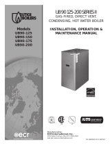
3 in. Pipe
Minimum Venting
3 in. Pipe
Maximum Venting
6 ft. in length plus
four (4) 90° elbows
60 ft. in length and up
to four (4) 90° elbows
COMBUSTION AIR AND VENT PIPING
Figure 11
5'
3 INC H INTAK E AND
E X HAUS T T E R MINAT IONS
E X HAUS T T E E
(F UR NIS HE D)
2˝ (50.8MM) C O MB US T ION AIR
IN T AK E P IP ING
2˝ (50.8MM) C P V C C O U P L ING
(F UR NIS HE D)
2˝ (50.8MM) C P V C VE NT P IP ING
(F UR NIS HE D & R E QUIR E D )
A04177
IN S T A LL F IE LD S UP P L IE D
2˝ B Y 3˝ T R AN S ITIO N IN
T HE VE R TIC AL P O S IT ION O NLY
NOT IN
HOR IZONAL
S E C T IO N

13
above grade. Termination of the vent shall be
not less than 7 feet above an adjacent public
walkway. The vent terminal shall not be installed
closer than 3 feet from the inside corner of an L
shaped structure. Termination of the vent should
be kept at least 3 feet away from vegetation.
The venting system shall terminate at least 4
feet horizontally from, and in no case above or
below electric meters, gas meters, regulators,
and relief equipment.
If multiple terminations are used, there must be
a minimum of 12 inches between the exhaust
of one termination and the air intake of the next
termination. See Figures 1-3 in Section E5 for il
-
lustrations.
NOTE: All field installed vent pipe must be 3”.
INSTALLATION
1. Attach combustion air intake piping to sup-
plied Fernco 2” coupling on CVI gas valve. At-
tach vent piping to furnished 2” CPVC vent tee
on draft inducer outlet.
NOTE: All pipe joints are to be water tight.
2. Working from the boiler to the outside, cut
pipe to required length(s).
3. Deburr inside and outside of pipe. Remove all
chips and shavings.
4. Chamfer outside edge of pipe for better distri
-
bution of primer and cement.
5. Clean and dry all surfaces to be joined.
6. Check dry fit of pipe and mark insertion depth
on pipe.
NOTE: It is recommended that all pipes be cut, prepared, and
pre-assembled before permanently cementing any joint.
7. After pipes have been cut and pre-assem-
bled, apply cement primer to pipe fitting socket
and end of pipe to insertion mark. Quickly apply
approved cement to end of pipe and fitting sock-
et (over primer). Apply cement in light, uniform
coat on the inside of socket to prevent buildup of
excess cement. Apply second coat.
8. While cement is still wet, insert pipe into sock
-
et with a ¼ turn twist. Be sure pipe is fully in
-
serted into fitting socket.
9. Wipe excess cement from joint. A continuous
bead of cement will be visible around perimeter
of a properly made joint.
10. Handle pipe joint carefully until cement sets.
11. Support combustion air and vent piping a mini
-
mum of every 5 feet using pre-formed metal hang
-
ing straps. Do not rigidly support pipes. Allow for
movement due to expansion and contraction.
NOTE: Rigid supports will cause excess noise in vent piping.
12. Slope combustion air and vent pipes toward
boiler a minimum of ¼” per linear foot with no
sags between hangers.
13. Use appropriate methods to seal open
-
ings where vent and combustion air pipes pass
through roof or side wall.
IX. GAS SUPPLY PIPING
CHECK GAS SUPPLY
The gas pipe to your boiler must be the correct size
for the length of run and for the total BTU per hour
input of all gas utilization equipment connected to
it. See Table 6 for proper size. Be sure your gas
TABLE 5 - GAS SUPPLY PRESSURE
Pressure Natural Gas Propane Gas
Minimum 4” w.c. 10” w.c.
Maximum 10” w.c. 14” w.c.
Please check line pressure while unit is running.
line complies with local codes and gas company
requirements.
The boiler and its individual shutoff valve must be
disconnected from the gas supply piping system
during any pressure testing of that system at test
pressures in excess of ½ psig (3.5kPa).
The boiler must be isolated from the gas supply pip
-
ing system by closing its individual manual shutoff
valve during any pressure testing of the gas supply
piping system at test pressures equal to or greater
than ½ psig (3.5kPa).

14
! !
GAS PIPING
Figure 12
TABLE 6 - NATURAL GAS PIPING SIZES
Pipe
Length
Pipe Capacity - BTU/Hr. Input
(1)
½” ¾” 1” 1¼”
20’ 92,000 190,000 350,000 625,000
40’ 63,000 130,000 245,000 445,000
60’ 50,000 105,000 195,000 365,000
TABLE 6 - PROPANE GAS PIPING SIZES
Pipe
Length
Pipe Capacity - BTU/Hr. Input
(1)
Copper Tubing
(2)
Iron Pipe
⅝” ¾” ½” ¾”
20’ 131,000 216,000 189,000 393,000
40’ 90,000 145,000 129,000 267,000
60’ 72,000 121,000 103,000 217,000
(1)
Includes Fittings
(2)
Outside Diameter
IMPORTANT: The length of pipe or tubing should
be measured from the gas meter or propane sec-
ond stage regulator.
CONNECTING THE GAS PIPING
Refer to Figure 12 for the general layout at the boil-
er. The gas line enters the boiler through the left
side panel.
The boiler is equipped with a ½” NPT connection on
the gas valve for supply piping and ½” NPT ball cock
for manual shut off. The following rules apply:
1. Use only those piping materials and joining
methods listed as acceptable by the authority
having jurisdiction, or in the absence of such
requirements, by the National Fuel Gas Code,
ANSI Z223.1- latest revision. In Canada, follow
the CAN/CGA B149.1 and .2 Installation Codes
for Gas Burning Appliances and Equipment.
2. Use pipe joint compound suitable for liquefied
petroleum gas on male threads only.
3. Use ground joint unions.
4. Install a sediment trap upstream of gas con
-
trols.
5. Use two pipe wrenches when making the con
-
nection to the gas valve to keep it from turning.
6. Install a manual shutoff valve in the vertical
pipe about 5 feet above floor outside the boiler
jacket.
7. Tighten all joints securely.
8. Propane gas connections should only be
made by a licensed propane installer.
9. Two stage regulation should be used by the
propane installer.
10. Propane gas piping should be checked out
by the propane installer.
11. It is recomended to use a ½” union suitable
for natural and propane gas after the ball cock to
facilitate service on the unit.
CHECKING THE GAS PIPING
After all connection have been made, check imme-
diately for leaks. Open the manual shutoff valve.
Test for leaks by applying soap suds (or a liquid
detergent) to each joint. Bubbles forming indicate
leak. CORRECT EVEN THE SMALLEST LEAK
AT ONCE.
WARNING
Never use a match or open flame to test for
leaks.

15
! !
! !
X. ELECTRICAL WIRING
WARNING
Turn off electrical power at fuse box before
making any line voltage connections. Follow
local electrical codes.
All electrical work must conform to local codes as
well as the National Electrical Code, ANSI/NFPA-
70, latest revision. In Canada, electrical wiring shall
comply with the Canadian Electrical Codes, CSA-
C22.1 and .2.
ELECTRIC POWER SUPPLY
Prior to making any line voltage connections, ser-
vice switch at boiler should be in the off position
and the power turned off at the fuse box.
Run a 120 volt circuit from a separate over current
protection device in the electrical service entrance
panel.
NOTE: Use copper conductors only.
This should be a 15 ampere circuit. A service switch
has been pre-wired and located on the exterior
boiler jacket. See Figure 13 for diagram showing
location of service switch junction box and power
supply connection points. Connect black (hot) lead
from the power supply to either of the unused brass
screws on the service switch. Connect the white
(neutral) lead from the power supply to the white
screw on the service switch. Connect the green
(ground) lead from the power supply to the ground
(green) screw on the service switch. The recepta-
cle on the service switch is always powered regard-
less of whether the switch is on or off, and could be
used as a power supply for an external condensate
pump if one is used.
The boiler, when installed, must be electrically
grounded in accordance with the requirements of
the authority having jurisdiction or, in the absence
of such requirements, with the National Electrical
Code, ANSI/NFPA-70, latest revision. In Canada,
electrical wiring shall comply with the Canadian
Electrical Codes, CSA-C22.1 and .2.
Run a 14 gauge or heavier copper wire from the
boiler to a grounded connection in the service pan
-
el or a properly driven and electrically grounded
ground rod.
INSTALLING THE THERMOSTAT
The thermostat location has an important effect on
the operation of your boiler system. BE SURE TO
FOLLOW THE INSTRUCTIONS INCLUDED WITH
YOUR THERMOSTAT.
Locate the thermostat about five feet above the
floor on an inside wall. It may be mounted directly
on the wall or on a vertical mounted outlet box. It
should be sensing average room temperature.
AVOID THE FOLLOWING:
Dead Spots - corners; alcoves; behind
doors
Cold Spots - concealed pipes or ducts;
stairwells - drafts; unheated rooms on the
other side of the wall
Hot Spots - concealed pipes; fireplaces; TVs
or radios; lamps; direct sunlight; kitchens
Set heat anticipator at 0.7 amps. Connect 24 volt
thermostat leads to the two (2) yellow wires located
in service switch junction box, located on outer jack
-
et of boiler. See Figure 12 for service switch junction
box and thermostat field wiring connections.
CONNECT CIRCULATOR PUMP WIRING
See Figure 14 for service switch junction box and
circulator pump field wiring connections. If the two
120 volt circulator wire terminals inside the junction
box are not used, please leave the two wire nuts to
prevent the short circuit.
CAUTION
Label all wires prior to disconnection when ser
-
vicing controls. Wiring errors can cause improp-
er and dangerous operation. VERIFY PROPER
OPERATION AFTER SERVICING.
•
•
•
Figure 13

16
SCHEMATIC WIRING CONNECTIONS
NOTE: If any of the original wire as supplied with this appliance must be replaced, it must be replaced with type 150°C Thermoplastic wire or its equivalent.
Figure 14
LADDER WIRING DIAGRAM

17
This section provides a brief description of the key
controls and accessories found in this boiler.
See Section XVII, “Troubleshooting,” in this instal
-
lation manual for detailed sequences of operation
and troubleshooting procedures. See the separate
-
ly provided “Repair Parts Manual” for locations of all
control components and accessories described.
INTEGRATED BOILER CONTROL (IBC)
The Integrated Boiler Control (IBC) is a micro-
processor based controller for high efficiency gas
boilers that monitors all safety controls and which
controls the operation of the combustion air blow
-
er, circulator pump, burner, and a combination hot
surface igniter/flame sensor. This controller is not
intended for use with a vent damper. This controller
is mounted on the control panel inside the boiler
and contains five diagnostic indicator lights.
GAS CONTROL VALVE
The electronic 24 volt gas control valve contains a
1:1 gas/air pressure regulator to control gas flow to
the main burner of the appliance, is suited for both
natural and LP gas, and is rated in accordance with
ANSI Z21.21 - latest revision and and CGA-6.5-M95.
HOT SURFACE IGNITER
The 120 volt hot surface igniter heats up to 1800°F
to initiate combustion of the gas in the burner. The
igniter is mounted next to the burner through the
gas/air mixer. The igniter also serves as a means
for proving the main burner flame by flame rectifica
-
tion. In the event of a lack of flame signal on three
consecutive trials for ignition, the IBC will lock out.
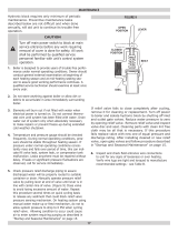
The “Valve” and “Flame” diagnostic indicator lamps
(see
Figure 16) will blink indicating the failure mode
as a lack of flame signal. The IBC is manually reset
from lockout by either removing and reestablishing
the thermostat’s call for heat, or by turning the ser
-
vice switch off, then back on.
HIGH LIMIT AQUASTAT CONTROL
The high limit aquastat control determines the maxi-
mum boiler water temperature and also provides a
means for protecting the boiler and heating system
from unsafe operating conditions which could dam
-
age the boiler. The aquastat is mounted in the ½” NPT
control well and ¾” x ½” bushing on the top of the front
boiler section at the hot water outlet. The aquastat is
tied in with the IBC and is factory set at 180°F water
temperature. The high limit setpoint is field adjustable
and may be set anywhere between 100°F and 200°F.
The field setpoint adjustment for each installation de
-
pends on heating system requirements. The aquastat
automatically resets when the boiler water tempera
-
ture drops 20°F below the setpoint value. This reset
value can be field adjusted within a range of 5-30°F.
NOTE: The maximum setpoint of the aquastat must not
exceed 200°F.
CASTING TEMPERATURE SAFETY SWITCH
In the event of lack of or loss of water in the boiler,
the casting temperature safety switch (230°F set-
point) installed on the top of the aluminum boiler
section behind the supply piping shuts off the boiler
by shutting off power to the IBC and causes the
power indicator light to go out. This fault requires
manual reset of the casting temperature safety
switch to restart the boiler. Verify that the boiler
is properly filled with water before resetting this
switch.
XI. CONTROLS AND ACCESSORIES
GAS VALVE
Figure 15
INDICATOR LIGHTS
Figure 16

18
! !
WARNING
Never run cold water into a hot, empty boiler.
DIFFERENTIAL PRESSURE SWITCHES
The diaphragm type differential pressure switches
are connected by vinyl tubing to the gas valve and
the air inlet connection on the negative side and the
sight glass adapter on the positive side. The pres
-
sure switches monitor air flow by sensing the differ-
ential pressure measured in inches of water (” w.c.).
The factory settings on these switches are 0.5” w.c.
on the normally open switch and 3.5” w.c. for the nor
-
mally closed switch. See Section XVI, “Detailed Se-
quence of Operation,” for details on the operation of
the differential pressure switches.
BLOWER
The blower provides a means for pushing combus-
tion air into and through the mixer, the burner, the flue
ways of the cast aluminum boiler section before being
discharged through the vent piping to the outdoors.
CIRCULATOR PUMP
Every forced hot water system requires at least one
circulating pump. The circulating pump imparts the
necessary energy to move the water through the
closed loop supply and return piping systems, ter
-
minal heating equipment (finned tube radiators, etc.)
and back through the boiler for reheating. To provide
the required hot water flow rates, the circulator pump
must be properly sized to overcome frictional losses
(usually measured in feet of water, also referred to
as “pump head loss”) of the supply and return piping
systems and boiler. The circulator pump is furnished
in a carton within the boiler cabinet. The circulator(s)
should always be located on the downstream (i.e.,
“pumping away”) side of the expansion tank.
DRAIN VALVE
The manual drain valve provides a means of draining
the water in the heating system, including the boiler
and hot water supply and return piping systems in
-
stalled above the drain valve. This drain valve is in-
stalled in the ¾” tapping at the bottom of the boiler.
Any piping installed below the elevation of this drain
valve will require additional drain valves to be in
-
stalled at low points in the piping systems in order to
drain the entire system.
A.S.M.E. RATED PRESSURE RELIEF VALVE
Each boiler must have a properly sized and installed
A.S.M.E. rated pressure relief valve. Water expands
as it is heated by the burner/boiler sections. If there
is no place for the water to expand its volume, (i.e., a
properly sized and functioning expansion tank) pres-
sure on the inside of the boiler and heating system
will increase. The furnished relief valve will automati
-
cally open at 30 psig pressure to relieve the strain
on the boiler and heating system from the increasing
pressure. The pressure relief valve discharge must
be piped with the same size as the valve discharge
opening to an open drain, tub or sink, or other suitable
drainage point not subject to freezing, in accordance
with A.S.M.E. specifications. Failure to provide the
pressure relief valve with piping as herein described
may cause water damage and/or serious bodily in
-
jury. The boiler manufacturer is not responsible for
any water damage or personal injury.
BLOCKED VENT SAFETY SHUTOFF
The boiler is equipped with a blocked vent safety
shutoff which shuts off the main burner gas in the
event that the airflow of combustion products through
the flue-way is reduced. In the event of a blocked
flue-way, enough air will not be available to support
combustion and the IBC will lock out due to loss of
adequate air flow. Pressure switches monitor air flow
by sensing differential pressure. The contacts are
normally open and close when the draft inducer is
running and causing the differential pressure at the
switch to exceed its setting. The closed switch proves
there is adequate air flow for combustion. The pres-
sure switch shuts off the main burner if the differential
pressure is inadequate due to a blocked vent pipe,
a blocked air intake, a blocked boiler section, or a
blocked air inducer. After 5 minutes of inadequate dif
-
ferential pressure, the IBC will lock out. The “Purge”
indicator lamp (see Figure 16) will blink, indicating
a failure to prove adequate combustion air flow or
flue gas flow. The IBC will automatically reset after
15 minutes or can be manually reset as noted in the
section titled “Hot Surface Igniter.” If the boiler cannot
be restored to normal operating condition by reset
-
ting the control, contact a qualified service agency to
check the heat exchanger flue-ways for blockage.
LOW WATER CUT OFF
This unit is equipped with a low water cut off control
that protects against dry firing. This control provides
burner cut off if there is an unsafe water loss, which
can result from a broken or leaking radiator, pipe, or
boiler. A water/glycol mixture up to 50% concentra
-
tion may be used with the low water cut off.
EXTERNAL CONDENSATE PUMP (OPTIONAL)
For installations where there is no floor drain or other
appropriate drainage available to receive conden-

19
XII. STARTUP
WATER TREATMENT AND
FREEZE PROTECTION
1. Consult local water treatment specialist for reco-
mendations if your water pH levels are below of 7.0
or hardness is above 7 grains hardness.
a. This boiler is designed for use in a closed
hydronic heating system ONLY!
b. Excessive feeding of fresh make-up water
to the boiler may lead to premature failure of
the boiler sections.
2. Use clean fresh tap water for initial fill and peri
-
odic make-up of boiler.
a. A sand filter must be used if fill and make-
up water from a well is to be used.
b. Consideration should be given to cleaning
the heating system, particularly in retrofit sit
-
uations where a new boiler is being installed
in an older piping system.
c. In older systems, obviously discolored,
murky, or dirty water, or a pH reading below
7, are indications that the system should be
cleaned.
d. A pH reading between 7 and 8 is preferred
when antifreese is not used in the system.
3. Antifreeze, if needed, must be of a type specifi
-
cally designed for use in closed hydronic heating
systems and be compatible with type 356 T6 alumi
-
num at operating temperatures between 20°F and
250°F.
a. Use of antifreeze must be in accordance
with local plumbing codes.
b. Pure glycol solutions are very corrosive,
therefore hydronic system antifreeze typi
-
cally contains corrosion inhibitors. Different
brands of hydronic system antifreeze contain
different types of corrosion inhibitors. Some
brands have corrosion inhibitors that break
down more rapidly or become ineffective at
higher temperatures when used with alumi
-
num. This could lead to premature failure of
the aluminum boiler. Consult the antifreeze
manufacturer on the compatibility of their
product with aluminum.
c. Follow the antifreeze manufacturer’s in
-
structions on determining proper ratio of an
-
tifreeze to water for the expected low tem
-
perature conditions, and for maintaining the
quality of the antifreeze solution from year to
year. Improperly maintained antifreeze solu
-
tions will gradually lose their ability to protect
the aluminum boiler from corrosion.
d. The recommended premixed antifreeze
solution is INTERCOOL NFP-50. This prod
-
uct is sold direct to distributors by the manu
-
facturer. Please contact Interstate Chemical
Company at 1-800-422-2436 or your distribu
-
tor for more information.
Use of an alternate manufacturer’s premix
antifreeze is acceptable if the product speci
-
fications are comparable with those of the
recommended premix antifreeze and the an
-
tifreeze is compatible with type 356 T6 alu
-
minum. Use of incompatible antifreeze could
damage the heat exchanger and will void the
product warranty.
The antifreeze must be maintained per the
specifications of the manufacturer. Failure to
do so will result in the warranty being voided.
Follow the antifreeze manufacturer’s instruc
-
tions on determining the proper ratio of an
-
tifreeze to water for the expected low tem
-
perature conditions and for maintaining the
antifreeze solution from year to year.
e. DO NOT USE AUTOMOTIVE ANTI-
FREEZE, as the type of corrosion inhibitors
used will coat the boiler’s heat transfer sur
-
sate from the boiler, an external float activated con-
densate pump with integral sump (supplied by oth-
ers) is required. The condensate pump can be piped
to a remote tie in point to a sanitary sewer system.
For this application, the boiler must be installed so
that proper pitch of piping to the external condensate
reservoir (sump) can be accomplished. Use wood
frame or blocks (not factory supplied) to raise boiler
as required for proper installation.

20
faces and greatly reduce capacity and effi-
ciency.
f. Use of antifreeze in any boiler will reduce
heating capacity by as much as 10-20% due
to differing heat transfer and pumping char-
acteristics. This must be taken into consid
-
eration when sizing the heating system,
pump(s) and expansion tank. Consult anti
-
freeze manufacturer’s literature for specific
information on reduced capacity.
g. Water content of the boiler is 2.6 gallons
(10 liters).
h. Antifreeze will raise the pH of the water in
a heating system to between 8.0 and 10.0.
This is due to the corrosion inhibitors in the
antifreeze.
FILLING BOILER WITH WATER AND
PURGING AIR FOR SYSTEMS WITH
DIAPHRAGM TYPE EXPANSION TANKS
Refer to the appropriate diagrams in Section VII,
“Near Boiler Piping,” for more information.
1. Close all zone service valves on the supply
and return piping. Open the feed valve and fill
boiler with water. Make sure air vent is open.
Hold relief valve open until water runs air free
for five seconds to rapidly bleed air from boiler,
then let the relief valve snap shut.
2. Open the zone service valve on the
supply
pipe for the first zone. Open the purge valve
on the first zone. Feed water will fill the zone,
pushing air out the purge valve. Close the purge
valve when the water runs air free. Close the
zone service valve.
3. Repeat step 2 for all remaining zones.
4. Open all service valves. Any air remaining
trapped in the return lines between the service
valves and the boiler will be pushed towards the
air vent when the boiler is placed in operation.
5. Inspect piping system. Repair any leaks im
-
mediately.
FILLING BOILER WITH WATER
AND PURGING AIR
FOR SYSTEMS WITH CONVENTIONAL
CLOSED TYPE EXPANSION TANKS
Refer to the appropriate diagrams in Section VII,
“Near Boiler Piping,” for more information.
1. Close all zone service valves on the supply
and return piping and close the expansion tank
service valve. Drain expansion tank. Open the
feed valve and fill boiler with water. Hold relief
valve open until water runs air free for five sec
-
onds to rapidly bleed air from boiler, then let the
relief valve snap shut.
2. Open the zone service valve on the
supply
pipe for the first zone. Open the purge valve
on the first zone. Feed water will fill the zone,
pushing air out the purge valve. Close the purge
valve when the water runs air free. Close the
zone service valve.
3. Repeat step 2 for all remaining zones.
4. Open the expansion tank service valve and
the tank vent. Fill the tank to the proper level
and close the tank vent. Remove the handle
from the expansion tank service valve so the
homeowner doesn’t accidentally close it.
5. Open all service valves. Any air remaining
trapped in the return lines between the service
valves and the boiler will be pushed towards the
expansion tank when the boiler is placed in op
-
eration.
6. Inspect piping system. Repair any leaks im
-
mediately.
NOTE: DO NOT use stop leak compounds. Leaks in
threaded connections in the aluminum boiler sections
must
be repaired immediately. Aluminum threads will not seal
themselves.
PLACING BOILER IN OPERATION
READ BEFORE OPERATING APPLIANCE
1. This appliance does not have a pilot. It is
equipped with an ignition device which automat
-
ically lights the burner. Do NOT try to light this
burner by hand.
/