Page is loading ...


OVERVl F POTENTIALHAZARDS
READTHISSAFETYINFORMATI N
Garage doors arelarge, heavy objectsthat move with the help of springs under high tension and electric motors. Since moving
objects, springs under tension, and electric motorscan cause injuries, your safety and the safety of others depend on the owner or
user of this system to read, understandand implementthe informationin this manual. Ifyou havequestionsor do NOT
understandthe informationpresented,contact The Genie Companyor an authorized Genie®Dealer.
The safety alert symboland following signalwords DANGER,WARNING, and CAUTIONare used throughout this manualto call
attentionto and identifydifferent levels of hazard and special instructions.
,& This isthe safety alert symbol. This symbol isplaced next to signalwords and messagesto help you identify
importantsafety information
Theword:
,& DANGERindicatesan imminently hazardoussituation which, if NOTavoided,will resultin death orserious injury.
,& WARNING indicatesa potentiallyhazardoussituation which, if NOT avoided, could result in death or serious injury.
CAUTION indicatesa potentially hazardoussituationwhich, if NOTavoided, may result in injuryor property damage.
Theword ,;0 is used to indicate importantstepsto be followed, importantconsiderations,or location of parts.
IMPORTANTSAFETYINSTRUCTIONS
READAND FOLLOWALL INSTRUCTIONS
SAVETHESEINSTRUCTIONS
POTENTIAL
HAZARD
MOVINGDOOR
ELECTRICAL
SHOCK
PREVENTION
Keep people clear of openingwhile door is moving.
Do NOTallow children to playwith the door operator.
Do NOToperate adoor that jams or one that hasa brokenspring.
Turn OFF power before removingoperator cover.
When replacingcover, make surewires are not pinchedor near
moving parts.
Operator mustbe properlygrounded.
HIGH
SPRING
TENSION
Do NOTtryto remove,install,repairor adjustspringsor anythingto
which door springparts arefastened,such as, wood blocks,steel
brackets,cablesor otherlike items.
Installations,repairsand adjustmentsmustbe done bya traineddoor
systemtechnicianusingpropertools and instructions.
PN# 37026500123 05/15/2009

INTELLICODE ®Rolling Code Security System.
An electronic rolling code system that enhances the security of
the door opener by continuously changing the access code
each time the remote control is used. The door opener
responds to each new code only once. An access code copied
from a working system and tried again will not control the door
opener.
Lighted Wall Control*
Operates door opener from inside garage.
(Refer to section 3)
and Car2U ®compatible.
Follow the Homelink ®or Car2U ®instructions in your car
owner's manual.
Safe-T-Beam ®Non-Contact Reversing System**.
Puts an invisible beam across the door opening. The door stops
and reverses to the full open position if anything passes
through the beam. Red or green LED indicator lights on the
power head provide a self diagnostic code if an operational
problem exits. (Refer to Section 10.)
Safe-T-Reverse ®Contact Reversing System.
Automatically stops and reverses a closing door within 2
seconds of contact with an object. (Refer to Section 6.)
Safe-T-Stop ®Timed Reversed System.
Automatically opens a closing door if it fails to close completely
within 30 seconds.
ForceGuard TM Control.
Features adjustable open and close force settings. For
maximum safety, these must be set to the minimum force
required to fully open and close the door. (Refer to Section 6.)
Relay Monitoring System.
Automatically stops and reverses a closing door if the closing
relay malfunctions.
Watch Dog TM Monitoring System.
Automatically stops and reverses a closing door if the
Safe-T-Beam®System notes an operational problem.
Automatic Lighting System.
Twin bulb lighting supplies up to 120 watts of light for safer
evening exits and entries. Turns ON when door is activated and
automatically turns OFF 3 minutes later.
Manual Emergency Release.
Manually releases door from door opener. Use during a power
failure or other emergency to allow manual opening and closing
of door. (Refer to Section 6.)
PN# 37026500123 05/15/2009 3

Thsgs to co_"_s de__f you a_e p_an s ng to _©o_ t_you_o_'self,_
This opener is designed for use with SECTIONAL doors only.
_? De Sse £_s8 operer insX,;::stledSeso ace some pso-ZsIstlsIk/J) hs_es <iJ iot need Jl<>be
s</<:/mssed TTey s_}) as fL>/Cows:
_7_e Gese Oompsny £s_cemme£_7 SSs8 you sssd ssc_ @/y £ sdes/s_snd aS nfs_s_sdos and
q!ues_o_s shouFd be dMs, cSed _'o N%e Ge_"_FeCo sN}/0_" sN ss_'#_o;'_zed Ge_"_s _,©esIe£
(The Lssue _ur?sL?e_{_beMw mrS:?;;k>;l(e cS_c/ed ;;,_mi?ei's i_ i!te iIl_srx}IM_s o) pi{?£e 5;'
Check your ceiling where the power
head of your new unit will be mounted.
Plan how you will be mounting the power head.
It is possible that ceiling joists may not be in the
position needed with respect to the garage door
opener. It may be necessary to add an
additional bracket and fasteners (not included
with your new door opener kit).
(Refer to Section 2.)
You need a properly grounded 110-120 Volt
power supply available. The outlet should be
no more than 3 feet from the power head once it is
mounted. (Refer to Section 5.)
Check the wall directly above the garage
door. The door opener's header bracket
must be securely fastened to this wall. Insure
that the structure will provide a strong mounting
location. (Refer to Section 2.)
Check to see if the mounting location
for the Safe-T-Beam ®System is clear from
obstruction and has a wood surface available
for attaching the mounting brackets. The
brackets may be attached to concrete if necessary
but extra tools and special fasteners (not supplied)
will be required. (Refer to Section 4 and 5.)
_?_h':_ cede spec[fics_e _s
To avoid damage to your door and/or
opener, make sure you disable and/or
remove any door locks, ropes, and/or cables
(NOT door lift cables) prior to installing your
opener. (Refer to Section 1.)
insure that your door is properly balanced
and moving freely. (Refer to Section 10.)
is your sectional garage door made of
aluminum, light-weight steel, fiberglass
or glass panels? Additional support bracing
must be added to these type doors. If this is the
case, please contact the door manufacturer or
authorized dealer so that they can furnish you
with a "bracing kit." (Refer to Section 2.)
(NOT SHOWN) If your garage does not have
a separate entry door, you should consider
an emergency release kit (GER-2) for installation on
your garage door.
PN# 37026500123 05/15/2009

Pg. 13
TYPICAL SUPPORT
BRACKET
(NOT PROVIDED)
Pg. 12-13
ADDED
HEADER BRACKET
MOUNTING BOARD
BRACES
POWER CORD
(APPROX. 45 iN.)
TO 120V GROUNDED
OUTLET
EXTENSION SPRING
OR
TORSION SPRING
NOTE: This opener is designed for
use with SECTIONAL doors only.
Pg. 17-18
SAFE=T=BEAM®
SENSORS
SECTmONALDOOR
Pg. 17-18
Pg.25
PN# 37026500123 05/15/2009 5

Stepladder
Drill
Safety Glasses
3/16" DrillBit
Ratchet
Phillipsscrewdriver
Pencil
Tapemeasure
I o I_JI c ) I_JI c ) I_JI o II
Carpenter'slevel
Adjustablewrench Wire strippers
1/4",7/16", 3/8"and
1/2" Sockets
Hammer
1t81t1_
Safety Brochures
_E5727:
BoxContents Sheet
Safe-T-Beam®Source Safe-T-Beam®Sensor
with wire with wire
(Red LED) (Green LED)
O
Wire
Header Bracket
Safe-T-Beam®
Sensor Bracket ?
0 0 0 0 0 0 0
O O O O O O O O O O O O O O
DoorArm
Wall Control
Pro Rail (Chain) Section
OR
Child can be pinned under automatic garage door.
•N_wr I_tchild w_lkorrun under ,_ovin_ d_or
•N_ver I_tchild us_ door opener controls
_Al_ys k_p moving doorin sight
•_ p_r_n is pinned pushcontrol button orus_
e,_erg_n_y relea_,
,d_,fo,............... djuo_o,....
Entrapment Warning
Label
InsulatedStaple
Door
Bracket
Three-button
RemoteControl
0 0 0 0
Rail Section Clamp
End RailSection
[ ]
Center Rail Section
Head Rail (Chain) Section
PN# 37026500123 05/15/2009

iiiiill,_Ii!ii'i!iliii;il_!ii;il_!ii;ii!iii!iii!iiiii!iiiiiii;!iii;!iiiiii_ii!i!_ii_i_ii_iii_i_::i!iii!,i!ii_!iiii_iilii:i!i_ili!_!!_i!iii:iil!iii_il_iii!i!iili_iiii_i_i!ii'i'ii'ii::i_i!i_ii_i_iliiii_iillii_i_ii_;il_;ii_;ii_;ii_;ii_;ii_;ii_;ii_;ii_;ii_;ii_;ii_;ii_;ii_;ii_;ii_;ii_;ii_;ii_;ii_;ii_;ii_;ii_;ii_;ii_;ii_;ii_;ii_;ii_;ii_;ii_;ii_;ii_;ii_;ii_;ii_;ii_;ii_;ii_;ii_;ii_;ii_;ii_;ii_;ii_;ii_;ii_;ii_;ii_;ii_;ii_;ii_;ii_;iii_i!
0 RAILSECTION CLAMP 2
RAILCLAMP BOLT 5/16 -18 x 5/8" 8
HEX FLANGE NUT 5/16-18 8
1 BOLT - 5/16 -18 x 1/2" 3
2 CLEVIS PIN, LONG 5/16" x 3" 1
COTTER PIN 1
HEADER BRACKET 1
LAG SCREW 5/16" x 2" 2
3 HEX BOLT- 5/16 -18 x 3/4" 5
HEX FLANGE NUT - 5/16 -18 5
LAG SCREW - 5/16" x 2" 2
4 SELF DRILLING SCREW 1/4 -20 x 3/4" 3
DOOR BRACKET 1
5 HEX BOLT- 5/16 -18 x 3/4" 3
SELF LOCKING NUT - 5/16 -18 1
HEX FLANGE NUT - 5/16 -18 2
CLEVIS PIN - 5/16" x 3/4" 1
COTTER PIN 1
6 WALL CONTROL ASSEMBLY 1
PAN HEAD PHILLIPS SCREW #4-24 x 1" 2
7 13 MM INSULATED STAPLE 30
8 Safe-T-Beam ®SOURCE/SENSOR BRACKET 2
PHILLIPS HEX SCREW #10-16 x 1- 1/4" 4
I WIRE NUT (GREY) 4
NONUMBER REMOTE WITH BATTERY 1
NO BAG Safe-T-Beam ®SOURCE/SENSOR & WIRE SET 1
NONUMBER LIGHT COVER - WHITE 2
Rail Clamp Bolt _ 5/16 _18 x 5/8"
#10_16 x 1_1/4" Phillips Hex Screw
[]==n:n:=>
#4-24 x 1" Pan Head
Phillips Screw
Lag screw * 5/16" x 2"
Wire Nut
©
Self Locking Nut
5/16 _18
©
Hex Flange Nut
5/16 _18
Self-drilling Screw
1/4 _20x 3/4"
C[] Clevis pin
5/16" x 3/4"
Clevis pin, long 5/16" x 3"
Cotter pin
©
Hex Flange Nut
1/4 _20
Hex Bolt _5/16 _18x 3/4" Hex Bolt _5/16 _18x 1/2"
MISSING ANY PARTS? Please call toll free - 1.800.354.3643
DO NOT RETURNTO POINT OF PURCHASE.
IMPORTANT!- Information needed when calling
• Model number- (located onpackaging)
• Store, city, state, and date of purchase
Shoulder Bolt
5/16 _18x 1"
PN# 37026500123 05/15/2009 7

PowerCord
Railwithchain
Tensioner
CHAIN
t Clevis Pin, Long
Header & Cotter Pin
Bracket
Chain
Carriage Slide Power Head
Release
Knob
Belt Clamp
Rail
BELT _Belt
l Carriage Slide
Rail with chain
Ra,Clam_s __
Rail Clamp Bolts_.__/°_-,,._//k.-,,_/Ci_k___._ enobease_ Carriage Slide
t_UAIM
_#1 I_,11_i
"JHf_---_ _ Rail with belt
-_ Chain ....
/ 2';Vo';_irn_Long BELT
Header F_T_Y_JJ Center Rail
Bracket
\ .... Belt
PN# 37026500123 05/15/2009

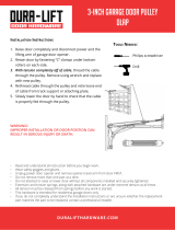
IMPORTANTINSTALLATIONINSTRUCTIONS
1. READAND FOLLOW ALL SAFETY, INSTALLATION 5.
AND OPERATION INSTRUCTIONS.( yo_J_ave
qvesto_so do o u_dosS;,_v_i_:s__st_;cto_ ca/ i/% 6.
_,, L/34 :S ., <_
2. Installonly on a properly balanced sectional garage door.
An improperly balanced door could cause severe injury.
Have a trained door system technician make repairs or
adjustments to cables, spring assemblies, andother 7.
hardware before installing the opener.
3. Removeall ropesand removeormake inoperativeall
locksconnectedtothegaragedoorbeforeinstallingopener. 8.
4. Wherepossible,installthe dooropener7feet or more
above thefloor. Forproductshavingan emergency
release,mounttheemergencyrelease6 feet abovethefloor.
Do NOT connect the opener to source of power
until instructed to do so.
Locate the Wall Control:
• Within sight of door,
• At minimum height of 5feet so small children are not
able to reach it, and
• Away from all moving parts of the door.
Installthe Entrapment WARNING Label next to the Wall
Control in a prominent location. Installthe Emergency
Release Tagon or next to the emergency release.
After installing the opener,the door must reverse within
2 seconds when it contacts a 1-1/2 inch high object (or a
2 x 4 board laid fiat) on the floor.
I
NOTE: Please follow ALL instructions in their NUMBERED sequence. Use wall control and safety sensors
provided with this unit. Do NOT substitute wall control or safety sensors.
NOTE: Throe J) p£/?ce _s:!_£ssse£ bSes am £}_ s 7
/:o0_ h){Fh sec_ions doo_,:
Clear a workspace area to unpack and organize box
and contents for assembly.
1. There are 4 boxes inside the carton. Each box is
numbered 1 - 4. Note that some openers will
contain the same parts and be packaged with
fewer boxes. Carefully remove the three
internal boxes (Labeled #1, 2, and 3) and place
them on the floor for easy access (Fig. 1-1).
These boxes contain assembly parts and the
contents are organized by assembly tasks. For
quick reference inside the lid of each box there is
a label illustrating the components inside.
2. Remove the motor power head and place it on
the floor for later use. Remove box #4 and
place it on the floor for later use.
Box Label Example
PN# 37026500123 05/15/2009 9

Rail Assembly for CHAIN DRIVE OPENER
NOTS: FoJ"sp£I ;ss£c/__mps, n s, ,s,nd bohfs
/oc,sS_ S_£ 0 Fro_r Box 1,
3. Remove the two rai sections that are not
connected to the chain and place them on
floor (Fig. 1-2, A).
4. Carefully remove the third rail section with
chain and plastic sleeve. Place rail section on
floor and extend chain straight out
(Fig. 1-2, B). Chain and rail should extend
approximately 7 feet.
5. Remove wire ties and plastic bag from chain.
Leave chain extended straight out on floor.
Avoid kinks in the chain by careful handling and
keeping chain flat on the floor.
6. Align the three rail sections by pulling the
chain straight and wrapping it around the
chain tensioner pulley (Fig. 1-3 & 1-4).
7. Attach the two rail clamps to the rail section
joints with (4) bolts and nuts. After both rail
clamps have been assembled to the rail sections,
securely tighten the bolts and nuts.
Rail Assembly for BELT DRIVE OPENER
NOTS: Eor sp£ mJl c/;_?mps, n s, _s,nd bo£s
ocs_ Sag 8 Ik_m Box f,
3. Remove the two rail sections that are not
connected to the belt and place them on floor
(Fig. 1-2, A).
4. Carefully remove the third rail section with
belt. Place rail section on floor, remove ties on
belt and extend belt straight out (Fig. 1-2, B).
Avoid twists and kinks in the belt by careful
handling and keeping belt flat on the floor. Belt
and rail should extend approximately 7 feet.
5. Align the three rail sections by pulling the belt
straight and wrapping it around the tensioner
pulley (Fig. 1-3 & 1-4).
6. Attach the two rail clamps to the rail section
joints with (4) bolts and nuts. After both rail
clamps have been assembled to the rail sections,
securely tighten the bolts and nuts.
CHAIN DRIVE RAILS
Chain Tensioner Pulley
BELT DRIVE RAILS
Tensioner Pulley I
CHAIN
Rail Clamps
Pail with chain
Power Head
Rail Clamp Bolts
Carriage Slide
Release
Knob Ra wth bet
PailCl_amp Nuts _G_ \ |
Center Rail @_/r_//
End Rail ___ _ @
ELT
B
Rail
r
Wrap around tensioner pulley
0 PN# 37026500123 05/15/2009

Assembly for CHAIN DRIVE OPENER
,._:._u,_..y. chsn ........o
of "<_L
HO'_£!: F@"powe£ he,_d end ss£ esse£ DJy/oceSe
t!:_g f £msy 8ox 1,
IVO_!: Copy se_/_,_ury bet _soFs'power heed
_qs,sye and _'eco_J £ on w#/,_uy"_,_n_yp,sWe,
1. Attach rail assembly to power head by aligning
the sprocket onto the motor shaft. Use (3)
bolts, 5/16 -18 x 1/2" (Fig. 1-5).
2. Tighten the chain by turning the adjustment
nut clockwise. The chain adjustment nut is
located in the Chain Pulley Bracket (opposite rail
end from the power head) (Fig. 1-6).
3. Tighten chain until chain is approximately 1/8
inch above the base of the rail at midpoint on
the rail (Fig. 1-6). Do NOT over tighten chain.
Set assembled power head and rail aside. Begin with
Section 2 INSTALLATION.
Assembly for BELT DRIVE OPENER
NOTE: FO;"powe_ °heed end m£ esse£ bF}//ocee
Bag f}osy B_ 1,
IVO_!: Copy seh,_d _,_umbes"f),_c,,f_'pow@ heed
hs_,rye _tnd _'ecosd Y' on _v,_,_;.y"sn(yp,_We
1. Attach rail assembly to power head by aligning
the sprocket onto the motor shaft. Use (3)
bolts, 5/16 -18 x 1/2" (Fig. 1-5).
2. Tighten the belt by turning the adjustment nut
clockwise. The belt adjustment nut is located in
the Belt Pulley Bracket (opposite rail end from the
power head) (Fig. 1-7).
3. Tighten belt until belt is approximately 1/8 inch
above the base of the rail at midpoint on the
rail (Fig. 1-7). Do NOT over tighten belt.
Set assembled power head and rail aside. Begin with
Section 2 INSTALLATION.
Bolts
Chain Pulley Bracket (atwall end of rail)
'Use 1/2" socket
on adjustment nut
i
Tighten nut to move pulley this direction
Chain
/ ?" /
"T-Rail
T-Rail at center of rail assembly
Belt Pulley Bracket (at wall end of rail)
_,_,__.- Use 1/2" socket
_.. I _ ,_..\_/EJ_ on adjustment nut
Tighten nut to move pulley this direction
)
Belt
/ /
T-Rail at center of rail assembly
Belt
Remove
Remove
"T-Rail

=
Finding header bracket mounting location.
, Close garage door.
-Use a pencil and level.
a) Mark center of garage door (one-half overall
width) on the wall with 6" vertical line at top
edge of door.
b) Continue this line on wall above door for
about 12" (Fig. 2-1, a).
, Raise garage door until top edge of door
reaches its maximum height (Fig. 2-2).
, With door at highest point.
- Measure height from top edge of door to floor
(Fig. 2-2).
, Close door again.
, Mark height measurement on wall above door
(Fig. 2-1, c).
- Make your mark across vertical line made earlier.
, Add 2-1/2" to height mark just made on wall. This
is location for header bracket (Fig. 2-1, d).
b) - extend
vertical line
c) - door at
highest point
top of door
in closed
position
d) - final
height mark
a) - 6" vertical
line
NT OFTRAVEL
SECTIONAL I Uli
FROM HERE SECTIONAL "
NOTE; Fk:__'he_?@?_bmckeit ,_;,ndbohfs Ioc,_;,e B_?ii;_2
2. Mounting the header bracket.
• Hold header bracket against wall (Fig. 2-3).
• Position bracket as shown.
- Place center on vertical line,
- Bottom edge on final height line.
• Mark screw hole locations on wall.
, Drill 3/16" pilot holes at each screw hole mark.
- Fasten header bracket with 2 lag screws
(provided) (Fig. 2-3).
2 PN# 37026500123 05/15/2009

1. Getting started.
, Position assembled rail on wall next to header
bracket (Fig. 2-4).
-Place material on floor under power head to
protect from scratching. (A box, stool, or
similar device may be needed to clear a
torsion spring.)
So;< 1=
2. Mounting the assembly.
, Attach rail to header bracket using clevis pin
and cotter pin (Fig. 2-5).
, Support power head on step-ladder to prevent
interference with header mounted (torsion)
spring.
NOTE: SeF0_,e BY:_ss schryen ito ce_ng_ ms_: _
ths sssery bJy _:_m pmd;_e_°sh:_i_nryen (F: _3 2.-4)
3 _bo_t Bo_' 1
, On finished ceilings, locate ceiling joists or
trusses using a stud finder or similar device.
Attach angle iron (not provided) to joists or
trusses through finish material using (provided)
lag screws (Fig. 2-6).
, On unfinished ceilings or open ceilings, straps
may attach directly to joists or trusses.
Depending on the garage construction, extra
framing material (not provided) which may be
required should be installed using appropriate
construction techniques (Fig. 2-6).
NOTE: Refi_£ o yeuy' oca bu £ cod_:;,sIbm
appmp_':&s_e consIr_ c ion Sx_ch_q ,_es,
, Attach mounting straps (not provided) to ceiling
using lag bolts (Fig. 2-6).
, Set height of power head to following
(Fig. 2-6).
a) Rail must clear door at door's highest point
of travel.
b) Rail must be level or at power head end
slightly below level.
, Securely tighten power head mounting bolts
and nuts.
, Carefully raise and lower door manually.
Ensure door does not contact any section of
power head or rail.
, Check that rail clamp bolts and nuts are tight.
, DO NOT PLUG OPENER IN YET!
COTTERPIN
(Chain drive
shown)
ANGLE IRON ON FINISHED CEILING
_ /DRYWALL
_J©_o oooo oo£01
Attach angle iron to beams
UNFINISHED OR OPEN BEAM
Extra framing
not needed
Mounting Straps
(not provided
bolts & nuts
bolts & nuts
Extra framing
NEEDED
ii_!i!!_ii!:iliii!iliii!!i!i!i!! i!i! i!:i!:!!!!;

I
uos oc,s, e 8_;'{11
ho_, b;os' 2
I,
,
Finding door bracket mounting location.
. Door bracket is mounted as high on door as
possible along vertical centerline and NO LOWER
THAN top set of rollers (Fig. 2-7).
Mounting the door bracket.
• Proper bracing should be verified at this point.
- Align door bracket centered on your vertical
centerline (Fig. 2-8).
- Attach using 3 self-drilling screws for sheet
metal or other light weight material.
- Use lag screws (not provided for solid
wooden sectional doors.
NO"IGE:_;; d]so_ am? noIs and boI% cMds ,snd
co_/_y pins _ocate Bag 5/7on, Box 2
1. Attach the arms.
, Fasten short branch of curved door arm to door
bracket using bolt and locking nut (Fig. 2-9).
, Fasten straight arm to carriage using clevis pin
and cotter pin (Fig. 2-9).
2. Connecting the arms.
, Slide carriage back and forth to adjust arm length.
-Position the straight arm 50 ° down from the
rail.
, With the arms arranged in this position, fasten
arms together using bolts and nuts spaced as
far apart as possible (Fig. 2-9).
i
short clevis pin & cotter pin
bolts as far
apart as
possible
4 PN# 37026500123 05/15/2009

1. Wall Control !ocation.
. Wall Control location should be in direct sight
of door.
. It should be at least five feet (5') above floor to
prevent small children from operating door.
. It must be away from any moving parts. (You
should NOT be able to reach the garage door
while standing at Wall Control.)
. Wall Control board screw connections are
polarized, (+) positive and (-) negative.
2a. Wiring (if pre-wired).
. Locate Wall Control pre-wired wire ends
(Fig. 3-1). (They should be located within the
guidelines mentioned above.)
. Split and strip ends of wire (Fig. 3-2).
. Fasten wire to Wall Control board screws on
back of Wall Control.
-Striped wire to the + (plus) terminal.
-White wire to the - (minus) terminal.
2b. Wiring (if NOT pre-wired).
. Pick a convenient location for mounting
Wall Control using the guidelines mentioned
above (Fig. 3-1).
. Run wire from power head to Wall Control
(Fig. 3-1).
. Split and strip ends of wire (Fig. 3-2).
. Fasten wire to Wall Control board screws on
back of Wall Control.
-Striped wire to the + (plus) terminal.
-White wire to the - (minus) terminal.
¢)
Separate
entry door
j_
Wire from
power head
...... to Wall Control
............::::.
Wall
Control
"Entrapment"
warning label
EXAMPLE ONLY!
IThis is an example of wire routing
__---I when NOT pre-wired. Your wire
- Jrouting may be different.

I
3. Securely fasten wires.
, Securely fasten wires to ceiling and
0q
wall using insulated staples provided.
-Use insulated staples.
-Staples should be snug only. Insulated
, if rear cover is attached to power head, Staple
remove it.
, On power head:
-Route Wall Control wires through wire guide
on power head.
- Split and strip ends of wire (Fig. 3-2 on
previous page).
- insert wire into terminal holes and lightly press in
the orange locking clips above each terminal
hole. (You can use a pencil or small screwdriver
to comfortably press in locking clips.) The white
wire into #1 terminal hole and striped wire into
the #2 terminal hole.
- Confirm wire lock by lightly tugging on the wire.
The wire should remain in the terminal hole.
. Do NOT install rear cover yet.
4. Mounting.
. Fasten Wall Control to wall with 2 screws
(provided) (Fig. 3-4).
, Remove protective backing from "Entrapment"
warning label (Fig. 3-5). The "Entrapment" label
is located in the center of this manual.
-Stick label on wall near Wall Control.
6 PN# 37026500123 05/15/2009

NO7£E': £oJ,"Sensop,_s sc_-_,vus,wh,s::÷__d iJ?suh:_ed
1. Mounting brackets.
. Mark both sides of garage door frame or wall no
higher than 6" and no lower than 5" above floor
(Fig. 4-1).
, Hold bracket against door frame or wall.
-Check if brackets extend out from wall far
enough, so tongue of bracket is beyond door,
tracks or any door hardware.
-If not:
a) Mounting bracket extensions are available
through an authorized Genie ®Dealer.
b) Blocks of wood, etc. may be substituted for
extensions.
, Center bracket on your mark (Fig. 4-2).
• Fasten each with 2 screws (Fig. 4-2).
NOTE; u_"g,qii_b'_u:_ke_,s_? be _cqmd o the
2. Mounting Safe-T-Beam ®Source (Red LED) and
Sensor (Green LEO).
" If garage has only one garage door.
- Determine which side of garage receives most
direct sunlight (Fig. 4-4).
-Red LED should always be on sunny side
whenever possible (Fig. 4-4).
. For multiple doors.
-Preventing crossed signals is critical.
-Place source and sensor modules on adjacent
doors facing in opposite directions (Fig. 4-4).
. Slide source/sensor onto tongue of bracket until
it clicks into place (Fig. 4-3).
3a. Wiring (If NOT pre-wired).
, Route wire from Safe-T-Beam ®sensors to power
head using method shown in (Fig. 4-5a).
, Securely fasten wires to wall and ceiling _p
as you go (Fig. 4-6 on next page).
-Use insulated staples.
-Staples should be snug only.
Insulated
Staple
Source
Power
Head
=
Sensor
'1'1 I'1'
I I I I
| | ! !
!65 43 211or!6s 4S 21!
Dashed Line = striped wire
Solid Line = white wire
I

I
3b.
e
e
e
Wiring (pre-wired).
Route wire from wall to Safe-T-Beam ®sensors
(Fig. 4-5b).
Splice pre-wiring to shortened sensor wire,
match wire pairs dash-to-dash (striped-to-
striped) and plain-to-plain (white-to-white).
- Trim sensor wire to approximately one foot
(1 ft) from sensor.
- Split and strip ends of sensor wires and
pre-wired wires (Fig. 4-7).
- Splice wires together with (provided)
wire nuts.
Route wire from ceiling to power head Wire Nut
(Fig. 4-5b).
Securely fasten wires where they exit
wall and ceiling as you go.
-Use insulated staples.
-Staples should be snug only.
Insulated
Staple
4. Split and strip ends of sensor wires (Fig. 4-7).
NOTE: Bo_ ',e_:_coy@" oc_ ;e Box 4
5. Attach Safe-T-Beam ®wire to power head wire
terminal.
, Route Safe-T-Beam ®wires through wire guide
on power head.
-Insert wire into terminal holes and lightly press
in the orange locking clips above each terminal
hole. (You can use a pencil or small
screwdriver to comfortably reach in and lightly
press down locking clips.) Insert white wires to
'even' numbered terminal holes and striped
wires into 'odd' terminal holes (Fig. 4-8).
Locking Terminal
- Confirm wire lock by lightly tugging on the wire.
The wire should remain in the terminal hole.
• Do not install the white (lamp) cover at this time.
r
L.
I I Source
L
\
Ceiling ]
Power (
Head
'1 '1
I I
i65 4S 21Jor165 43 211
Dashed Line = striped wire
Solid Line = white wire
Insert Wire
Wire Into Connector .. .... "°"
', _ Wire
pre-wired
Sensor
S..... _,,.._.,_.. h._i1_,r.o,(ec,t/on g/_,reaea m
wire guide
8 PN# 37026500123 05/15/2009

Motor Cover Screws
Plug the opener into a properly grounded
electrical outlet (Fig. 5-1).
instructions for Electrician.
, Remove power from circuit.
, Remove rear cover and motor cover.
- Remove four motor cover screws (Fig. 5-2).
, Remove existing power cord and strain relief
from the 7/8" dia. hole and discard (Fig. 5-3).
, Connect permanent wiring to power head using
7/8" diameter hole.
-White to white/black to blacldground to green.
- Use only UL recognized wire nuts.
. Wires inside the power head must be at least 6"
in length.
. Replace motor cover and rear cover and
re-energize the circuit.
P_70T_!!:The GG,,nJ_Co_'_p_ny _; no ons_!::_:_;;,f_:._
;J:; en@n_ dec n
Check Safe-T-Beam ®alignment (Fig. 5-4).
, insure that no part of door or its hardware is
in path between lenses of source and sensor.
, insure that tops of lenses are between 5" - 6"
above the floor (Fig. 5-4). The brackets are
flexible, and can be adjusted slightly if needed.
, Adjust the Red LED transmitter by aiming the
unit directly at the Green LED receiver. Use the
adjustment screw located on the top of the
transmitter housing to make adjustments.
, The Red LED transmitter will blink if there is a
misalignment. When the LED units are aligned
the Red LED will remain ON continuously.
, After the alignment is finished tighten the
adjustment screws on both sensors.
, Do NOT use an extension cord.
, Do NOT use a portable generator. This product
is designed to operate using standard
household current.
, Do NOT use alternatepowe_supplies.
1. When the garage door is opening, its movement
will not be influenced if the Safe-T-Beam ®is
obstructed.
.
3.
.
if the Safe-T-Beam ®is obstructed before the
garage door fully closes, the door will not close.
When the garage door is closing, if Safe-T-Beam ®
is cut off by people or obstacle, the garage door
will reverse automatically to its fully opened position.
(Meanwhile, the opener light will keep blinking until
door moves to its fully opened position.)
if the Safe-T-Beam ®System fails, loses power,
or is installed improperly, press and hold the
Wall Control "open/close" button until the door
reaches its fully closed position. The LED
indicator light on the power head will be green
and blink twice (Pattern: C,C, pause C,C, pause)
to inform you to eliminate the problem first.
if you release the "open/close" button on the
Wall Control during the closing movement the
door will reverse automatically to its fully
opened position.
iihiiiiiiii!iiii!iiii!ii;iiiiiii;i!iii!ii11ii1i111!1!i!!!i!ii!ii ;iiiii;
i

I
20
The OPEN (UP) and CLOSE (DOWN) door positions
are controlled by making the adjustments on the
panel located on the bottom of the power head. The
adjustments that can be made are:
• Close Travel Limit,
• Open Travel Limit,
Adjust Closing Force
Adjust Opening Force
Transmitter Programming
ENGAGE CHAIN/BELT CONNECTOR
CARRIAGE
1. Press and hold the "Close Travel Limit" B button
until the chain or belt connector advances and
engages to the Carriage Assembly (Fig. 6-2).
B) CLOSE TRAVEL LIMIT
1. Press and hold the "Close Travel Limit" D button
until the door is fully closed.
2. You can quickly press and release the "Close
Travel Limit"[] button to move the door in small
increments. You can also use the "Open Travel
Limit" [] button to move the door slightly in the
UP direction.
3. Door is fully closed when the bottom edge of door
presses firmly onto the ground.
4. Once the door is in the desired position, press and
release the "Close SET Limit" [] button. The
LED indicator light will blink green once. This
stores the closed position in memory.
C) OPEN TRAVEL LIMIT
1. Press and hold the "Open Travel Limit" [] button
to move the door to its fully opened position. This
starts the opener moving in the UP direction.
2. Hold the "Open Travel Limit" [] button until the
door is in the fully opened position that you desire,
then release this button.
3. You can quickly press and release the "Open
Travel Limit" _ button to move the door in small
increments. You can also use the "Close Travel
Limit" [] button to move the door slightly in the
DOWN direction.
4. Once the door is in the desired position, press
and release the "Open SET Limit" [] button.
The LED indicator light will blink green twice.
This stores the opened position in memory.
PN# 37026500123
LED
Indicator Light
Open
Open Set Limit Up Force
\ _;,.(_,',}..... Travel Limit Button, OPEN C°stt_Clen t
LEARN MANUAL LIMIT FORCE
\
Code CODE Close CLOSE Down Force
Button Close
Travel Limit Set Limit Control
Button Adjustment
/_1ove.
Latch
Movement
Carriage Assembly
Carriage Assembly
05/15/2009
/