Littfinski DatenTechnik 050702 User manual

Type
User manual

Littfinski DatenTechnik 050702 is a light interface that connects your computer to your model railway lighting system, allowing you to control up to 280 outputs individually. It supports various lighting effects, including neon lights, gas street lamps, flashing blue lights, light chains, and traffic lights. You can connect up to 7 Light-Display or Light-Power modules to the interface, which provides a total of 40 outputs with 0.5 Ampere each or 24 outputs with 2.5 Ampere each.

Littfinski DatenTechnik 050702 is a light interface that connects your computer to your model railway lighting system, allowing you to control up to 280 outputs individually. It supports various lighting effects, including neon lights, gas street lamps, flashing blue lights, light chains, and traffic lights. You can connect up to 7 Light-Display or Light-Power modules to the interface, which provides a total of 40 outputs with 0.5 Ampere each or 24 outputs with 2.5 Ampere each.

L
ittfinski
D
aten
T
echnik (
LDT
)
Operating Instruction
Light-Interface
for the
PC-Light Control
Light@Night
LI-LAN-F
Part No.:
050702
>> finished module <<
The Light-Interface for the network interface (LAN) of a
computer combines together with a minimum of one
Light-Display-Module or Light-Power-Module the
hardware for the PC-Light Control Light@Night.
It is possible to connect up to 7 Light-Display- and/or Light-
Power-Modules onto each Light-Interface LI-LAN.
The lighting effects (neon lamps, gas street lamps, flashing
blue light, light chains, traffic lights and others) can be assigned
individual to a maximum of 280 outputs.
Suitable for analog and digital model railways.
This product is not a toy! Not suitable for children under 14 years of age! The kit
contains small parts, which should be kept away from children under 3! Improper
use will imply danger of injuring due to sharp edges and tips! Please store this
instruction carefully.
Introduction/Safety instruction:
You have purchased a kit or a finished module of the Light-
Interface LI-LAN for the PC-Light control Light@Night for your
analog or digital model railway.
The Light-Interface LI-LAN is a high quality product that is
supplied within the assortment of Littfinski DatenTechnik (LDT).
We are wishing you having a good time using this product.
The finished module comes with 24 month warranty.
Please read the following instructions carefully. Warranty will
expire due to damages caused by disregarding the operating
instructions. LDT will also not be liable for any consequential
damages caused by improper use or installation.
Also, note that electronic semiconductors are very sensitive to
electrostatic discharges and can be destroyed by them.
Therefore, discharge yourself before touching the modules on
a grounded metal surface (e.g. heater, water pipe or protective
earth connection) or work on a grounded electrostatic
protection mat or with a wrist strap for electrostatic protection.
We designed our devices for indoor use only.
Connect the Light-Interface to the PC and
the Light-Display-Module:
Attention: Before starting any installation switch off the
drive voltage by pushing the stop button and/or
disconnect the main supply and switch-off the computer.
The Light-Display-Modules contain a large capacitor
which has to be completely discharged before the Light-
Display-Module can be connected or disconnected.
Please wait a couple of minutes after switching off the
supply transformer before you connect or disconnect the
Light-Display-Module.
The Light-Interface LI-LAN for the Network-Interface (LAN) of a
computer will be supplied together with a Standard-Patch
cable of 2 meter length. With this cable can be the Light-Interface
LI-LAN directly connected to a Hub, Switch or Router.
For a direct connection between PC and LI-LAN you will need
a Cross-Over-Network-Cable. This cable will be available at
any computer shop. If you use a PC with Gigabit-Connection
you can as well use the supplied Standard-Patch cable for a
direct connection.
Connect now the Light-Interface via the 10-poles socket bar
BU1 either to a Light-Display- or a Light-Power-Module. Take
special care that the pin bars of the Light-Display- or the
Light-Power-Module are not offset connected into the socket
bar of the Light-Interface.
Attend as well to the Operation Manual of the Light-Display-
and the Light-Power-Module.
Leuchtdiode
light-emitting diode
Vorwiderstand
series resistor
Modellbahn-
lämpchen
model incandescent
lamp
braun
brown
gelb
yellow
Vom Modellbahntrafo
From transformer
Trxcom
Littfinski DatenTechnik (LDT)
DMX
KL5
BU2
PC/
LAN
Light-LAN (Ethernet Interface)
Rev. 1.0
Taster
BU1
ST1
KL1 KL2 KL3 KL4
+5V
GND
1
2
3
4
5
6
7
8
IC8
C4
C1
C2 L1
C3
Q1
CR1
C20
C19
C18
C17 C14
C12
C13C16
C15
RN1 RN2
IC3
IC1
IC2
C10
C21
C11
IC6
IC5
IC7
D1
C6
C5
C8
C9
white
weiss
white
weiss
KL4 KL3 KL2 KL1
KL7
BU1 ST1
4
5
6
7
8
26
27
28
29
30
31
32
25
9
10
11
12
13
14
15
16
18
19
20
21
22
23
24
17
1
2
3
GBS-Display / Light-Display
Rev. 1.8
Littfinski DatenTechnik (LDT)
KL5
braun
gelb
10...18V~
12...24V=
KL6 BU2
39
38
37
36
35
34
33
40
BU3
OUT
IN
It is possible to connect up to 7 Light-Display- and/or Light-
Power-Modules to one Light-Interface. For this assembly shall
be the second Display-Module connected to the first Display-
Module via the 10-poles pin bar either directly or with the
extension cable “Kabel Light@Night xm”.
The Light Interface receives always the operating voltage from
the first Light-Display- respectively Light-Power-Module. The
Light-Interface contains a galvanic separation to the interface
of the PC. Therefore is no direct electrical connection between
model railway and computer existent.
One Light-Display-Module offers 40 light control outputs with
0.5 Ampere each. One Light-Power-Module offers 24 outputs
of 2.5 Ampere each. Each output can be individual configured via
the Light@Night PC-Software.
Further details referring to the wiring of lamps and light
emitting diodes are available within the Operating Instruction of
the Light-Display- respectively Light-Power-Module.
Colored sample connections for the wiring can be additionally
found on our web site www.ldt-infocenter.com at the section
Sample Connections
.
Installation of Light@Night demonstration
software:
The Light@Night PC-Software runs on almost any PC with a
Windows operating system of Windows 95 or higher. We
recommend particularly modern operating systems.
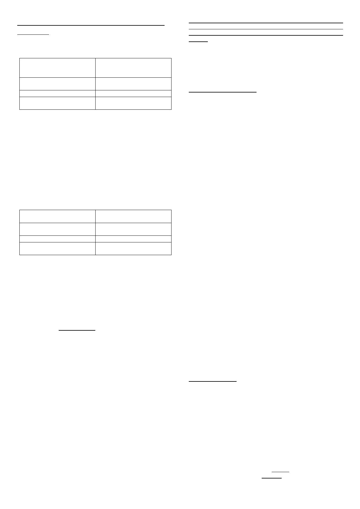
Operating system Windows 95, 98, Me, NT,
2000, XP, Vista, Win 7, 8 or
10
CPU Intel or AMD from 300MHz
clock frequency
Working memory 64Mbyte RAM
Interface to the Light-
Interface
Network connection (LAN)
If you want to run the Light@Night PC-Software together with
a model railway control software (e.g. Railware, Win-Digipet,
TrainController or iTrain) on your PC you have to attend to
some strict specific requirements, because the control
software as well as Light@Night PC-software need some
system resources.
In this case please find out the system requirements of your
model railway control software and attend to the specific
instruction.
In a doubtful case it could be considerable to use a second PC
exclusive for Light@Night.
In case of a common operation of Light@Night PC-software
and a model railway control software the following PC-system
requirements are necessary:
Operating system Windows 2000, XP, Vista,
Win 7, 8 or 10
CPU Intel or AMD from 800MHz
clock frequency
Working memory 256Mbyte RAM
Interface to the Light-
Interface
Network connection (LAN)
Together with the Light-Interface LI-LAN you received a CD-
ROM containing the Light@Night PC-demonstration
software.
This demo-software enables you to test the Light@Night
hardware for the Layout Light Control without the complete
version. There is a substantial difference to the complete
software version. The light outputs of the demo-version offers
only light effects for incandescent lamps and flashing lights.
The DMX-Interface for the Surrounding Light Control and the
inputs of up to eight push buttons for the external control of
light effects are not supported.
The complete version of the Light@Night PC-software for all
light effects (neon lights, gas street lamps, flashing blue lights,
light chains, traffic lights and many others) the support of the
DMX-Interface and the external push-buttons including a manual
(in German language only) is available by company Railware
(https://railware.de).
For the installation of the demo-software please insert the
supplied CD-ROM into the CD-ROM drive of your computer:
The installation program will start automatically. In case the
function “auto start” has been set to “off” on your PC please
start the program with Execute… at the Windows start
menu and enter the following line (without ` sign):
´d:\lightatnightdemo.exe´. Please replace the letter `d`
with the letter-code of your CD-ROM drive.
Follow now the instructions of the installation program.
Enter the directory where Light@Night shall be installed.
Recommendation: ´C:\Program\LightATNight´.
The following installation will run automatically.
Finally please restart your PC.
Before the LAN configuration please connect an incandescent
lamp or a light emitting diode with serial resistor to the
output 1 of the Light-Display respectively to the Light-Power-
Module which is the first module connected directly to the Light-
Interface LI-LAN.
Further information for the wiring of incandescent lamps
and light emitting diodes can be found within the operating
instruction of the Light-Display- respectively Light-Power-
Module.
Now switch-on the power supply (transformer or of the
switched mode mains power supply) for the first Light-Display-
respectively Light-Power-Module.
Control at first the network connection. The green LED of the LI-
LAN network socket has to lighten constantly, the yellow LED
will flicker during general network operation.
LAN-Configuration:
To integrate the Light-Interface LI-LAN into your PC-Network
you have to start the program IP Programmer“. You will find
this program at the Windows start directory under “Programs
and “Light@Night“.
Click now onto “Search and Readat the IP Programmer. If the
IP Address of 192.168.1.76 (pre-setting of the Light-Interface
LI-LAN) is suitable for your network you will receive immediately
an information about the settings.
If you need a correction of the IP-Address you can do this at
the lower part of the window. For your orientation you can read
the IP-Address of your computer left top side.
As long as the input of the IP-Address is incomplete the
background of the input area will be yellow. If the selected IP-
Address will be used already by another member the
background will be red. If the IP-Address will be suitable for
your network the background will be green.
Now activate the button Programming”. The Light-Interface
LI-LAN confirms the receipt of the new IP Address by indicating
with short flashing at the output of the first Light-Displays.
Close now the IP Programmer and start the Light@Night Demo
software which can be found as well inside the Windows Start
Directory under “Program” and Light@Night.
Within the Demo software and the menu Option open the
dialog Interface”. Select the Hardware type Light-LAN
Interfaceand register under interface the previous configured
IP Address. Or use the predefined IP Address 192.168.1.76, in
case you have not programmed a new IP-Address at the IP-
Programmer.
Close now the dialog with OK”. The selected IP-Address will
now be indicated at left side bottom on the status line. If the
Light@Night Demo software has now a connection to the
Light-Interface LI-LAN the LED on the status line left next to
the IP-Address will lighten in green color.
For introduction to the various features of the Light@Night PC-
Software the software contains within the help function detailed
help-descriptions. Just press the key F1and read the section
Operating the Software” and “Configuration”.
The Complete Version of the PC-Software will be supplied
together with a manual which described all light effects of the
PC-Light Control Light@Night in detail. At the section
Downloadson our Web-Site you can as well download this
manual.
Accessories:
For the assembly of the Light@Night hardware we offer
suitable assembly material under the order coder “MON-SET”.
A set consist of 4 plastic distance washer and 4 matching
wood screws.
Under the order code Kabel Light@Night xmyou can order
an extension cable for the Light-Display- and Light-Power-
Module for a possible assembly of the modules at a 0.5m, 1m or
2 meter distance.
Made in Europe by
Littfinski DatenTechnik (LDT)
Bühler electronic GmbH
Ulmenstraße 43
15370 Fredersdorf / Germany
Phone: +49 (0) 33439 / 867-0
Internet: www.ldt-infocenter.com
Subject to technical changes and errors. 09/2022 by LDT
  • Page 1 1
  • Page 2 2

Littfinski DatenTechnik 050702 User manual

Type
User manual

Littfinski DatenTechnik 050702 is a light interface that connects your computer to your model railway lighting system, allowing you to control up to 280 outputs individually. It supports various lighting effects, including neon lights, gas street lamps, flashing blue lights, light chains, and traffic lights. You can connect up to 7 Light-Display or Light-Power modules to the interface, which provides a total of 40 outputs with 0.5 Ampere each or 24 outputs with 2.5 Ampere each.

Ask a question and I''ll find the answer in the document

Finding information in a document is now easier with AI